
LED-Aggregat
Sicherheitshinweise
Einbau und Montage elektrischer Geräte dürfen
nur durch Elektrofachkräfte erfolgen. Dabei sind
die geltenden Unfallverhütungsvorschriften zu
beachten.
Bei Nichtbeachten der Anleitung können Schä-
den am Gerät, Brand oder andere Gefahren ent-
stehen.
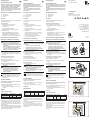
Geräteaufbau (Bild 1)
(1) Kontaktbrücke
(2) Steckkontakte
(3) N-Klemme
Funktion
Das LED-Aggregat dient der Beleuchtung von
Schaltern und Tastern.
Bestimmungsgemäßer Gebrauch
Das LED-Aggregat ist einzusetzen in
- Wippschalter Aus/Wechsel, Kreuz, 2-polig Aus
10 AX
- Wippenschalter Serien
- Wipptaster und Wippentaster
Nicht verwendbar für
- Wippentaster Best.-Nr. 5038 08 und Gruppen-
Wippentaster Best.-Nr. 5034 04
- Tastschalter und Zugschalter sowie Wippschalter
und -taster der Jahre 1985 bis 1995
Informationen für Elektrofachkräfte
Montage und elektrischer Anschluss
GEFAHR !
Elektrischer Schlag bei Berühren
spannungsführender Teile.
Elektrischer Schlag kann zum Tode führen.
Vor Arbeiten an Gerät oder Last alle
zugehörigen Leitungsschutzschalter
freischalten. Spannungsführende Teile in
der Umgebung abdecken!
LED-Aggregat montieren (Bild 2)
<LED-Aggregat mit Steckkontakten von vorne in
die Kontaktbuchsen führen und hineindrücken bis
es einrastet.
Verdrahtung Ausschaltung beleuchtet
Das LED-Aggregat leuchtet bei „AUS“
Die Kontaktbrücke ist montiert.
<Schalter nach Verdrahtungsplan anschließen
(Bild 3)
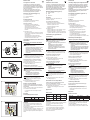
Verdrahtung Ausschaltung Kontroll
Das LED-Aggregat leuchtet bei „EIN“
ACHTUNG!
Kurzschluss durch Anschluss des N-Leiters
bei montierter Kontaktbrücke.
LED-Aggregat wird zerstört.
Kontaktbrücke vor Anschluss des N-Leiters
entfernen.
<Die Kontaktbrücke entfernen (Bild 1, 1).
HinterderKontaktbrückebendetsichdie
Schraubklemme zum Anschluss des N-Leiters
(Bild 1, 3).
<Schalter nach Verdrahtungsplan anschließen
(Bild 4).
Hilfe im Problemfall
Kurzschluss bei Einschalten der Netzspannung
bei Ausschaltung Kontroll
Ursache: Kontaktbrücke wurde nicht entfernt bevor
der N-Leiter angeschlossen wurde.
LED-Aggregat ist beschädigt und muss ausge-
tauscht werden.
Anhang
Technische Daten
LED-Aggregat 1686 1686 01 1687
Betriebs-
spannung
230 V~ 230 V~ 12 … 48 V~
Nennstrom 1 mA 0,4 mA 0,2 … 0,9 mA
Gewährleistung
Technische und formale Änderungen am Produkt,
soweit sie dem technischen Fortschritt dienen, be-
halten wir uns vor.
Wir leisten Gewähr im Rahmen der gesetzlichen
Bestimmungen.
Im Gewährleistungsfall bitte an die Verkaufsstelle
wenden.
LED unit
Safety instructions
Electrical equipment must only be installed
andassembledbyqualiedelectricians.
Always follow the relevant accident prevention
regulations.
Failure to comply with these instructions
mayresultindamagetothedevice,reor
other hazards.
Structure of the device (Figure 1)
(1) Contact bridge
(2) Plug-in contacts
(3) N-terminal
Function
The LED unit is used for lighting switches and
push-buttons.
Correct use
The LED unit must be used in
- rocker switches change-over, intermediate,
2poleon/o10AX
- Rockers switch series
- Rocker push-button and rockers push-button
Not useable for
- Rockers push-button order no. 5038 08 and
group rockers push-button order no. 5034 04
- Push-button and pullcord switches,
rocker switches and rocker push-buttons
from the years 1985 to 1995.
Information for electricians
Assembly and electrical connection
DANGER!
Touching live parts can result in an electric
shock.
An electric shock can lead to death.
Before working on the device or load,
disconnect all associated circuit breakers.
Cover all live parts in the area!
Installing LED unit (Figure 2)
<Insert LED unit with plug-in contacts from the
front into the contact sockets and press until it
clicks into place.
Wiringcut-olightsup
The LED unit lights up when „OFF“.
The contact bridge is installed.
<Connect switch acc. to wiring diagram (Figure 3).
Wiringcut-ocontrol
The LED unit lights up when „ON“
ATTENTION!
Short circuit by connection of the neutral
conductor on installed contact bridge.
LED unit will be destroyed.
Remove contact bridge before connecting
the neutral conductor
<Removing the contact bridge (Figure 1, 1).
Behind the contact bridge is the screw terminal
for connecting the neutral conductor (Figure 1, 3).
<Connect switch acc. to wiring diagram (Figure 4).
Troubleshooting
Short-circuit when switching on the power
supplyoncut-ocontrol
Cause: Contact bridge was not removed before con-
necting the neutral conductor.
LED unit is damaged and must be replaced.
Appendix
Specications
LED unit 1686 1686 01 1687
Operating
voltage
230 V~ 230 V~ 12 … 48 V~
Rated current 1 mA 0.4 mA 0.2 … 0.9 mA
Warranty
We reserve the right to make technical and formal
changes to the product in the interest of technical
progress.
Our products are under guarantee within the scope
of the statutory provisions.
If you have a warranty claim, please contact the
point of sale or ship the device postage free with a
description of the fault to the appropriate regional
representative.
LED-Aggregat
LED unit
Best.-Nr. 1686, 1686 01, 1687
Order no. 1686, 1686 01, 1687
Montageanleitung
Installation instructions
Berker GmbH & Co. KG
Zum Gunterstal
66440 Blieskastel/Germany
Tel.: + 49 6842 945 0
Fax: + 49 6842 945 4625
E-Mail: info@berker.de
www.berker.com
02/2021
6LE007682A
2
1
(1)
(3)
(2)
NL
LED-aggregaat
Veiligheidsinstructies
Elektrische apparaten mogen uitsluitend worden
ingebouwd en gemonteerd door elektromonteu-
rs. Daarbij moeten de geldende ongevallenpre-
ventievoorschriften worden aangehouden.
Wanneer deze handleiding niet in acht wordt ge-
nomen, kunnen schade aan het apparaat, brand
of andere gevaren optreden.
Opbouw van het apparaat (afbeelding 1)
(1) Contactbrug
(2) Steekcontacten
(3) N-klem
Functie
De LED-aggregaat is bedoeld voor de verlichting van
schakelaars en toetsen.
Bedoeld gebruik
De LED-aggregaat wordt toegepast in
- Wipschakelaar uit/wissel, kruis,
2-polig uit 10 AX
- Wippenschakelaar standaard
- Wipimpulsdrukker en wippenimpulsdrukker
Niet toepasbaar voor
- Wippenimpulsdrukker bestelnr. 5038 08 en
groepentuimelschakelaar bestelnr. 5034 04
- Tastschakelaar en trekschakelaar plus wip-
schakelaar en -knop uit de jaren 1985 t/m 1995
Informatie voor elektromonteurs
Montage en elektrische aansluiting
GEVAAR !
Gevaar voor elektrische schokken bij
aanraking van spanningsvoerende delen.
Elektrische schokken kunnen dodelijk letsel
veroorzaken.
Voor de werkzaamheden aan het apparaat
of de last alle bijbehorende installatie-
automaten vrijschakelen. Onderdelen onder
spanning in de omgeving afdekken!
LED-aggregaat monteren (afb. 2)
<LED-aggragaat met steekcontacten van voren
in de contactbussen plaatsen en vastdrukken tot
deze klikt.
Bedrading uitschakeling verlicht
Het LED-aggregaat brandt bij „UIT“
De contactbrug is gemonteerd.
<Schakelaar aansluiten conform het aansluit-
schema (afb. 3)
Bedrading uitschakeling bediening
Het LED-aggregaat brandt bij „AAN“
OPGELET!
Kortsluiting door aansluiting van de
N-leider bij gemonteerde contactbrug.
LED-aggregaat wordt beschadigd.
Contactbrug voor aansluiting van de
N-leider verwijderen.
<De contactbrug verwijderen (afb. 1, 1).
Achter de contactbrug bevindt zich de schroef-
klem voor aansluiting van de N-leider (afb. 1, 3).
<Schakelaar aansluiten conform het aansluit-
schema (afb. 4)
Hulp bij problemen
Kortsluiting bij inschakelen van de netspanning
bij uitschakeling bediening.
Oorzaak: de contactbrug is niet verwijderd voordat
de N-leider werd aangesloten.
LED-aggregaat is beschadigd en moet worden
vervangen.
Bijlage
Technische gegevens
LED-aggregaat 1686 1686 01 1687
Bedrijfs spanning 230 V~ 230 V~ 12 … 48 V~
Nominale stroom 1 mA 0,4 mA 0,2 … 0,9 mA
Garantie
Wij behouden ons het recht voor om technische en
formele wijzigingen aan het product aan te brengen,
voor zover deze de technische vooruitgang dienen.
Onzegarantievoldoetaandedesbetreendewette-
lijke bepalingen.
Neem bij garantiekwesties contact op met het verko-
oppunt of stuur het apparaat franco met beschrijving
vandeopgetredendefectennaardedesbetreende
regionale vertegenwoordiging.
NL
3
L
3036
11
mm
L
N
4
L
3036
11
mm
L
N
PL

Module LED
Consignes de sécurité
L‘intégration et le montage des appareils
électriques doivent uniquement être réalisés
par un électricien spécialisé. Les prescriptions
de prévention des accidents en vigueur doivent
alors être respectées.
En cas de non-respect de la notice, des
dommages sur l‘appareil, des incendies ou
d‘autres dangers peuvent se produire.
Structuredel‘appareil(gure1)
(1) Pont de contact
(2) Contactsenchables
(3) N-Borne
Fonctionnement
Le module LED est destiné à l‘éclairage
d‘interrupteurs et de poussoirs.
Utilisation conforme
Le module LED peut être installé dans
- des interrupteurs à bascule 2 directions,
des inverseurs, bipolaire 10 A,
- des interrupteurs à bascules séries,
- des poussoirs à bascule et des poussoirs à
bascules.
Ne convient pas pour
- des poussoirs à bascules de référence 5038 08
et des groupes de poussoirs à bascules de réfé-
rence 5034 04,
- des interrupteurs à poussoir et à tirette,
des interrupteurs à bascule et des poussoirs
à bascule des années 1985 à 1995.
Informations destinées aux électriciens
spécialisés
Montage et raccordement électrique
DANGER !
Choc électrique en cas de contact avec
les pièces sous tension.
Un choc électrique peut entraîner la mort.
Déconnecter tous les disjoncteurs de
protection de circuit correspondants avant
les travaux sur l‘appareil ou la charge.
Couvrir les pièces sous tension situées
à proximité !
MontagedumoduleLED(g.2)
<Introduire le module LED avec les contacts en-
chablesparl‘avantdanslesdouillesdecontact
etl‘encherjusqu‘àcequ‘ils‘encliquète.
Câblage Éclairage en cas de désactivation
Le module LED s‘allume en position « ARRÊT ».
Le pont de contact est monté.
<Raccorder l‘interrupteur conformément au
schémadecâblage(g.3)
Câblage Contrôle de désactivation
Le module LED s‘allume en position « MARCHE ».
ATTENTION !
Court-circuit dû au raccordement du
conducteur N lorsque le pont de contact
est monté.
Le module LED est endommagé.
Retirer le pont de contact avant le
raccordement du conducteur N.
<Retirerlepontdecontact(g.1,1).
La borne à vis pour le raccordement du
conducteurNsetrouvederrièrelepontde
contact(g.1,3).
<Raccorder l‘interrupteur conformément
auschémadecâblage(g.4).
Aide en cas de problème
Court-circuit lors de l‘activation de la tension
secteur en cas de branchement de contrôle de
désactivation
Cause : le pont de contact n‘a pas été retiré avant
le raccordement du conducteur N.
Le module LED est endommagé et doit être
remplacé.
Annexes
Caractéristiques techniques
Module LED 1686 1686 01 1687
Tension de service 230 V~ 230 V~ 12 … 48 V~
Courant nominal 1 mA 0,4 mA 0,2 … 0,9 mA
Garantie
Sousréservedemodicationstechniquesetde
forme, dans la mesure où elles sont utiles au pro-
grèstechniques.
Nos appareils sont garantis dans le cadre des dispo-
sitions légales en vigueur.
Pour toute demande en garantie, s’adresser à votre
revendeur ou retourner l’appareil en port payé au
représentant régional et joindre une description du
défaut.
Gruppo LED
Indicazioni di sicurezza
L‘incasso e il montaggio degli apparecchi elet-
trici devono essere eseguiti solo da elettricisti
specializzati. Allo scopo devono essere osser-
vate le norme antinfortunistiche vigenti.
Il mancato rispetto delle istruzioni può provocare
danni all‘apparecchio, incendi o altri pericoli.
Strutturaapparecchio(gura1)
(1) Ponte di contatto
(2) Spine
(3) Morsetto N
Funzione
Il gruppo LED serve per l‘illuminazione di
interruttori e pulsanti.
Uso conforme alle indicazioni
Il gruppo LED deve essere inserito in
- interruttore a bilanciere interruttore/deviatore,
invertitore,bipolareO10AX
- interruttori a bilanciere in serie
- pulsante a bilanciere
Non utilizzare per
- pulsante a bilanciere n. ordine 5038 08 e gruppi
pulsante a bilanciere n. ordine 5034 04
- interruttori a pulsante e a tirante e per interruttori
e pulsanti a bilanciere degli anni dal 1985 al 1995
Informazioni per gli elettricisti
specializzati.
Montaggio e collegamento elettrico
PERICOLO!
Scosse elettriche in caso di contatto con
componenti sotto tensione.
Le scosse elettriche possono provocare la
morte.
Disattivare tutti i relativi interruttori
magnetotermici prima di eseguire
operazioni sull‘apparecchio o sul carico.
Coprire tutti i componenti sotto tensione
presenti nella zona!
MontaggiodelgruppoLED(gura2)
<Condurre il gruppo LED con spine dal davanti
nellepreseespingeredentronchénonscatta.
Disattivazione cablaggio illuminata
Il gruppo LED si illumina con „OFF“
Ilpontedicontattoèmontato.
<Collegamento dell‘interruttore in base allo
schemadicablaggio(gura3)
Controllo disattivazione cablaggio
Il gruppo LED si illumina con „ON“
ATTENZIONE!
Cortocircuito con collegamento del
conduttore N con ponte di contatto
montato.
Il gruppo LED viene danneggiato
irreparabilmente.
Rimuovere il ponte di contatto prima del
collegamento del conduttore N.
<Rimuovereilpontedicontatto(gura1,1).
Dietro il ponte di contatto si trova il morsetto
a vite per il collegamento del conduttore N
(gura1,3).
<Collegare l‘interruttore in base allo schema
dicablaggio(gura4).
Assistenza in caso di problemi
Cortocircuito con accensione della tensione
di rete con disattivazione controllo
Causa:ilpontedicontattononèstatorimossoprima
del collegamento del conduttore N.
IlgruppoLEDèdanneggiatoedeveessere
sostituito.
Appendice
Dati tecnici
Gruppo LED 1686 1686 01 1687
Tensione
d'esercizio
230 V~ 230 V~ 12 … 48 V~
Corrente
nominale
1 mA 0,4 mA 0,2 … 0,9 mA
Garanzia
Ciriserviamoildirittodiapportaremodichetecniche
e formali al prodotto purché utili al progresso
tecnologico.
Oriamogaranziadelledisposizionidilegge.
In caso di necessità siete pregati di rivolgervi al
punto vendita oppure di spedire l‘apparecchio in
porto franco, con descrizione dell‘anomalia,
al centro di assistenza.
Dioda LED
Instrukcjedotyczącebezpieczeństwa
Urządzenieelektrycznedoinstalacjiimontażu
wyłącznieprzezwykwalikowanegoelektryka.
Należyzawszepostępowaćzgodniezodpowied-
nimiprzepisamidotyczącymizapobieganiu
wypadkom.
Nieprzestrzeganietychinstrukcjimożespowodo-
waćuszkodzenieurządzenia,pożarlubinne
niebezpieczeństwa.
Konstrukcjaurządzenia(rysunek1)
(1) Zestyk mostkowy
(2) Styki wtykowe
(3) Zacisk N
Funkcja
DiodaLEDjestużywanadooświetlania
przełącznikówiprzycisków.
Poprawneużycie
DiodyLEDnależyużywaćprzy
- przełączaniuprzełącznikakołyskowego,
pośredniego,2-biegunowegowł./wył,10AX
- Serieprzełącznikówkołyskowych
- Przyciskkołyskowyiprzyciskikołyskowe
Niestosowaćz
- przyciskamikołyskowymionrzamówienia
503808igrupąprzyciskówkołyskowych
onrzamówienia5034-04
- Przyciskiiłącznikipociągane,przełączniki
kołyskoweiprzyciskikołyskowezlat1985–1995.
Informacja dla elektryków
Montażipołączenieelektryczne
NIEBEZPIECZEŃSTWO!
Dotknięcieelementówpodnapięciemmoże
skutkowaćporażeniemelektrycznym.
Porażenieelektrycznemożedoprowadzić
dośmierci.
Przedrozpoczęciempracynadurządzeniem
lubobciążeniemnależyodłączyćwszystkie
powiązanebezpieczniki.Zakryćwszystkie
częścipodnapięciem!
Instalacja diody LED (rysunek 2)
<WprowadzićdiodęLEDzestykamiwtykowymiod
przodudogniazdasieciowegoiwcisnąćdomo-
mentuusłyszeniakliknięcia.
Zapalasięodcięcieokablowania
DiodaLEDzapalasię,gdy„Wył.“
Zestyk mostkowy jest zainstalowany.
<Podłączyćprzełącznikzgodniezeschematem
okablowania (rysunek 3).
Kontrolaodcięciaokablowania
DiodaLEDzapalasię,gdy„Wł.“
UWAGA!
Spięciepoprzezpodłączenieprzewodu
zerowego na zainstalowanym zestyku
mostkowym.
Dioda LED ulegnie zniszczeniu.
Usunąćzestykmostkowyprzed
podłączeniemprzewoduzerowego
<Usuwanie zestyku mostkowego (rysunek 1, 1).
Zazestykiemmostkowymznajdujesięzłącznik
śrubowydopodłączeniaprzewoduzerowego
(rysunek 1, 3).
<Podłączyćprzełącznikzgodniezeschematem
okablowania (rysunek 4).
Usuwanie problemów
Spięciepodczaspodłączaniazasilaniaprzy
kontroliodcięcia
Przyczyna:Zestykmostkowyniezostałusunięty
przedpodłączeniemprzewoduzerowego.
DiodaLEDzostałazniszczonaimusizostać
wymieniona.
Załącznik
Dane techniczne
Dioda LED 1686 1686 01 1687
Napięcierobocze 230 V~ 230 V~ 12 … 48 V~
Prądznamionowy 1 mA 0,4 mA 0,2 … 0,9 mA
Rękojmiasprzedawcy
Producent zastrzega sobie prawo do zmian technicz-
nych i formalnych, o ile celem ich jest techniczne
ulepszenie produktu.
Wraziereklamacjiurządzenienależyzwrócićdo
punktusprzedażywrazzopisemcharakteruusterki.
2
1
(1)
(3)
(2)
3
L
3036
11
mm
L
N
4
L
3036
11
mm
L
N
PL
-
 1
1
-
 2
2


w innych językach
- italiano: Berker 1686 Manuale utente
- Deutsch: Berker 1686 Benutzerhandbuch
- français: Berker 1686 Manuel utilisateur
- Nederlands: Berker 1686 Handleiding
Inne dokumenty
-
Hama 99046987 Instrukcja obsługi
-
-
-
Canon PIXMA MG2540 Instrukcja obsługi
-
Canon PIXMA MG2450 Instrukcja obsługi
-
-
SDMO LOISIR ALIZE 3000 Instrukcja obsługi
-
Dometic ColdMachine 50, 54, 55, 84, 85, 86, 94, 95, 96, CS-NC15 Instrukcja obsługi