ALASKA-MN
Version 05/22 Ident. no. 1-030-270
INSTRUCTIONS FOR INSTALLATION AND USE
English EN
DE
FR
IT
PL
PT
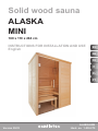
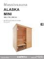
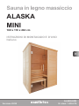
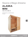
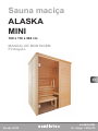
Solid wood sauna
ALASKA
MINI
160 x 110 x 204 cm

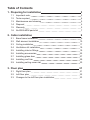
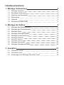
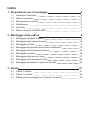
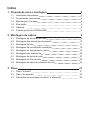
Table of Contents
1. Preparing for installation 3
1.1. Important note: 3
1.2. Tools required 4
1.3. Maintenance and cleaning 5
1.4. Disposal 5
1.5. Warranty 5
1.6. ALASKA MINI parts list 7
2. Cabin installation 9
2.1. Base frame installation 9
2.2. Wall element installation 10
2.3. Ceiling installation 17
2.4. Ventilation slit installation 19
2.5. Installinginteriorttings 19
2.6. Installing accessories 25
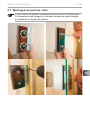
2.7. Installing glass door 27
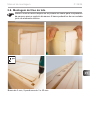
2.8. Installing roof trim 29
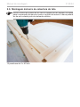
2.9. Installing ceiling cover slat 30
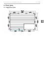
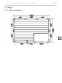
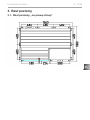
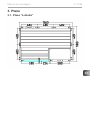
3. Floor plan 31
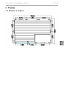
3.1. Rightoorplan 31
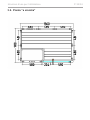
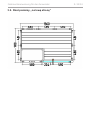
3.2. Leftoorplan 32
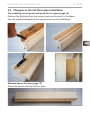
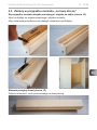
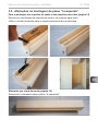
3.3. Changestotheleftoorplaninstallation 33

EN
Instructions for installation and use p. 3/34
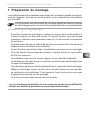
1. Preparing for installation
Read these installation instructions carefully and keep them within reach when
using the sauna, so that you can look up product information at any time.
Attention!
The electrical connection may only be performed by a qualied electrician
or similarly trained person.
These installation instructions can also be found in the downloads section
of our website: www.sentiotec.com/downloads.
1.1. Important note:
●Before you begin work, check the parts list to ensure that all the individual
parts have been delivered. If you discover any missing parts, notify your
dealer within 14 days of receiving the sauna cabin.
●The room that the sauna is installed in must be dry and ensure an appropriate
amount of air circulation.
● Theoormustbelevelandeven,preferablyastoneortiledoor.
●A minimum room height of 230 cm is required for the cabin installation work.
●A distance of at least 5 cm from the wall must be maintained.
●The inside of the wooden parts used must not be treated with any impreg-
nating material.
●You need an assistant for the installation.
●Wood is a natural product that can swell, shrink or warp, despite good stor-
age. For this reason, some force may be necessary during the installation.
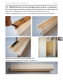
● Allscrewttingsmustbepre-drilled.

Instructions for installation and use p. 4/34
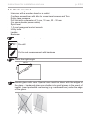
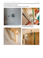
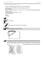
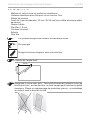
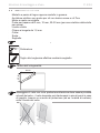
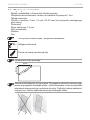
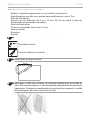
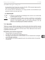
This symbol indicates tips and useful information
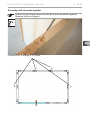
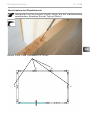
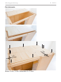
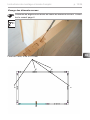
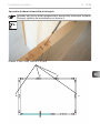
Pre-drill
Cut to real measurement with backsaw
Check the right angle:
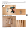
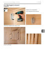
1.2. Tools required
●Hammer with a wooden head or a mallet
●Cordless screwdriver with bits for cross-head screws and Torx
●Roller tape measure
●Drill bits with a diameter of 3 mm, 10 mm, 20 - 30 mm
(for sauna heater power cable)
●Spirit level
●1.5 mm hexagonal socket wrench
●Utility knife
●Ladder
●Backsaw
60 cm
80 cm
100 cm
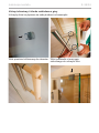
Handle glass with care: Special care must be taken with the edges of
the glass – hardened glass can shatter into small pieces in the event of
impact. Insert protective cushioning (e.g: cardboard box) under the edge
of the glass.

EN
Instructions for installation and use p. 5/34
1.3. Maintenance and cleaning
●The sauna should be cleaned with a damp cloth. Only use warm water – no
cleaning products.
●We recommend heating the cabin once a month if the sauna is not used for
a long time.
1.4. Disposal
●Please dispose of packaging materials in accordance with the
applicable disposal regulations.
●Used appliances contain reusable materials as well as hazardous
substances. Therefore, do not dispose of your used appliance with
household waste, but rather do so in accordance with the locally
applicable regulations.
1.5. Warranty
Weprovideave-yearwarrantyonallofoursolidwoodandelementcabinsof
the line sentiotec sauna and sentiotec infra for private usage. For commercial
usage, the warranty is two years. For cabins of the hotline series, the warranty
is two years.
Requirement for this warranty:
• The corresponding invoice is presented,
• a detailed description of the defect is enclosed,
• the cabins were installed in accordance with the sentiotec installation and
operating instructions,
• the warranty claim is received by sentiotec within the warranty period.

Instructions for installation and use p. 6/34
Excluded from the warranty are:
• Decienciesordamagethatiscausedbynon-intendeduse
• Cabinsthatweremodiedwithouttheexplicitapprovalofthemanufacturer
• Pitch pockets
• Pitch leaking out
• Damage and discolouration of the wood due to inadequate ventilation or
a non-intended installation site
• Natural changes in the wood such as discolouration, crack formation, shrink-
age, swelling or similar changes due to the natural properties of the wood
Pitch pockets are not grounds for return, since they can always appear in spruce
wood and the depth at which they lie cannot be detected during the sorting out
process. If these are just under the surface, heat can cause them to soften and
“bleed”. Remove leaking pitch with a rag soaked in acetone. If only droplets of
pitch occur, allow these to harden and then carefully scrape them off with a knife.
The warranty period starts from the date of invoice of the cabin manufacturer.
A requirement is the presentation of the original invoice. If no original invoice
is available, the month of manufacture, noted on the nameplate of the product,
is used as the basis for the start of the warranty period. The warranty period is
neither extended nor renewed by warranty services.
Theve-yearwarrantyisanadditiontothetermsandconditionsofsentiotec
GmbH.

EN
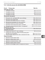
Instructions for installation and use p. 7/34
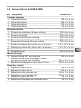
Base frame
1 Base frame 156 x 9 x 4 cm
1 Base frame 108 x 9 x 4 cm
1 Base frame 102 x 9 x 4 cm
1 Base frame 64 x 9 x 4 cm
Wall elements
1 A/B ventilation element with Multiclip 193 x 48 x 4 cm
1 A/B wall element 193 x 48 x 4 cm
1 A/B wall element with Multiclip 193 x 48 x 4 cm
4 A/A wall elements with Multiclip 193 x 48 x 4 cm
1 A/A electrical element with Multiclip 193 x 58 x 4 cm
1Elementabovedoor,oorplan(right) 81.5 x 10.1 x 4 cm
1Elementabovedoor,oorplan(left) 81.5 x 10.1 x 4 cm
Ceiling elements
2 Ceiling elements 146 x 49 x 4 cm
Corner posts
3 90° corner posts with Multiclip 193 x 6 x 6 cm
1
Corner post with front hinge for glass door with Multiclip
202 x 6 x 7.5 cm
1 Post for glass element, 8 mm groove 202 x 4.5 x 4 cm
Support slats
2 Roof support slats 140 x 4 x 4 cm
2 Roof support slats 100 x 4 x 4 cm
2 Roof cover slats 144 x 1.2 x 4 cm
2 Roof cover slats 104 x 1.2 x 4 cm
2 Bench support slats 58 x 4 x 4 cm
2 Mounting slats for bench screen 26 x 4 x 4 cm
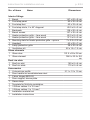
No. of items Name Dimensions
1.6. ALASKA MINI parts list

Instructions for installation and use p. 8/34
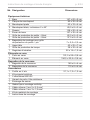
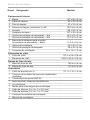
No. of items Name Dimensions
Interior ttings
1 Bench 147 x 62 x 9 cm
1 Foot step panel 80 x 35 x 9 cm
2 Foot step feet 43 x 33 x 4 cm
2 Foot step struts, 2 x 45° diagonal 49.5 x 8 x 2 cm
1 Backrests 138 x 26 x 4 cm
1 Bench screen 147 x 35 x 4 cm
1 Heater protection grille – lime wood 62.5 x 8 x 2 cm
1 Heater protection grille – lime wood 37.5 x 8 x 2 cm
3
Mounting slats for heater protection grille – spruce
7 x 2.5 x 2.5 cm
1 Headrest 43 x 25 x 7 cm
1 Lamp protection grille 38 x 32 x 4 cm
1 Ventilation slit 52 x 14 x 1.5 cm
Glass elements
1 Glass door
191.5 x 59 x 0.8 cm
1 Glass element
194.5 x 22.4 x 0.8
cm
Roof rim slats
1 Roof rim slat 160 x 6 x 4 cm
2 Roof rim slats 115 x 6 x 4 cm
Accessories
1Ualuminiumprole
21.1 x 1.2 x 1.5 cm
1 Door handle set wood/stainless steel
1 2 door hinges 8653-02
1 Door magnet, sleeve plate
1 Sauna lamp
1 Template for Multiclip installation
1 3 Silicon cables: 5 x 2.5 mm²
1 3 Silicon cables: 3 x 1.5 mm²
1 Installation material set
1 Installation instructions

EN
Instructions for installation and use p. 9/34
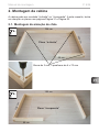
2. Cabin installation
Thecabincanhavearightorleftsetup,pleasenotethecorrespondingoor
plans on Page 31 and Page 32.
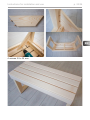
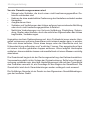
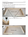
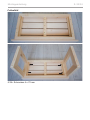
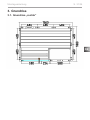
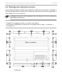
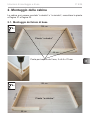
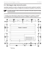
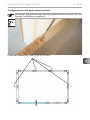
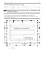
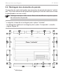
2.1. Base frame installation
Right oor plan
Left oor plan
156 cm
64 cm
102 cm
108 cm
102 cm
108 cm
156 cm
64 cm
3 mm drill bit, 3 screws 4 x 70 mm

Instructions for installation and use p. 10/34
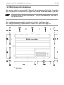
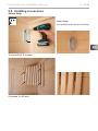
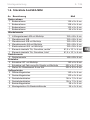
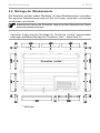
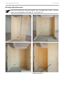
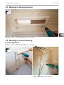
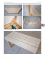
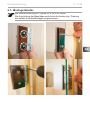
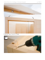
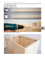
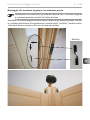
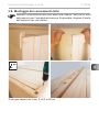
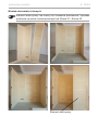
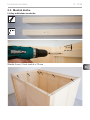
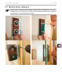
2.2. Wall element installation
The corner posts are connected to the wall elements using Multiclips. The other
wall elements are connected by tongue and groove and are screwed together.
Right oor plan
*
*
* *
*
*
* Multiclips
Attention!
Theinstallationsubsequentlydescribedisfortherightoorplan.
ForchangesaffectinginstallationfortheleftoorplanseePage33.
* *
A always refers to the visible side. This is labelled on the top side of
the wall elements.

EN
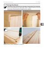
Instructions for installation and use p. 11/34
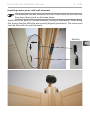
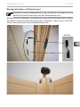
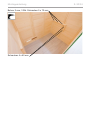
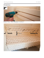
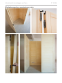
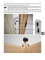
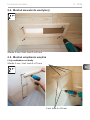
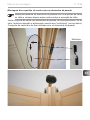
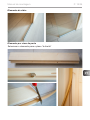
Pre-assemblethewallelementswiththecornerpostsontheoorand
then place these posts on the base frame.
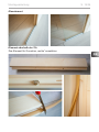
Insert the corner post on the wall elements, moving it downwards. When doing
this, ensure that the Multiclips are correctly aligned (see below). The corner post
mustbeushwiththewallelements.
Multiclip
Installing corner posts with wall elements

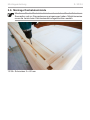
Instructions for installation and use p. 12/34
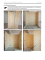
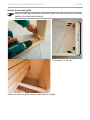
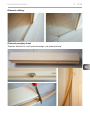
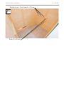
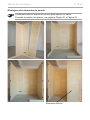
Installing wall elements
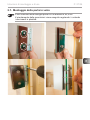
Electrical element
The electrical element has drill holes for laying cables. For the position,
seeoorplansonPage31andPage32.

EN
Instructions for installation and use p. 13/34
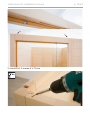
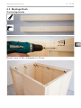
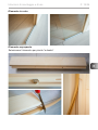
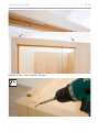
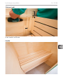
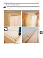
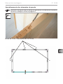
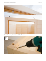
Screwing wall elements together
3 mm drill bit, 4 screws 4 x 70 mm
Check the right angle before screwing the wall elements together.
Observe the tip on page 4.

Instructions for installation and use p. 14/34
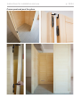
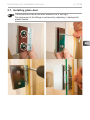
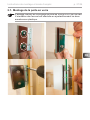
Corner post and post for glass

EN
Instructions for installation and use p. 15/34
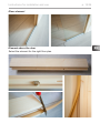
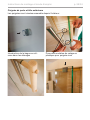
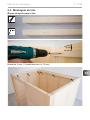
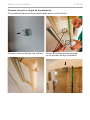
Glass element
Element above the door
Selecttheelementfortherightoorplan

Instructions for installation and use p. 16/34
3 mm drill bit, 2 screws 4 x 70 mm

EN
Instructions for installation and use p. 17/34
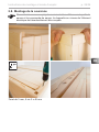
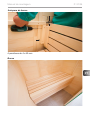
2.3. Ceiling installation
Roof support slats
4 cm
3 mm drill bit, 12 screws 4 x 70 mm

Instructions for installation and use p. 18/34
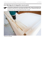
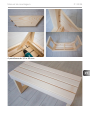
Ceiling elements
3 mm drill bit, 10 screws 4 x 70 mm
1 cm
1 cm

EN
Instructions for installation and use p. 19/34
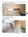
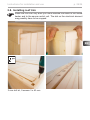
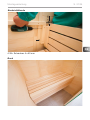
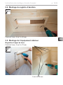
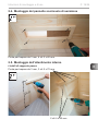
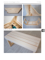
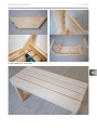
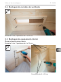
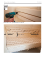
2.4. Ventilation slit installation
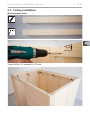
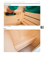
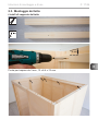
2.5. Installing interior ttings
Bench support slats
2 screws 4 x 60 mm
3 mm drill bit, 3 screws 5 x 70 mm
3 mm drill bit, 4 screws 3 x 40 mm
82 cm

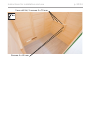
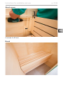
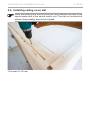
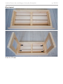
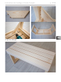
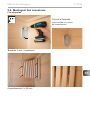
Instructions for installation and use p. 20/34
3 mm drill bit, 3 screws 5 x 70 mm
Screws 4 x 60 mm
Strona się ładuje...
Strona się ładuje...
Strona się ładuje...
Strona się ładuje...
Strona się ładuje...
Strona się ładuje...
Strona się ładuje...
Strona się ładuje...
Strona się ładuje...
Strona się ładuje...
Strona się ładuje...
Strona się ładuje...
Strona się ładuje...
Strona się ładuje...
Strona się ładuje...
Strona się ładuje...
Strona się ładuje...
Strona się ładuje...
Strona się ładuje...
Strona się ładuje...
Strona się ładuje...
Strona się ładuje...
Strona się ładuje...
Strona się ładuje...
Strona się ładuje...
Strona się ładuje...
Strona się ładuje...
Strona się ładuje...
Strona się ładuje...
Strona się ładuje...
Strona się ładuje...
Strona się ładuje...
Strona się ładuje...
Strona się ładuje...
Strona się ładuje...
Strona się ładuje...
Strona się ładuje...
Strona się ładuje...
Strona się ładuje...
Strona się ładuje...
Strona się ładuje...
Strona się ładuje...
Strona się ładuje...
Strona się ładuje...
Strona się ładuje...
Strona się ładuje...
Strona się ładuje...
Strona się ładuje...
Strona się ładuje...
Strona się ładuje...
Strona się ładuje...
Strona się ładuje...
Strona się ładuje...
Strona się ładuje...
Strona się ładuje...
Strona się ładuje...
Strona się ładuje...
Strona się ładuje...
Strona się ładuje...
Strona się ładuje...
Strona się ładuje...
Strona się ładuje...
Strona się ładuje...
Strona się ładuje...
Strona się ładuje...
Strona się ładuje...
Strona się ładuje...
Strona się ładuje...
Strona się ładuje...
Strona się ładuje...
Strona się ładuje...
Strona się ładuje...
Strona się ładuje...
Strona się ładuje...
Strona się ładuje...
Strona się ładuje...
Strona się ładuje...
Strona się ładuje...
Strona się ładuje...
Strona się ładuje...
Strona się ładuje...
Strona się ładuje...
Strona się ładuje...
Strona się ładuje...
Strona się ładuje...
Strona się ładuje...
Strona się ładuje...
Strona się ładuje...
Strona się ładuje...
Strona się ładuje...
Strona się ładuje...
Strona się ładuje...
Strona się ładuje...
Strona się ładuje...
Strona się ładuje...
Strona się ładuje...
Strona się ładuje...
Strona się ładuje...
Strona się ładuje...
Strona się ładuje...
Strona się ładuje...
Strona się ładuje...
Strona się ładuje...
Strona się ładuje...
Strona się ładuje...
Strona się ładuje...
Strona się ładuje...
Strona się ładuje...
Strona się ładuje...
Strona się ładuje...
Strona się ładuje...
Strona się ładuje...
Strona się ładuje...
Strona się ładuje...
Strona się ładuje...
Strona się ładuje...
Strona się ładuje...
Strona się ładuje...
Strona się ładuje...
Strona się ładuje...
Strona się ładuje...
Strona się ładuje...
Strona się ładuje...
Strona się ładuje...
Strona się ładuje...
Strona się ładuje...
Strona się ładuje...
Strona się ładuje...
Strona się ładuje...
Strona się ładuje...
Strona się ładuje...
Strona się ładuje...
Strona się ładuje...
Strona się ładuje...
Strona się ładuje...
Strona się ładuje...
Strona się ładuje...
Strona się ładuje...
Strona się ładuje...
Strona się ładuje...
Strona się ładuje...
Strona się ładuje...
Strona się ładuje...
Strona się ładuje...
Strona się ładuje...
Strona się ładuje...
Strona się ładuje...
Strona się ładuje...
Strona się ładuje...
Strona się ładuje...
Strona się ładuje...
Strona się ładuje...
Strona się ładuje...
Strona się ładuje...
Strona się ładuje...
Strona się ładuje...
Strona się ładuje...
Strona się ładuje...
Strona się ładuje...
Strona się ładuje...
Strona się ładuje...
Strona się ładuje...
Strona się ładuje...
Strona się ładuje...
Strona się ładuje...
Strona się ładuje...
Strona się ładuje...
Strona się ładuje...
Strona się ładuje...
Strona się ładuje...
Strona się ładuje...
Strona się ładuje...
Strona się ładuje...
Strona się ładuje...
Strona się ładuje...
Strona się ładuje...
Strona się ładuje...
Strona się ładuje...
Strona się ładuje...
Strona się ładuje...
Strona się ładuje...
Strona się ładuje...
Strona się ładuje...
Strona się ładuje...
Strona się ładuje...
Strona się ładuje...
Strona się ładuje...
Strona się ładuje...
-
 1
1
-
 2
2
-
 3
3
-
 4
4
-
 5
5
-
 6
6
-
 7
7
-
 8
8
-
 9
9
-
 10
10
-
 11
11
-
 12
12
-
 13
13
-
 14
14
-
 15
15
-
 16
16
-
 17
17
-
 18
18
-
 19
19
-
 20
20
-
 21
21
-
 22
22
-
 23
23
-
 24
24
-
 25
25
-
 26
26
-
 27
27
-
 28
28
-
 29
29
-
 30
30
-
 31
31
-
 32
32
-
 33
33
-
 34
34
-
 35
35
-
 36
36
-
 37
37
-
 38
38
-
 39
39
-
 40
40
-
 41
41
-
 42
42
-
 43
43
-
 44
44
-
 45
45
-
 46
46
-
 47
47
-
 48
48
-
 49
49
-
 50
50
-
 51
51
-
 52
52
-
 53
53
-
 54
54
-
 55
55
-
 56
56
-
 57
57
-
 58
58
-
 59
59
-
 60
60
-
 61
61
-
 62
62
-
 63
63
-
 64
64
-
 65
65
-
 66
66
-
 67
67
-
 68
68
-
 69
69
-
 70
70
-
 71
71
-
 72
72
-
 73
73
-
 74
74
-
 75
75
-
 76
76
-
 77
77
-
 78
78
-
 79
79
-
 80
80
-
 81
81
-
 82
82
-
 83
83
-
 84
84
-
 85
85
-
 86
86
-
 87
87
-
 88
88
-
 89
89
-
 90
90
-
 91
91
-
 92
92
-
 93
93
-
 94
94
-
 95
95
-
 96
96
-
 97
97
-
 98
98
-
 99
99
-
 100
100
-
 101
101
-
 102
102
-
 103
103
-
 104
104
-
 105
105
-
 106
106
-
 107
107
-
 108
108
-
 109
109
-
 110
110
-
 111
111
-
 112
112
-
 113
113
-
 114
114
-
 115
115
-
 116
116
-
 117
117
-
 118
118
-
 119
119
-
 120
120
-
 121
121
-
 122
122
-
 123
123
-
 124
124
-
 125
125
-
 126
126
-
 127
127
-
 128
128
-
 129
129
-
 130
130
-
 131
131
-
 132
132
-
 133
133
-
 134
134
-
 135
135
-
 136
136
-
 137
137
-
 138
138
-
 139
139
-
 140
140
-
 141
141
-
 142
142
-
 143
143
-
 144
144
-
 145
145
-
 146
146
-
 147
147
-
 148
148
-
 149
149
-
 150
150
-
 151
151
-
 152
152
-
 153
153
-
 154
154
-
 155
155
-
 156
156
-
 157
157
-
 158
158
-
 159
159
-
 160
160
-
 161
161
-
 162
162
-
 163
163
-
 164
164
-
 165
165
-
 166
166
-
 167
167
-
 168
168
-
 169
169
-
 170
170
-
 171
171
-
 172
172
-
 173
173
-
 174
174
-
 175
175
-
 176
176
-
 177
177
-
 178
178
-
 179
179
-
 180
180
-
 181
181
-
 182
182
-
 183
183
-
 184
184
-
 185
185
-
 186
186
-
 187
187
-
 188
188
-
 189
189
-
 190
190
-
 191
191
-
 192
192
-
 193
193
-
 194
194
-
 195
195
-
 196
196
-
 197
197
-
 198
198
-
 199
199
-
 200
200
-
 201
201
-
 202
202
-
 203
203
-
 204
204
-
 205
205
-
 206
206
-
 207
207
-
 208
208


w innych językach
- italiano: Sentiotec ALASKA MINI Manuale utente
- português: Sentiotec ALASKA MINI Manual do usuário
- français: Sentiotec ALASKA MINI Manuel utilisateur
Powiązane artykuły
-
Sentiotec Alaska Mini Infra+ Instrukcja obsługi
-
-
-
-
-
-
-
-
-