Installation Instructions
Original Instructions
CompactLogix 5480 Controller
Catalog Number
5069-L46ERMW
The CompactLogix™ 5480 controllers can operate in various applications, including the use of local Compact 5000™ I/O modules and
remote I/O modules and Integrated Motion over an EtherNet/IP network. The controllers offer the following:
• A Logix-based real-time controller that runs an instance of Windows 10 IoT Enterprise, also known as a commercial operating
system (COS)
• High-speed bus packet transfer rate
• High-speed I/O module communication, motion control, and use of Device Level Ring (DLR), Linear and Star EtherNet/IP topologies
• Multiple ports for use with the Logix control engine on the controller, including:
– One USB programming port for temporary connection
– Three Gigabit Ethernet ports for high-speed I/O communication and motion control
• Multiple ports for use with the COS on the controller, including:
– One Gigabit Ethernet port as a dedicated OS network interface
– An integrated DisplayPort for high definition monitor connectivity
– Two USB 3.0 ports for OS peripheral and expanded data storage capability
You use the Studio 5000 Logix Designer® application to configure CompactLogix 5480 controllers.
For more information on the components that are required to install a CompactLogix 5480 controller, see
page 5. For more information on how to
use the controller after you install it, see the publications that are listed in
Additional Resources on page 23.
Topic Page
About the Controller 4
Required System Components 5
Install the Controller onto the DIN Rail 8
Connect External Power Supplies to the Controller 8
Connect Control Signals Via UPS Control RTB 12
Install Compact 5000 I/O Modules 16
Install the End Cap 16
Power the System 16
Set the Network Internet Protocol (IP) Addresses 17
Connect the Controller to an EtherNet/IP Network 17
Remove and Replace the Controller 18
Replace the Fans 19
Specifications 22
Additional Resources 23

2 Rockwell Automation Publication 5069-IN019C-EN-P - October 2018
CompactLogix 5480 Controller
ATTENTION: Read this document and the documents listed in the Additional Resources section about installation, configuration and operation of this equipment before you install, configure, operate or maintain
this product. Users are required to familiarize themselves with installation and wiring instructions in addition to requirements of all applicable codes, laws, and standards.
Activities including installation, adjustments, putting into service, use, assembly, disassembly, and maintenance are required to be carried out by suitably trained personnel in accordance with applicable code of
practice.
If this equipment is used in a manner not specified by the manufacturer, the protection provided by the equipment may be impaired.
⌘˖൘ᆹ㻵ǃ䝽㖞ǃ઼㔤ᣔᵜӗ૱ࡽˈ䈧䰵䈫ᵜ᮷ẓԕ৺ Ā ަԆ䍴Ⓚ ā 䜘࠶ࡇࠪⲴᴹޣ䇮༷ᆹ㻵ǃ䝽㖞઼Ⲵᓄ᮷ẓDŽ䲔Ҷᡰᴹ䘲⭘㿴㤳ǃ⌅ᖻ
઼ḷ߶Ⲵޣ㾱≲ѻཆˈ⭘ᡧ䘈ᗵ享⟏ᚹᆹ㻵઼᧕㓯䈤᰾DŽ
ᆹ㻵ǃ䈳ᮤǃᣅ䘀ǃ֯⭘ǃ㓴㻵ǃন઼㔤ᣔㅹ亩ᗵ享⭡㓿䗷䘲ᖃ䇝㓳ⲴуъӪઈ᤹➗䘲⭘Ⲵ㿴㤳ᇎᯭDŽ
ྲ᷌ᵚ᤹➗ࡦ䙐୶ᤷᇊⲴᯩᔿ֯⭘䈕䇮༷ˈࡉਟ㜭Պᦏᇣ䇮༷ᨀⲴ؍ᣔDŽ
ATENCIÓN: Antes de instalar, configurar, poner en funcionamiento o realizar el mantenimiento de este producto, lea este documento y los documentos listados en la sección Recursos adicionales acerca de la
instalación, configuración y operación de este equipo. Los usuarios deben familiarizarse con las instrucciones de instalación y cableado y con los requisitos de todos los códigos, leyes y estándares vigentes.
El personal debidamente capacitado debe realizar las actividades relacionadas a la instalación, ajustes, puesta en servicio, uso, ensamblaje, desensamblaje y mantenimiento de conformidad con el código de
práctica aplicable.
Si este equipo se usa de una manera no especificada por el fabricante, la protección provista por el equipo puede resultar afectada.
ATENÇÃO: Leia este e os demais documentos sobre instalação, configuração e operação do equipamento que estão na seção Recursos adicionais antes de instalar, configurar, operar ou manter este produto. Os
usuários devem se familiarizar com as instruções de instalação e fiação além das especificações para todos os códigos, leis e normas aplicáveis.
É necessário que as atividades, incluindo instalação, ajustes, colocação em serviço, utilização, montagem, desmontagem e manutenção sejam realizadas por pessoal qualificado e especializado, de acordo com o
código de prática aplicável.
Caso este equipamento seja utilizado de maneira não estabelecida pelo fabricante, a proteção fornecida pelo equipamento pode ficar prejudicada.
ВНИМАНИЕ: Перед тем как устанавливать, настраивать, эксплуатировать или обслуживать данное оборудование, прочитайте этот документ и документы, перечисленные в разделе
«Дополнительные ресурсы». В этих документах изложены сведения об установке, настройке и эксплуатации данного оборудования. Пользователи обязаны ознакомиться с инструкциями по
установке и прокладке соединений, а также с требованиями всех применимых норм, законов и стандартов.
Все действия, включая установку, наладку, ввод в эксплуатацию, использование, сборку, разборку и техническое обслуживание, должны выполняться обученным персоналом в соответствии с
применимыми нормами и правилами.
Если оборудование используется не предусмотренным производителем образом, защита оборудования может быть нарушена.
ὀព ᮏ〇ရࢆタ⨨ࠊᵓᡂࠊ✌ືࡲࡓࡣಖᏲࡍࡿ๓ࠊᮏ᭩࠾ࡼࡧᮏᶵჾࡢタ⨨ࠊタᐃࠊ᧯సࡘ࠸࡚ࡢཧ⪃㈨ᩱࡢヱᙜ⟠ᡤグ㍕ࡉࢀ࡚࠸ࡿᩥ᭩┠ࢆ
㏻ࡋ࡚ࡃࡔࡉ࠸ࠋ࣮ࣘࢨࡣࠊࡍ࡚ࡢヱᙜࡍࡿ᮲ࠊἲᚊࠊつ᱁ࡢせ௳ຍ࠼࡚ࠊタ⨨࠾ࡼࡧ㓄⥺ࡢᡭ㡰⩦⇍ࡋ࡚࠸ࡿᚲせࡀ࠶ࡾࡲࡍࠋ
タ⨨ㄪᩚࠊ㐠㌿ࡢ㛤ጞࠊ⏝ࠊ⤌❧࡚ࠊゎయࠊಖᏲࢆྵࡴㅖసᴗࡣࠊヱᙜࡍࡿᐇつ๎ᚑࡗ࡚カ⦎ࢆཷࡅࡓ㐺ษ࡞సᴗဨࡀᐇ⾜ࡍࡿᚲせࡀ࠶ࡾࡲࡍࠋ
ᮏᶵჾࡀ〇㐀࣓࣮࢝ࡼࡾᣦᐃࡉࢀ࡚࠸࡞࠸᪉ἲ࡛⏝ࡉࢀ࡚࠸ࡿሙྜࠊᶵჾࡼࡾᥦ౪ࡉࢀ࡚࠸ࡿಖㆤࡀᦆ࡞ࢃࢀࡿᜍࢀࡀ࠶ࡾࡲࡍࠋ
ACHTUNG: Lesen Sie dieses Dokument und die im Abschnitt „Weitere Informationen“aufgeführten Dokumente, die Informationen zu Installation, Konfiguration und Bedienung dieses Produkts enthalten, bevor
Sie dieses Produkt installieren, konfigurieren, bedienen oder warten. Anwender müssen sich neben den Bestimmungen aller anwendbaren Vorschriften, Gesetze und Normen zusätzlich mit den Installations- und
Verdrahtungsanweisungen vertraut machen.
Arbeiten im Rahmen der Installation, Anpassung, Inbetriebnahme, Verwendung, Montage, Demontage oder Instandhaltung dürfen nur durch ausreichend geschulte Mitarbeiter und in Übereinstimmung mit den
anwendbaren Ausführungsvorschriften vorgenommen werden.
Wenn das Gerät in einer Weise verwendet wird, die vom Hersteller nicht vorgesehen ist, kann die Schutzfunktion beeinträchtigt sein.
ATTENTION : Lisez ce document et les documents listés dans la section Ressources complémentaires relatifs à l’installation, la configuration et le fonctionnement de cet équipement avant d’installer, configurer,
utiliser ou entretenir ce produit. Les utilisateurs doivent se familiariser avec les instructions d’installation et de câblage en plus des exigences relatives aux codes, lois et normes en vigueur.
Les activités relatives à l’installation, le réglage, la mise en service, l’utilisation, l’assemblage, le démontage et l’entretien doivent être réalisées par des personnes formées selon le code de pratique en vigueur.
Si cet équipement est utilisé d’une façon qui n’a pas été définie par le fabricant, la protection fournie par l’équipement peut être compromise.
㭒㦮 a ⽎G㩲䛞G㍺䂮 SG㍺㩫 SG㧧☯G⡦⓪G㥶㰖G⽊㑮䞮₆G㩚㠦G⽎Gⶎ㍲⯒G䙂䞾䞮㡂G㍺䂮 SG㍺㩫GG㧧☯㠦Gὖ䞲G㺎ἶG㧦⬢G㎏㎮㦮Gⶎ㍲✺㦚G✲㔲G㧓ἶG㑯㰖䞮㕃
㔲㡺 UG㌂㣿㧦⓪G⳾✶Gὖ⩾G′㩫 SG⻫′GG䚲㭖㠦㍲G㣪ῂ䞮⓪G㌂䟃㠦G╖䟊G✲㔲G㍺䂮GG⺆㍶G㰖䂾㦚G㑯㰖䟊㟒G䞿┞┺ U
㍺䂮 SG㫆㩫 SGṖ☯ SG㌂㣿 SG㫆Ⱃ SG䟊 SG㥶㰖⽊㑮G❇G⳾✶G㧧㠛㦖Gὖ⩾G′㩫㠦G➆⧒G㩗㩞䞲Gᾦ㥷㦚G㦖G㌂㣿㧦⯒G䐋䟊㍲ⰢG㑮䟟䟊㟒G䞿┞┺ U
⽎G㧻゚⯒G㩲㫆㌂ṖGⳛ㔲䞮㰖G㞠㦖G⻫㦒⪲G㌂㣿䞮ⳊG㧻゚㦮G⽊䢎G₆⓻㧊G㏦㌗♶G㑮G㧞㔋┞┺ U
ATTENZIONE Prima di installare, configurare ed utilizzare il prodotto, o effettuare interventi di manutenzione su di esso, leggere il presente documento ed i documenti elencati nella sezione “Altre risorse”,
riguardanti l’installazione, la configurazione ed il funzionamento dell’apparecchiatura. Gli utenti devono leggere e comprendere le istruzioni di installazione e cablaggio, oltre ai requisiti previsti dalle leggi, codici
e standard applicabili.
Le attività come installazione, regolazioni, utilizzo, assemblaggio, disassemblaggio e manutenzione devono essere svolte da personale adeguatamente addestrato, nel rispetto delle procedure previste.
Qualora l’apparecchio venga utilizzato con modalità diverse da quanto previsto dal produttore, la sua funzione di protezione potrebbe venire compromessa.
DİKKAT: Bu ürünün kurulumu, yapılandırılması, işletilmesi veya bakımı öncesinde bu dokümanı ve bu ekipmanın kurulumu, yapılandırılması ve işletimi ile ilgili İlave Kaynaklar bölümünde yer listelenmiş
dokümanları okuyun. Kullanıcılar yürürlükteki tüm yönetmelikler, yasalar ve standartların gereksinimlerine ek olarak kurulum ve kablolama talimatlarını da öğrenmek zorundadır.
Kurulum, ayarlama, hizmete alma, kullanma, parçaları birleştirme, parçaları sökme ve bakım gibi aktiviteler sadece uygun eğitimleri almış kişiler tarafından yürürlükteki uygulama yönetmeliklerine uygun şekilde
yapılabilir.
Bu ekipman üretici tarafından belirlenmiş amacın dışında kullanılırsa, ekipman tarafından sağlanan koruma bozulabilir.
⌘һ丵˖൘ᆹ㼍ǃ䁝ᇊǃᡆ㏝䆧ᵜ⭒૱ࡽˈ䃻ݸ䯡䆰↔᮷Ԧԕ৺ࡇᯬ NjަԆ䋷Ⓚnjㄐㇰѝᴹ䰌ᆹ㼍ǃ䁝ᇊ㠷↔䁝ۉⲴ᮷ԦDŽ֯⭘㘵ᗵ丸⟏ᚹᆹ㼍઼
䝽㐊ᤷ⽪ˈіㅖਸᡰᴹ⌅㾿ǃ⌅ᖻ઼⁉Ⓠ㾱≲DŽ
वᤜᆹ㼍ǃ䃯ᮤǃӔԈ֯⭘ǃ֯⭘ǃ㍴㼍ǃন઼㏝䆧ㅹअ䜭ᗵ丸Ӕ⭡ᐢ㏃䙾䚙⮦䁃㐤ⲴӪ䙢㹼ˈԕㅖਸ䚙⭘Ⲵሖ⌅㾿DŽ
ྲ᷌ሷ䁝ۉ⭘ᯬ䶎㼭䙐୶ᤷᇊⲴ⭘䙄ᱲˈਟ㜭ᴳ䙐ᡀ䁝ۉᡰᨀⲴ؍䆧࣏㜭ਇᨽDŽ
POZOR: Než začnete instalovat, konfigurovat či provozovat tento výrobek nebo provádět jeho údržbu, přečtěte si tento dokument a dokumenty uvedené v části Dodatečné zdroje ohledně instalace, konfigurace
a provozu tohoto zařízení. Uživatelé se musejí vedle požadavků všech relevantních vyhlášek, zákonů a norem nutně seznámit také s pokyny pro instalaci a elektrické zapojení.
Činnosti zahrnující instalaci, nastavení, uvedení do provozu, užívání, montáž, demontáž a údržbu musí vykonávat vhodně proškolený personál v souladu s příslušnými prováděcími předpisy.
Pokud se toto zařízení používá způsobem neodpovídajícím specifikaci výrobce, může být narušena ochrana, kterou toto zařízení poskytuje.
UWAGA: Przed instalacją, konfiguracją, użytkowaniem lub konserwacją tego produktu należy przeczytać niniejszy dokument oraz wszystkie dokumenty wymienione w sekcji Dodatkowe źródła omawiające
instalację, konfigurację i procedury użytkowania tego urządzenia. Użytkownicy mają obowiązek zapoznać się z instrukcjami dotyczącymi instalacji oraz oprzewodowania, jak również z obowiązującymi kodeksami,
prawem i normami.
Działania obejmujące instalację, regulację, przekazanie do użytkowania, użytkowanie, montaż, demontaż oraz konserwację muszą być wykonywane przez odpowiednio przeszkolony personel zgodnie z
obowiązującym kodeksem postępowania.
Jeśli urządzenie jest użytkowane w sposób inny niż określony przez producenta, zabezpieczenie zapewniane przez urządzenie może zostać ograniczone.
OBS! Läs detta dokument samt dokumentet, som står listat i avsnittet Övriga resurser, om installation, konfigurering och drift av denna utrustning innan du installerar, konfigurerar eller börjar använda eller utföra
underhållsarbete på produkten. Användare måste bekanta sig med instruktioner för installation och kabeldragning, förutom krav enligt gällande koder, lagar och standarder.
Åtgärder som installation, justering, service, användning, montering, demontering och underhållsarbete måste utföras av personal med lämplig utbildning enligt lämpligt bruk.
Om denna utrustning används på ett sätt som inte anges av tillverkaren kan det hända att utrustningens skyddsanordningar försätts ur funktion.
LET OP: Lees dit document en de documenten die genoemd worden in de paragraaf Aanvullende informatie over de installatie, configuratie en bediening van deze apparatuur voordat u dit product installeert,
configureert, bediend of onderhoudt. Gebruikers moeten zich vertrouwd maken met de installatie en de bedradingsinstructies, naast de vereisten van alle toepasselijke regels, wetten en normen.
Activiteiten zoals het installeren, afstellen, in gebruik stellen, gebruiken, monteren, demonteren en het uitvoeren van onderhoud mogen uitsluitend worden uitgevoerd door hiervoor opgeleid personeel en in
overeenstemming met de geldende praktijkregels.
Indien de apparatuur wordt gebruikt op een wijze die niet is gespecificeerd door de fabrikant, dan bestaat het gevaar dat de beveiliging van de apparatuur niet goed werkt.

Rockwell Automation Publication 5069-IN019C-EN-P - October 2018 3
CompactLogix 5480 Controller
Environment and Enclosure
ATTENTION: This equipment is intended for use in a Pollution Degree 2 industrial environment, in overvoltage Category II applications (as defined in EN/IEC
60664-1), at altitudes up to 2000 m (6562 ft) without derating.
This equipment is not intended for use in residential environments and may not provide adequate protection to radio communication services in such
environments.
This equipment is supplied as open-type equipment for indoor use. It must be mounted within an enclosure that is suitably designed for those specific
environmental conditions that will be present and appropriately designed to prevent personal injury resulting from accessibility to live parts. The enclosure must
have suitable flame-retardant properties to prevent or minimize the spread of flame, complying with a flame spread rating of 5VA or be approved for the
application if nonmetallic. The interior of the enclosure must be accessible only by the use of a tool. Subsequent sections of this publication may contain more
information regarding specific enclosure type ratings that are required to comply with certain product safety certifications.
In addition to this publication, see the following:
• Industrial Automation Wiring and Grounding Guidelines, publication
1770-4.1, for more installation requirements.
• NEMA 250 and EN/IEC 60529, as applicable, for explanations of the degrees of protection provided by enclosures.
Prevent Electrostatic Discharge
ATTENTION: This equipment is sensitive to electrostatic discharge, which can cause internal damage and affect normal operation. Follow these guidelines when
you handle this equipment:
• Touch a grounded object to discharge potential static.
• Wear an approved grounding wriststrap.
• Do not touch connectors or pins on component boards.
• Do not touch circuit components inside the equipment.
• Use a static-safe workstation, if available.
• Store the equipment in appropriate static-safe packaging when not in use.
ATTENTION:
• In case of malfunction or damage, no attempts at repair should be made. The controller should be returned to the manufacturer for repair. Do not dismantle
the controller.
• This equipment is certified for use only within the surrounding air temperature range of 0…60 °C (32…140 °F). The equipment must not be used outside of
this range.
• The USB programming port is intended for temporary local programming purposes only and not intended for permanent connection. The USB programming
port connection is not to exceed 3.0 m (9.84 ft) and must not contain hubs.
• Devices that are connected to USB 3.0 ports must reside in the same control enclosure as the controller. This requirement applies to devices that are powered
by the USB 3.0 ports or not. You must connect the devices to a ground system that is common with the controller. Alternatively, you can connect the device to
the common ground system via a USB hub that provides galvanic isolation.
• USB 3.0 port connections are not to exceed 3.0 m (9.84 ft).
• DisplayPort cables or adapters that are used with this product must be certified by VESA. A list of certified equipment and cables is on the VESA website
(
www.vesa.org). Use of non-certified cables and adapters can cause damage or improper operation. DisplayPort connections are not to exceed 3.0 m (9.84 ft).
• Displays that are connected to DisplayPort must connect to a ground system that is common with the controller. Alternatively, displays can be connected by a
display extender that is connected to the common ground system with the controller and provides galvanic isolation.
• Use only a soft dry anti-static cloth to wipe down equipment. Do not use any cleaning agents.
Electrical Safety Considerations
ATTENTION:
• Do not wire more than 2 conductors on single RTB terminal.
• SELV-listed supplies must be used for MOD and SA power if there are Functional Safety modules connected to the CompactLogix 5480 controller system.
Waste Electrical and Electronic Equipment (WEEE)
At the end of its life, this equipment should be collected separately from any unsorted municipal waste.

4 Rockwell Automation Publication 5069-IN019C-EN-P - October 2018
CompactLogix 5480 Controller
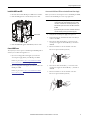
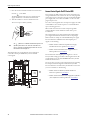
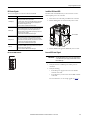
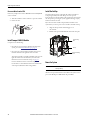
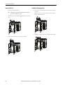
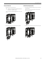
About the Controller
The following graphic shows a CompactLogix 5480 controller.
IMPORTANT
Any illustrations, charts, sample programs, and layout examples that are shown in this publication are intended solely for the purposes of example. Since
there are many variables and requirements that are associated with any particular installation, Rockwell Automation does not assume responsibility or
liability for actual use that is based upon the examples that are shown in this publication.
1
6
7
9
8
2
3
4
14
11
16
10
5
1312
15
18
20
17
19
Front View
Bottom View
22
21
23
CompactLogix 5480 Controller Parts
Number Item Description
1 DIN rail latches Secure adapter to DIN rail.
2 Mode switch Lets you choose the controller operating mode.
3 SD card slot Location for SD card.
4 Reset button Resets the controller to factory default condition.
5 Four-character display
Scrolls information about the controller, such as
firmware revision or project status.
6 USB programming port Provides temporary connection to download projects.
7 Ethernet port B1
Lets the controller connect to the following networks:
• Enterprise-level network
• Device-level network
8 Ethernet port A1
Lets the controller connect to device-level networks.
9 Ethernet port A2
10
Network and link status
indicators for ports B1,
A1, and A2
Show the state of the Ethernet ports and network
communication activity on each port.
11
Speed and link status
indicators for port X1
12 Bottom fan
Helps regulate controller temperature.
Controller ships with fans installed. You can replace
fans, if necessary.
13
Controller status
indicators
Show the state of the controller in multiple respects.
14 Top fan
Helps regulate controller temperature.
Controller ships with fans installed. You can replace
fans, if necessary.
15
MOD power and SA
power status indicators
Show the state of module (MOD) power and sensor
actuator (SA) power, respectively.
16 UPS Control RTB
Connector for control signals to and from an
uninterruptible power supply (UPS) that are used to
support a controlled shutdown upon incoming power
loss.
17
MOD power bus
connector
MOD power bus connection that passes MOD power to
the next local Compact 5000 I/O module in the system.
18 MOD power RTB
Connector for external power supply to provide MOD
power to the system.
19 SA power bus connector
SA power bus connection that passes SA power to the
next local Compact 5000 I/O module in the system.
20 SA power RTB
Connector for external power supply to provide SA
power to the system.‘
21 Ethernet port X1 Used with the COS on the controller.
22 USB 3.0 ports
Connectors for peripherals that are used with the COS
on the controller.
(2)
(2) Devices that are connected to the controller via a USB 3.0 port must reside in the same control enclosure as
the controller. This requirement applies to devices that are powered by the USB 3.0 ports or not. You must
connect the devices to a ground system that is common with the controller. Alternatively, you can connect
the device to the common ground system via a USB hub that provides galvanic isolation.
23
DisplayPort
connection
(1)
(1) Any DisplayPort cables or adapters that are used with this product must be certified by VESA. A list of
certified equipment and cables is on the VESA website (www.vesa.org). Use of non-certified cables and
adapters can cause damage or improper operation.
Connector to use a display with the COS on the
controller.

Rockwell Automation Publication 5069-IN019C-EN-P - October 2018 5
CompactLogix 5480 Controller
Required System Components
Before you install the controller, verify that you have the
following components.
System Planning
Follow these rules when planning your system configuration:
• If the CompactLogix 5480 system includes only a controller,
you can mount the DIN rail in any orientation.
• If your CompactLogix 5480 system includes local Compact
5000 I/O modules, you must mount the DIN rail horizontally.
• The controller is the left-most component in the system.
• Local Compact 5000 I/O modules are installed to the right of
the controller.
• The controller supports as many as 31 local Compact 5000
I/O modules.
• Before power-up, make sure that the end cap is installed on the
right side of the controller or rightmost local Compact 5000
I/O module, if I/O modules are used.
Components Used to Install a CompactLogix 5480 Controller
Component Description
Removable Terminal
Blocks (RTB)
An RTB that is used to connect MOD power (system-side power)
to the controller - 5069-RTB4-SCREW RTB (Ships with the
controller)
An RTB that is used to connect SA power (field-side power) -
5069-RTB6-SCREW RTB (Ships with the controller)
An RTB that is used to connect UPS (uninterruptible power) -
5069-L4UPSRTB (Ships with the controller)
External power supply for
MOD power
A power supply that is adequately sized to provide MOD power,
that is, system-side power, to the CompactLogix 5480 system.
For more information, see System Power Considerations on
page 7.
External power supply for
SA power
A power supply that is adequately sized to provide SA power, that
is, field-side power, to the CompactLogix 5480 system.
IMPORTANT: SA power is only required if your application
includes local Compact 5000 I/O modules that are connected to
devices that use SA power.
For more information, see System Power Considerations on
page 7.
External uninterruptible
power supply for UPS
control signals
A power supply that provides UPS control signals so that the
controller can save the state of the program when power is lost. A
UPS is only required if your system uses UPS control signals
For more information, see Connect Control Signals Via UPS
Control RTB on page 12.
Tools
You use the following tools to wire the RTBs:
• Screwdriver
• Wire stripper
• Wires
For more information on available wire sizes and wire insulation
stripping length, see
Specifications on page 22.
DIN rail
Compatible zinc-plated, chromate steel DIN rail.
You can use the following DIN rails:
• EN50022 - 35 x 7.5 mm (1.38 x 0.30 in.)
• EN50022 - 35 x 15 mm (1.38 x 0.60 in.)
EtherNet/IP network
components
If your CompactLogix 5480 controller operates on an EtherNet/IP
network, you must install the network and all required
components.
Software
When you install the controller, you assign IP addresses on the
controller. You can use the following to assign IP addresses:
• DHCP server
• BOOTP DHCP EtherNet/IP Commissioning tool, version 3.02.00
or later
• RSLinx® Classic software, version 4.10.00 or later
• FactoryTalk® Linx Enterprise, version 6.10.00 or later
• Logix Designer application, version 32.00.00 or later
For more information, see Set the Network Internet Protocol (IP)
Addresses on page 17.
ATTENTION: Do not discard the end cap. Use this end cap
to cover the exposed interconnections on the last module
on the DIN rail. Failure to do so could result in equipment
damage or injury from electric shock.
Components Used to Install a CompactLogix 5480 Controller
Component Description

6 Rockwell Automation Publication 5069-IN019C-EN-P - October 2018
CompactLogix 5480 Controller
Spacing
Maintain spacing from enclosure walls, wireways, and adjacent
equipment. Ambient temperature is higher at the top of an enclosed
cabinet.
The minimum distance on of a system that includes only a
CompactLogix 5480 controller is as follows:
• 25.00 mm (0.98 in.) between the sides and the cabinet
• 25.00 mm (0.98 in.) between the front of the controller and
the cabinet
• 50.00 mm (1.96 in.) between the top and bottom and
the cabinet
We recommend that you install the controller near the bottom
of the enclosure, where ambient temperature is lower.
Enclosure Selection
This example is provided to help you size an enclosure for your
CompactLogix 5480 controller. You need heat dissipation data from
all components that are planned for your enclosure to calculate the
enclosure size.
With no active method of heat dissipation, for example, air
conditioning, either of the following approximate equations can be
used for a metal cabinet.
The maximum ambient rating of the CompactLogix 5480 controller
is 60 °C (140 °F). If the maximum external cabinet temperature is
20 °C (68 °F), then T=40.
In this example, with only the controller, the heat dissipation is 72 W,
that is, the sum of all components in the enclosure. In the following
equation, T=40 and Q=72.
In this example, the enclosure must have a minimum exterior surface
of 0.386 m
2
.
If any portion of the enclosure cannot transfer heat, exclude that value
from the calculation.
The minimum installation clearance for a CompactLogix 5480
controller is 267.00 x 184.00 x 152.00 mm (10.50 x 7.25 x 6.00 in.)
HxWxD.
The standard cabinet depth in this example is 154.20 mm (6.00 in.).
To meet cooling and clearance requirements in this example, the
cabinet must be approximately 304.80 x 355.60 x 154.20 mm
(12.00 x 14.00 x 6.00 in.) HxWxD.
A = 2DW +2DH + 2WH
A = 2 x (0.1542 x 0.3556) + 2 x (0.1542 x 0.3048) +
2 x (0.3556 x 0.3048) = 0.4204 m
2
Top
Bottom
SideSide
End cap
Cabinet
Metric Imperial
Where:
• T = Temperature difference between
inside air and outside ambient (°C)
• Q = Heat that is generated in enclosure
(Watts)
• A = Enclosure surface area (m
2
)
Where:
• T = Temperature difference between
inside air and outside ambient (°F)
• Q = Heat that is generated in enclosure
(Watts)
• A = Enclosure surface area (ft
2
).
The exterior surface of all six sides of an
enclosure is calculated as:
A = 2dw + 2dh + 2wh
Where d (depth), w (width), and h (height)
are in meters.
The exterior surface of all six sides of an
enclosure is calculated as:
A = (2dw + 2dh + 2wh) /144
Where d (depth), w (width), and h (height)
are in inches.
0.38Q
1.80T - 1.10
A =
4.08Q
T - 1.10
A =
0.38(72.00)
1.80(40.00) - 1.10
A =

Rockwell Automation Publication 5069-IN019C-EN-P - October 2018 7
CompactLogix 5480 Controller
This example uses the following conditions:
• All sides of the enclosure transfer heat.
• Only the CompactLogix 5480 controller is installed.
• Ambient temperature = 20 °C (68 °F).
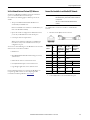
Dimensions
The controller dimensions are as follows.
Ground Considerations
You must ground DIN rails according to the Industrial Automation
Wiring and Grounding Guidelines, publication
1770-4.1
You can use the following DIN rails:
• EN50022 - 35 x 7.5 mm (1.38 x 0.30 in.)
• EN50022 - 35 x 15 mm (1.38 x 0.60 in.)
System Power Considerations
The CompactLogix 5480 controller provides power to a
CompactLogix 5480 system via RTBs that are connected to external
power supplies and installed on the controller.
The RTBs provide the following power to the system.
IMPORTANT If any of the following conditions exist, the enclosure must
be larger:
• Any sides of the enclosure cannot transfer heat.
• More equipment is included in the system.
• Ambient temperature is higher than 20 °C (68 °F)
130.21 mm
(5.13 in.)
166.20 mm
(6.54 in.)
126.54 mm
(4.98 in.)
120.02 mm
(4.73 in.)
133.66 mm
(5.26 in.)
160.00 mm
(6.30 in.)
ATTENTION: This product is grounded through the DIN rail to
chassis ground. Use zinc plated chromate-passivated steel DIN rail
to assure proper grounding. The use of other DIN rail materials (for
example, aluminum or plastic) that can corrode, oxidize, or are poor
conductors, can result in improper or intermittent grounding.
Secure DIN rail to mounting surface approximately every 200 mm
(7.8 in.) and use end-anchors appropriately. Be sure to ground the
DIN rail properly. See Industrial Automation Wiring and Grounding
Guidelines, Rockwell Automation publication
1770-4.1 for more
information.
Power Type Description
MOD Power
System-side power that is used to operate the CompactLogix 5480 system.
MOD power is provided through the MOD power RTB and passed across the
MOD power bus.
• The total continuous current draw across the MOD power bus must not be
more than 10 A, max, at 18...32V DC.
You must calculate the total MOD power that the controller and all local
Compact 5000 I/O modules draw to make sure that no more than 10 A of
MOD power is drawn.
(1)
• Confirm that the external MOD power supply is adequately sized for the
total MOD power bus current draw in the system, including the MOD
power inrush current requirements.
(1) If you connect external power to both sets of MOD power RTB terminals, however, the local Compact 5000
I/O modules can draw a maximum of 10 A in addition to the current the controller draws.
SA Power
Field-side power that is used to power field-side devices. SA power is
provided through the SA power RTB and passed across the SA power bus.
• SA power is only required if your application includes local Compact 5000
I/O modules that are connected to devices that use SA power.
• If you are using DC voltage for SA power, the total continuous current
draw across the MOD power bus must not be more than 10 A, max at
18…32V DC.
• If you are using AC voltage for SA power, the total continuous current
draw across the MOD power bus must not be more than 10 A, max at
18…240V AC.
• You can use a 5069-FPD field potential distributor to establish additional
SA power buses in a CompactLogix 5480 system.
If your system includes AC and DC modules that require SA power, you
must use a 5069-FPD field potential distributor to establish a new SA
power bus.
You separate the module types by SA power bus. For example, install DC
module on the first SA power bus in the system and install the AC
modules on the second SA power bus in the system.
• Confirm that the external SA power supply is sized adequately for the
total SA power current draw in the system.
UPS Control
Control signals from an external UPS that let the controller save the state of
the program if power is lost. The external UPS provides the power that is
required to save the program via the MOD power RTB. A UPS is not required
for controller operation

8 Rockwell Automation Publication 5069-IN019C-EN-P - October 2018
CompactLogix 5480 Controller
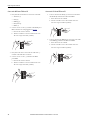
Install the Controller onto the DIN Rail
1. Confirm that the DIN rail latches are closed.
2. If the DIN rail latches are open, gently push the rear latch back
until the front latch pops up and clicks.
3. Position the controller so that the back of it faces the DIN rail.
4. Press the controller against the DIN rail until you hear a click.
5. Confirm that all latches have fully closed and the controller is
latched securely.
Connect External Power Supplies to the Controller
You must use SELV, as defined in IEC 61010-2-201, power supplies for
MOD power and SA power if there are Functional Safety modules that
are connected to the CompactLogix 5480 controller control system.
Before you connect MOD power or SA power to the RTBs on the
CompactLogix 5480 controller, complete the following tasks:
• Read
System Power Considerations on page 7.
• Confirm that the external power supplies that MOD power
and SA power are adequately sized for your
CompactLogix 5480 system. For more information, see
page 7.
• Verify that the external power supplies are turned off.
• Install the MOD power RTB, SA power RTB, and the UPS
Control RTB, if used.
IMPORTANT Remember the following:
• CompactLogix 5480 controllers do not have an embedded
power supply that powers the system.
The system is powered by external power supplies via
connections to the various power RTBs on the controller.
• We recommend that you use 1606 power supplies from
Rockwell Automation to provide MOD power, SA power,
and UPS control.
• You must use an external power supply that is dedicated
to the UPS connection.
For more information about which 1606 power supplies
are best for each power type, see the Switched Mode
Power Supply Specifications Technical Data, publication
1606-TD002.
• You can connect power from one external power supply to
the MOD power and SA power connects. However, as
stated previously, we strongly recommend that you use
separate external power supplies for MOD power and
SA power respectively.
The practice of using separate external power supplies can
help prevent unintended consequences that can result if
you use one supply.
If you use separate external power supplies, the loss of
power from one external power supply does not affect the
availability of power from the other supply. For example, if
separate external power supplies are used and SA power is
lost, MOD power remains available for the Compact 5000
I/O modules.
Electric Safety Considerations
ATTENTION: SELV, as defined in IEC 61010-2-201, power supplies
must be used for MOD and SA power if there are Functional Safety
modules that are connected to the CompactLogix 5480 control
system.
Closed PositionOpen Position

Rockwell Automation Publication 5069-IN019C-EN-P - October 2018 9
CompactLogix 5480 Controller
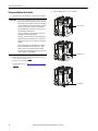
Install the MOD Power RTB
1. Hook the bottom of the MOD power RTB on the controller.
2. Push the RTB against the controller until you hear a click.
.
3. Push the RTB handle against the RTB until you hear a click.
Connect MOD Power
The way that you connect power to the MOD power RTB depends on
whether you use UPS control signals or not.
• If you are not using UPS control signals, you connect the
external power supply directly to the MOD power RTB.
In this case, proceed to
Connect to the MOD Power RTB
from a Standard External Power Supply on page 9.
• If you are using UPS control signals, you connect a UPS to the
MOD power RTB.
In this case, proceed to
Connect to the MOD Power RTB
from a UPS on page 14.
Connect to the MOD Power RTB from a Standard External Power Supply
Before you connect an external power source to the MOD power RTB,
make sure that the MOD power source is properly sized.
1. Verify that the external power supply is not powered.
2. Strip 12 mm (0.47 in.) of insulation from the wires that you
connect to the RTB.
3. Insert the wire from the 24V DC (+) connection on the
external power supply into the first MOD (+) terminal on
the RTB.
4. Turn the screwdriver to close the terminal on the wire.
The screw torque is 0.4 N•m (3.5 lb•in).
5. Insert the wire from the 24V DC (—) connection on the
external power supply into the first MOD (—) terminal on
the RTB.
6. Turn the screwdriver to close the terminal on the wire.
The screw torque is 0.4 N•m (3.5 lb•in).
MOD Power RTB
IMPORTANT Your application can require a power control device, for example,
a switch, between the external 24V DC power source and the
controller to control when the controller is powered. If so, you
must install the power control device at the VDC+ terminal on
the RTB.
If you install the power control device at the VDC- terminal, the
controller can fail to power up or power down properly.

10 Rockwell Automation Publication 5069-IN019C-EN-P - October 2018
CompactLogix 5480 Controller
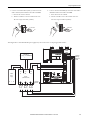
The following diagram shows an external 24V DC power supply that is
connected to the MOD power RTB when you are not using UPS
control signals.
Install the SA Power RTB
Install the SA power RTB even if you do not use SA power.
1. Hook the bottom of the SA power RTB on the controller.
2. Push the RTB against the controller until you hear a click.
3. Push the RTB handle against the RTB until you hear a click.
Connect SA DC Power
Before you connect an external DC power source to the SA power
RTB, make sure that the SA power source is properly sized.
For more information o n SA power, see
SA Power on page 7
1. Confirm that MOD power and SA power sources are
turned off.
2. Strip 12 mm (0.47 in.) of insulation from the wires that you
connect to the RTB.
3. Insert the wire from the DC (+) connection on the external
power supply into the first SA (+) terminal on the RTB.
4. Turn the screwdriver to close the terminal on the wire.
The screw torque is 0.4 N•m (3.5 lb•in).
5. Insert the wire from the DC (—) connection on the external
power supply into the first SA (—) terminal on the RTB.
6. Turn the screwdriver to close the terminal on the wire.
The screw torque is 0.4 N•m (3.5 lb•in).
24V DC
Power
Supply
+
–
SA Power RTB
IMPORTANT SA power is only required if your application includes local
Compact 5000 I/O modules that are connected to devices that
use SA power.

Rockwell Automation Publication 5069-IN019C-EN-P - October 2018 11
CompactLogix 5480 Controller
7. Insert the wire from an Earth Ground location into the first
Ground ( ) on the RTB.
The Earth Ground location can be the external SA power
supply, the DIN rail, or other Earth Ground location.
8. Turn the screwdriver to close the terminal on the wire.
The screw torque is 0.4 N•m (3.5 lb•in).
The following diagram shows an external 24V DC power supply that is
connected to the SA power RTB when you do not use UPS control
signals.
Connect SA AC Power
Before you connect an external AC power source to the SA power
RTB, make sure that the SA power source is properly sized.
For more information o n SA power, see
SA Power on page 7.
1. Verify that the SA power source is not powered on.
2. Strip 12 mm (0.47 in.) of insulation from the wires that you
connect to the RTB.
3. Insert the wire from the L1/AC (+) connection on the external
power supply into the first SA (+) terminal on the RTB.
4. Turn the screwdriver to close the terminal on the wire.
The screw torque is 0.4 N•m (3.5 lb•in).
5. Insert the wire from the L2/N/AC(—) connection on the
external power supply into the first SA(—) terminal on the
RTB.
6. Turn the screwdriver to close the terminal on the wire.
The screw torque is 0.4 N•m (3.5 lb•in).
TIP
This symbol denotes an Earth Ground terminal that provides a low
impedance path between electric circuits and earth for functional
purposes and provides noise immunity improvement. This connection
must be made for functional purposes.
24V DC
Power
Supply
+
–
24V DC
Power
Supply
+
–
MOD
Power
SA DC
Power
Earth Ground
IMPORTANT SA power is only required if your application includes local
Compact 5000 I/O modules that are connected to devices that
use SA power.

12 Rockwell Automation Publication 5069-IN019C-EN-P - October 2018
CompactLogix 5480 Controller
7. Insert the wire from an Earth Ground location into the first
Ground ( ) on the RTB.
The Earth Ground location can be the external SA power
supply, the DIN rail, or other Earth Ground location.
8. Turn the screwdriver to close the terminal on the wire.
The screw torque is 0.4 N•m (3.5 lb•in).
This diagram shows an external 240V AC power supply that is
connected to the SA power RTB when you do not use UPS
control signals.
Connect Control Signals Via UPS Control RTB
The CompactLogix 5480 controller does not have an internal energy
storage module that lets the controller save the state of the program if
system-side power is lost. You must connect an external uninterruptible
power supply (UPS) to the UPS control RTB to save the state of the
program if power is lost.
You connect control signals from an external power supply to the UPS
control RTB to let the controller experience a controlled shutdown
upon an incoming power loss.
When a UPS connection is detected, the CompactLogix 5480
controller defaults to initiate shutdown 1 minute after a power
loss indication.
We recommend that you use 1606 switched mode uninterruptible
power supplies from Rockwell Automation with a CompactLogix
5480 controller, for example, the 1606-XLS240-UPS power supply.
For more information on Bulletin 1606 uninterruptible power
supplies, see the following:
• Bulletin 1606 DC-UPS Uninterruptible Power Supply
Installation Instructions, publication
1606-IN025
• Bulletin 1606 Switched Mode Power Supplies Reference
Manual, publication
1606-RM036
The switched mode uninterruptible power supplies use a 12-volt
battery module to bridge power failures and voltage fluctuations. We
recommend that you use the 1606-XLSBATASSY1 battery module
from Rockwell Automation.
You can use other accessories, such as replacement batteries, mounting
kits, and panel/wall mounting brackets with the battery module.
For more information on and the battery module and accessories that
you can use with them, see the following:
• Bulletin 1606 12V 7Ah Battery Modules Installation
Instructions, publication
1606-IN011
• Bulletin 1606 Switched Mode Power Supply Battery Modules
(12V 7Ah) Reference Manual, publication
1606-RM037
TIP
This symbol denotes an Earth Ground terminal that provides a low
impedance path between electric circuits and earth for functional
purposes and provides noise immunity improvement. This connection
must be made for functional purposes.
24V DC
Power
Supply
+
–
240V AC
Power
Supply
+
–
MOD
Power
SA AC
Power
Earth Ground

Rockwell Automation Publication 5069-IN019C-EN-P - October 2018 13
CompactLogix 5480 Controller
UPS Control Signals
These control signals are used on the UPS Control RTB:
UPS Control RTB Terminals
Install the UPS Control RTB
Install the UPS control RTB even if you do not intend to connect
uninterruptible power to the controller.
1. Hook the bottom of the UPS power RTB on the controller.
2. Push the RTB against the controller until you hear a click.
.
3. Push the RTB handle against the RTB until you hear a click.
Connect UPS Control Signals
1. Verify that all sources of MOD power and SA power are
turned off.
2. Verify the following:
• A 24V DC power supply is connected to the 24V IN
terminals on the UPS.
• A 12V DC battery is connected to the 12V BAT terminals
on the UPS.
For more information, see the example graphic on
page 15.
Signal Description
UPS Ready (R)
An input signal from the UPS to the controller that indicates the UPS is
working and can buffer during a power failure.
The charge level for a UPS to be ready to buffer during a power failure
varies. For example, the 1606-XLS240-UPS power supply must be
greater than 85% charged to be ready.
The letter R indicates the RTB terminal for this signal.
Buffering (B)
An input signal from the UPS to the controller that indicates the UPS
battery is providing power because the external power has failed.
After a preset time (typically 1 minute after power failure), the
controller performs an orderly shutdown by stopping execution and
saving the state of the controller.
The letter B indicates the RTB terminal for this signal.
Battery Fail (F)
An input from the UPS to the controller that indicates the UPS battery
has failed, and the controller cannot operate from stored energy.
In this case, the controller does not attempt to save the state of the
program when the external power fails. The controller issues an alarm
if a UPS was previously attached and ready to buffer.
The letter F indicates the RTB terminal for this signal.
Inhibit (I)
An output signal from the controller to the UPS that disables the UPS
signal output. The INHIBIT signal is triggered after data is backed up
and the system is ready to shut down.
The letter I indicates the RTB terminal for this signal.
IMPORTANT The UPS terminal labels in this section represent the labels on
a 1606-XLS240-UPS power supply. Your UPS terminals can be
labeled differently.
UPS Control RTB

14 Rockwell Automation Publication 5069-IN019C-EN-P - October 2018
CompactLogix 5480 Controller
Connect to the MOD Power RTB from a UPS
1. Daisy chain the wires from these connections on the UPS:
• 24V OUT (+)
• Ready (1)
• Buffering (3)
• Battery Fail (5)
• Inhibit (7)
2. Connect one wire to each (+) terminal on the MOD power
RTB, as shown in the example graphic on
page 15.
a. Insert the wire into the terminal.
b. Turn the screwdriver to close the terminal on the wire.
The screw torque is 0.4 N•m (3.5 lb•in).
3. Daisy chain a wire that is connected to the 24V OUT (–)
terminal on the UPS and a second wire.
4. Connect one wire to each (–) terminal on the MOD
power RTB.
a. Insert the wire into the terminal.
b. Turn the screwdriver to close the terminal on the wire.
The screw torque is 0.4 N•m (3.5 lb•in).
Connect to the UPS Control RTB from a UPS
1. Connect a wire from the Ready (2) connection on the UPS to
the UPS Ready terminal on the UPS control RTB.
a. Insert the wire into the terminal.
b. Turn the screwdriver to close the terminal on the wire.
The screw torque is 0.4 N•m (3.5 lb•in).
2. Connect a wire from the Buffering (4) connection on the UPS
to the Buffering terminal on the UPS control RTB.
a. Insert the wire into the terminal.
b. Turn the screwdriver to close the terminal on the wire.
The screw torque is 0.4 N•m (3.5 lb•in).

Rockwell Automation Publication 5069-IN019C-EN-P - October 2018 15
CompactLogix 5480 Controller
3. Connect a wire from the Battery Fail (6) connection on the
UPS to the Battery Fail terminal on the UPS control RTB.
a. Insert the wire into the terminal.
b. Turn the screwdriver to close the terminal on the wire.
The screw torque is 0.4 N•m (3.5 lb•in).
4. Connect a wire from the Inhibit (8) connection on the UPS to
the Inhibit terminal on the UPS control RTB.
a. Insert the wire into the terminal.
b. Turn the screwdriver to close the terminal on the wire.
The screw torque is 0.4 N•m (3.5 lb•in).
This diagram shows a 1606-XLS240-UPS power supply battery that is connected to a CompactLogix 5480 controller.
UPS Ready
Buffering
Battery Fail
Inhibit
(7) Inhibit +
(8) Inhibit –
24V DC
Power
Supply
Ready
(1) (2)
+–
+– +– +–
NLPE
Buffering
(3) (4)
Battery Fail
(5) (6)
12V DC Battery
(for example, 1606-XLSBATASSY1)
+–
DC-UPS
(1606-XLS240-UPS)
24V
IN
12V
BAT
24V
OUT

16 Rockwell Automation Publication 5069-IN019C-EN-P - October 2018
CompactLogix 5480 Controller
Disconnect Wires from the RTBs
If necessary, complete these tasks to disconnect wires from any RTB
on the controller.
1. Turn the screwdriver counter-clockwise to open the terminal.
2. Remove the wire.
Install Compact 5000 I/O Modules
Complete one of the following:
• If you do not use local Compact 5000 I/O modules in the
system, proceed to
Install the End Cap on page 16.
• If you use local Compact 5000 I/O modules in the system,
install the modules to the right side of the controller.
After the I/O modules are installed, install the end cap on the
right side of the last I/O module in the system. For more
information on how to install the end cap, see
page 16.
For more information on how to install Compact 5000
I/O modules, see the installation instructions available with
each Compact 5000 I/O module catalog number.
Install the End Cap
You must install an end cap on the right side of the last module in a
CompactLogix 5480 system. The end cap covers the exposed
interconnections on the last module in the system. If you do not install
the end cap before powering the system, equipment damage or injury
from electric shock can result.
If you do not intend to install Compact 5000 I/O modules to the
system before you turn on power to the controller, install the end cap.
1. Align the end cap with the interlocking pieces on
the controller.
2. Push the end cap toward the DIN rail until it locks into place.
Power the System
After the end cap is installed on the last module in the system, turn on
power to the MOD power RTB and the SA power RTB.
IMPORTANT Make sure to remove the debris shield from the controller
before power-up.
Top Interlocking
Pieces
End Cap
Bottom Interlocking
Pieces

Rockwell Automation Publication 5069-IN019C-EN-P - October 2018 17
CompactLogix 5480 Controller
Set the Network Internet Protocol (IP) Addresses
You must set an IP address on Ethernet ports for the controller to
operate on an EtherNet/IP network via that port.
Out-of-the-box, the following applies to Ethernet ports A1, A2,
and B1:
• The ports are DHCP-enabled and the IP address is set
automatically via a DHCP server.
If there is no DHCP server available to set the IP address, you
must set the IP address manually.
• If ports A1 and A2 are configured to use DLR/Linear mode,
you set only one IP address that is used on both ports.
• Control ports must use unique subnets.
When ports A1 and A2 are configured to use DLR/Linear
mode, however, they use the same subnet because they are
configured as one port.
You can use one of the following to set the IP address on the controller
when it is in the out-of-the-box condition:
• DHCP server
• BOOTP DHCP EtherNet/IP Commissioning tool, version
3.02.00 or later
• RSLinx Classic software, version 4.10.00 or later
• FactoryTalk Linx Enterprise, version 6.10.00 or later
• Logix Designer application, version 32.00.00 or later
For more information on how to set or change the IP address on a
CompactLogix 5480 controller, see the CompactLogix 5480
Controllers User Manual, publication
5069-UM002.
Connect the Controller to an EtherNet/IP Network
Use an RJ45 cable to connect the controller to an EtherNet/IP
network.
1. If needed, wire the RJ45 connector as shown.
2. Connect RJ45 cables to the controller Ethernet ports.
IMPORTANT Before you can connect a CompactLogix 5480 controller to an
EtherNet/IP network, you must first install the network and
its components.
This section assumes that the EtherNet/IP network is
installed.
Connector
Number
Color
1585J 8-pin
Cables with
Support for 10/
100/1000 Mbps
1585J 8-pin
Cables with
Support for 10/
100 Mbps
1585J 4-pin
Cables with
Support for 10/
100 Mbps
1
White/
Orange
BI_DA+ TxData +
2 Orange BI_DA- TxData -
3
White/
Green
BI_DB+ Recv Data +
4 Blue BI_DC+ Unused —
5 White/Blue BI_DC- Unused —
6 Green BI_DB- Recv Data -
7
White/
Brown
BI_DD+ Unused —
8 Brown BI_DD- Unused —

18 Rockwell Automation Publication 5069-IN019C-EN-P - October 2018
CompactLogix 5480 Controller
Remove and Replace the Controller
1. Turn off power to the MOD power and the SA power RTBs.
2. If there are local Compact 5000 I/O modules in the system,
remove them. If not, skip to
step 3.
3. Disconnect wires from the RTBs.
For more information, see
Disconnect Wires from the RTBs
on page 16.
4. Pull the RTB handles to remove the RTBs.
IMPORTANT When you remove MOD power from the controller, you shut down
power to all modules in the CompactLogix 5480 system. That is,
all system-side is removed. When you remove SA power from the
controller, all field-side power that is provided by the controller is
removed. If SA power that is provided via a 5069-FPD field
potential distributor, the system does not lose SA power to the
right of the field potential distributor.
In this case, you must use a separate power source for the SA
power RTB on the field potential distributor.
We strongly recommend that before you remove MOD power or
SA power that you take the appropriate actions to help prevent
unintended consequences that can result from a system power
shutdown.
Despite the removal of power from SA RTBs on the controller or
field potential distributor, the 5069-OB16 and 5069-OB16F
modules continue to receive field-side power. The modules
receive power from an external power source that is connected to
the LA (+) and LA (–) module terminals.
UPS Control RTB
MOD Power RTB
SA Power RTB

Rockwell Automation Publication 5069-IN019C-EN-P - October 2018 19
CompactLogix 5480 Controller
5. Remove all cables from the controller.
6. Push down on the front of the DIN rail latches.
A click indicates that the DIN rail latches are open.
If the DIN rail latches fail to remain in the open position, hold
them down.
7. Pull the controller off the DIN rail.
8. Repeat the installation steps that are described beginning at
Install the Controller onto the DIN Rail on page 8.
9. Apply MOD power and, if necessary, SA power to the system.
Replace the Fans
The CompactLogix 5480 controller uses fans at the top and bottom of
the controller to help maintain lower operating temperatures when the
controller is operating.
Fan use includes speed control and monitoring. Faults indicate fan
operating conditions as follows:
• Minor faults - Triggered when a fan is not operating at the
requested speed or if a fan fails to operate at all.
In your Logix Designer application project, you can use the
Minor Faults tab on the Controller Properties dialog box to
monitor for these faults.
• Major fault - Triggered if both fans fail and the controller goes
over the maximum operating temperature.
In this case, the controller stops operating.
You can order replacement fans. Replacement fans come in pairs. The
fans are unique by position and keyed to help make sure that you install
the correct fan in each position.
The fans are labeled Fan 1 - Top and Fan 2 - Bottom.
Consider the following:
• We recommend that you replace the fans in pairs. That is, if
you replace the one fan, we recommend that you replace the
other fan too.
• You can replace fans during controller operation. The fans
support removal and insertion under power.
• Do not remove both fans at once if the controller is operating.
That is, remove a fan and install the replacement fan before you
remove the other fan.
TIP In your Logix Designer application project, you can
use the Major Faults tab on the Controller
Properties dialog box to monitor for this fault.
Open Position
IMPORTANT If you replace fans while the controller is operating,
do not touch live voltage components.

20 Rockwell Automation Publication 5069-IN019C-EN-P - October 2018
CompactLogix 5480 Controller
Remove the Top Fan
1. Push up on the front of the fan.
Make sure that the fan is fully disengaged before you try to pull
it out.
2. Pull the fan out of the slot at the top of the controller.
Install the Top Replacement Fan
1. Insert the top replacement fan into the slot at the top of the
controller.
Make sure the tabs at the back of the fan are inserted in the
holes at the back of the slot.
2. Push down on the top replacement fan until it clicks in place.
TIP If the hinges do not disengage when you push up on the front of the
fan, then use a screwdriver as a pry tool.
Strona się ładuje...
Strona się ładuje...
Strona się ładuje...
Strona się ładuje...
-
 1
1
-
 2
2
-
 3
3
-
 4
4
-
 5
5
-
 6
6
-
 7
7
-
 8
8
-
 9
9
-
 10
10
-
 11
11
-
 12
12
-
 13
13
-
 14
14
-
 15
15
-
 16
16
-
 17
17
-
 18
18
-
 19
19
-
 20
20
-
 21
21
-
 22
22
-
 23
23
-
 24
24


Allen-Bradley CompactLogix 5480 Installation Instructions Manual
- Typ
- Installation Instructions Manual
- Niniejsza instrukcja jest również odpowiednia dla
w innych językach
- English: Allen-Bradley CompactLogix 5480