Indesit K3G76S(X)/U instrukcja
- Kategoria
- Mikrofale
- Typ
- instrukcja
Ten podręcznik jest również odpowiedni dla

GB
COOKER AND OVEN
K3G76/U
K3G76S/U
K3T76/U
K3T76S/U
Contents
Installation, 2-5
Positioning and levelling
Electrical connection
Gas connection
Adapting to different types of gas
Table of burner and nozzle specifications
Table of characteristics
Description of the appliance, 6
Overall view
Control panel
Start-up and use, 7-11
Using the hob
Using the oven
Cooking modes
Practical cooking advice
Electronic timer
Planning cooking with the electronic programmer
Oven cooking advice table
Precautions and tips, 12
General safety
Disposal
Respecting and conserving the environment
Care and maintenance, 13
Switching the appliance off
Cleaning the appliance
Replacing the oven light bulb
Gas tap maintenance
Assistance
Operating Instructions
English, 1
GB
Polski, 14
PL
Magyar, 27
HU

2
GB
! Before operating your new appliance please read this
instruction booklet carefully. It contains important
information concerning the safe installation and
operation of the appliance.
! Please keep these operating instructions for future
reference. Make sure that the instructions are kept with
the appliance if it is sold, given away or moved.
! The appliance must be installed by a qualified
professional according to the instructions provided.
! Any necessary adjustment or maintenance must be
performed after the cooker has been disconnected
from the electricity supply.
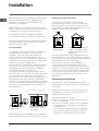
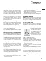
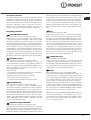
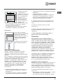
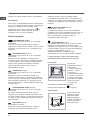
Room ventilation
The appliance may only be installed in permanently-
ventilated rooms, according to current national
legislation. The room in which the appliance is
installed must be ventilated adequately so as to
provide as much air as is needed by the normal gas
combustion process (the flow of air must not be lower
than 2 m
3
/h per kW of installed power).
The air inlets, protected by grilles, should have a duct
with an inner cross section of at least 100 cm
2
and
should be positioned so that they are not liable to
even partial obstruction (
see figure A
).
These inlets should be enlarged by 100% - with a
minimum of 200 cm
2
- whenever the surface of the hob
is not equipped with a flame failure safety device.
When the flow of air is provided in an indirect manner
from adjacent rooms (
see figure B
), provided that
these are not communal parts of a building, areas with
increased fire hazards or bedrooms, the inlets should
be fitted with a ventilation duct leading outside as
described above.
! After prolonged use of the appliance, it is advisable to
open a window or increase the speed of any fans used.
Disposing of combustion fumes
The disposal of combustion fumes should be
guaranteed using a hood connected to a safe and
efficient natural suction chimney, or using an electric
fan that begins to operate automatically every time the
appliance is switched on (
see figure
).
! The liquefied petroleum gases are heavier than air
and collect by the floor, therefore all rooms containing
LPG cylinders must have openings leading outside so
that any leaked gas can escape easily.
LPG cylinders, therefore, whether partially or
completely full, must not be installed or stored in
rooms or storage areas that are below ground level
(cellars, etc.). Only the cylinder being used should be
stored in the room; this should also be kept well away
from sources of heat (ovens, chimneys, stoves) that
may cause the temperature of the cylinder to rise
above 50°C.
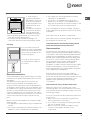
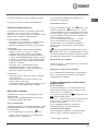
Positioning and levelling
! It is possible to install the appliance alongside
cupboards whose height does not exceed that of the
hob surface.
! Make sure that the wall in contact with the back of
the appliance is made from a non-flammable, heat-
resistant material (T 90°C).
To install the appliance correctly:
• Place it in the kitchen, dining room or the bed-sit
(not in the bathroom).
• If the top of the hob is higher than the cupboards,
the appliance must be installed at least 200 mm
away from them.
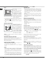
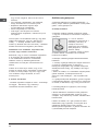
• If the cooker is installed underneath a wall cabinet,
there must be a minimum distance of 420 mm
between this cabinet and the top of the hob.
Installation
Adjacent room Room requiring
ventilation
A
B
Ventilation opening for
comburent air
Increase in the gap
between the door and
the flooring
A
Fumes channelled
straight outside
Fumes channelled through a
chimney or a branched flue
system (reserved for cooking
appliances)

GB
3
• If the cooker is
installed underneath a
wall cabinet, there must
be a minimum distance
of 420 mm between this
cabinet and the top of
the hob.
This distance should be
increased to 700 mm if
the wall cabinets are
flammable (
see figure
).
• Do not position blinds behind the cooker or less
than 200 mm away from its sides.
• Any hoods must be installed according to the
instructions listed in the relevant operating manual.
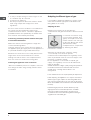
Levelling
If it is necessary to level the
appliance, screw the adjustable
feet into the places provided on
each corner of the base of the
cooker (
see figure
).
The legs* fit into the slots on
the underside of the base of
the cooker.
Electrical connection
Install a standardised plug corresponding to the load
indicated on the appliance data plate (
see Technical
data table
).
The appliance must be directly connected to the
mains using an omnipolar circuit-breaker with a
minimum contact opening of 3 mm installed between
the appliance and the mains. The circuit-breaker must
be suitable for the charge indicated and must comply
with NFC 15-100 regulations (the earthing wire must
not be interrupted by the circuit-breaker). The supply
cable must be positioned so that it does not come into
contact with temperatures higher than 50°C at any
point.
Before connecting the appliance to the power supply,
make sure that:
• The appliance is earthed and the plug is compliant with
the law.
• The socket can withstand the maximum power of the
appliance, which is indicated by the data plate.
HOOD
420
Min.
min. 650 mm. with hood
min.
700 mm. without hood
mm.
600
Min. mm.
420
Min. mm.
• The voltage is in the range between the values
indicated on the data plate.
• The socket is compatible with the plug of the
appliance. If the socket is incompatible with the
plug, ask an authorised technician to replace it. Do
not use extension cords or multiple sockets.
! Once the appliance has been installed, the power
supply cable and the electrical socket must be easily
accessible.
! The cable must not be bent or compressed.
! The cable must be checked regularly and replaced
by authorised technicians only.
! The manufacturer declines any liability should
these safety measures not be observed.
Gas connection
Connection to the gas network or to the gas cylinder
may be carried out using a flexible rubber or steel hose,
in accordance with current national legislation and after
making sure that the appliance is suited to the type of
gas with which it will be supplied (see the rating sticker
on the cover: if this is not the case
see below
). When
using liquid gas from a cylinder, install a pressure
regulator which complies with current national
regulations. To make connection easier, the gas supply
may be turned sideways*: reverse the position of the
hose holder with that of the cap and replace the gasket
that is supplied with the appliance.
! Check that the pressure of the gas supply is
consistent with the values indicated in the Table of
burner and nozzle specifications (
see below
). This will
ensure the safe operation and durability of your
appliance while maintaining efficient energy
consumption.
Gas connection using a flexible rubber hose
Make sure that the hose complies with current
national legislation. The internal diameter of the hose
must measure: 8 mm for liquid gas supply; 13 mm for
methane gas supply.
Once the connection has been performed, make sure
that the hose:
• Does not come into contact with any parts that
reach temperatures of over 50°C.
• Is not subject to any pulling or twisting forces and
that it is not kinked or bent.
• Does not come into contact with blades, sharp
corners or moving parts and that it is not
compressed.

4
GB
• Is easy to inspect along its whole length so that
its condition may be checked.
• Is shorter than 1500 mm.
• Fits firmly into place at both ends, where it will be
fixed using clamps that comply with current
regulations.
! If one or more of these conditions is not fulfilled or if
the cooker must be installed according to the
conditions listed for class 2 - subclass 1 appliances
(installed between two cupboards), the flexible steel
hose must be used instead (
see below
).
Connecting a flexible jointless stainless steel pipe
to a threaded attachment
Make sure that the hose and gaskets comply with
current national legislation.
To begin using the hose, remove the hose holder on
the appliance (the gas supply inlet on the appliance is
a cylindrical threaded 1/2 gas male attachment).
! Perform the connection in such a way that the hose
length does not exceed a maximum of 2 metres,
making sure that the hose is not compressed and
does not come into contact with moving parts.
Checking the tightness of the connection
When the installation process is complete, check the
hose fittings for leaks using a soapy solution. Never
use a flame.
Adapting to different types of gas
It is possible to adapt the appliance to a type of gas
other than the default type (this is indicated on the
rating label on the cover).
Adapting the hob
Replacing the nozzles for the hob burners:
1. Remove the hob grids and slide the burners off their
seats.
2. Unscrew the nozzles using
a 7 mm socket spanner (
see
figure
), and replace them with
nozzles suited to the new type
of gas (
see Burner and nozzle
specifications table
).
3. Replace all the components
by following the above
instructions in reverse.
Adjusting the hob burners’ minimum setting:
1. Turn the tap to the minimum position.
2. Remove the knob and adjust the regulatory screw,
which is positioned inside or next to the tap pin, until
the flame is small but steady.
! If the appliance is connected to a liquid gas
supply, the regulatory screw must be fastened as
tightly as possible.
3. While the burner is alight, quickly change the position of
the knob from minimum to maximum and vice versa
several times, checking that the flame is not
extinguished.
! The hob burners do not require primary air adjustment.
! After adjusting the appliance so it may be used with a
different type of gas, replace the old rating label with a
new one that corresponds to the new type of gas (these
labels are available from Authorised Technical Assistance
Centres).
! Should the gas pressure used be different (or vary
slightly) from the recommended pressure, a suitable
pressure regulator must be fitted to the inlet hose in
accordance with current national regulations relating to
“regulators for channelled gas”.

GB
5
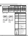
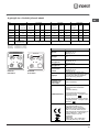
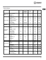
Table of burner and nozzle specifications
Table 1 G30 (GPB-B) G20 (GZ50) G2.350 (GZ35)
S
S
R
A
S
S
TC
A
K3G76/U K3T76/U
K3G76S/U K3T76S/U
TABLE OF CHARACTERISTSICS
Dimensions (with
drawn guide rails)
width 39 cm
height 34 cm
depth 41 cm
Volume (with
drawn guide rails)
54 l
Dimensions (with
wire guide rails)
width 38 cm
height 34 cm
depth 41 cm
Volume (with wire
guide rails)
53 l
Useful
measurements
relating to the oven
compartment
width 42 cm
height 23 cm
depth 44 cm
Burners
may be adapted for use with any type
of gas shown on the data plate, which
is located inside the flap or, after the
oven compartment has been opened,
on the left-hand wall inside the oven.
Voltage and
frequency
see data plate
ENERGY LABEL
Directive 2002/40/EC on the label of
electric ovens.
Standard EN 50304
Energy consumption for Natural
convection – heating mode:
Convection;
Declared energy consumption for
Forced convection Class – heating
mode: Baking
This appliance conforms to the
following European Economic
Community directives: 2006/95/EC
dated 12/12/06 (Low Voltage) and
subsequent amendments -
2004/108/EC dated 15/12/04
(Electromagnetic Compatibility) and
subsequent amendments - 93/68/EEC
dated 22/07/93 and subsequent
amendments.
2002/96/EC
2009/142 of 30/11/09 (Gas)
1275/2008 (Stand-by/ Off mode)

6
GB
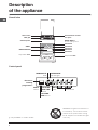
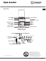
Description
of the appliance
Overall view
Control panel
*
Only available in certain models.
BURNER
control knobs
SELECTOR
knob
THERMOSTAT
indicator light
THERMOSTAT
knob
Electronic
cooking
programmer*
TIMER
button
COOKING
END TIME
button
COOKING
TIME button
Hob grid
Control panel
GRILL
DRIPPING PAN
GUIDE RAILS
for the sliding racks
position 3
position 2
position 1
Gas burner
Containment surface
for spills
Adjustable foot
Adjustable foot
position 5
position 4
WARNING! The glass lid can break in if
it is heated up. Turn off all the burners
and the electric plates before closing
the lid. *Applies to the models with glass
cover only.

GB
7
Start-up and use
Using the hob
Lighting the burners
For each BURNER knob there is a full ring showing
the strength of the flame for the relevant burner.
To light one of the burners on the hob:
1. Bring a flame or gas lighter close to the burner.
2. Press the BURNER knob and turn it in an
anticlockwise direction so that it is pointing to the
maximum flame setting E.
3. Adjust the intensity of the flame to the desired
level by turning the BURNER knob in an
anticlockwise direction. This may be the minimum
setting C, the maximum setting E or any position in
between the two.
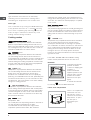
If the appliance is fitted with
an electronic lighting device*
(
see figure
), press the
BURNER knob and turn it in
an anticlockwise direction,
towards the minimum flame
setting, until the burner is lit.
The burner may be
extinguished when the knob is released. If this
occurs, repeat the operation, holding the knob down
for a longer period of time.
! If the flame is accidentally extinguished, switch off
the burner and wait for at least 1 minute before
attempting to relight it.
If the appliance is equipped with a flame failure
safety device*, press and hold the BURNER knob
for approximately 2-3 seconds to keep the flame
alight and to activate the device.
To switch the burner off, turn the knob until it
reaches the stop position •.
Practical advice on using the burners
For the burners to work in the most efficient way
possible and to save on the amount of gas
consumed, it is recommended that only pans that
have a lid and a flat base are used. They should
also be suited to the size of the burner:
Burner ø Cookware Diameter (cm)
Fast(R) 24-26
SemiFast(S) 16-20
Auxiliary(A) 10-14
TripleCrown(TC) 24-26
To identify the type of burner, please refer to the
diagrams contained in the “Burner and nozzle
specifications”.
Using the oven
! The first time you use your appliance, heat the
empty oven with its door closed at its maximum
temperature for at least half an hour. Ensure that the
room is well ventilated before switching the oven off
and opening the oven door. The appliance may emit
a slightly unpleasant odour caused by protective
substances used during the manufacturing process
burning away.
! Before operating the product, remove all plastic
film from the sides of the appliance.
! Never put objects directly on the bottom of the
oven; this will avoid the enamel coating being
damaged.
! Should the appliance be equipped with an
electronic programmer*, to use the electric oven, just
press buttons
and at the same time (the
symbol will appear on the display) before
selecting the desired cooking function.
1. Select the desired cooking mode by turning the
SELECTOR knob.
2. Select the recommended temperature for the
cooking mode or the desired temperature by turning
the THERMOSTAT knob.
A list detailing cooking modes and suggested
cooking temperatures can be found in the relevant
table (
see Oven cooking advice table
).
During cooking it is always possible to:
• Change the cooking mode by turning the
SELECTOR knob.
• Change the temperature by turning the
THERMOSTAT knob.
• Stop cooking by turning the SELECTOR knob to
the “0” position.
! Always place cookware on the rack(s) provided.
THERMOSTAT indicator light
When this is illuminated, the oven is generating
heat. It switches off when the inside of the oven
reaches the selected temperature. At this point the
*
Only available in certain models.

8
GB
entrecôte). This cooking mode uses a limited amount of
energy and is ideal for grilling Place the food in the centre
of the rack, as it will not be cooked properly if it is placed
in the corners.
DOUBLE GRILLDOUBLE GRILL
DOUBLE GRILLDOUBLE GRILL
DOUBLE GRILL
mode
Temperature: Max.
This provides a larger grill than the normal grill setting and
has an innovative design that improves cooking efficiency
by 50% and eliminates the cooler corner areas. Use this
grilling mode to achieve a uniform browning on top of the
food.
GRATIN
mode
Temperature: any temperature between 50°C and 200°C.
The top heating element and the rotisserie (where
present) are activated and the fan begins to operate.
This combination of features increases the effectiveness
of the unidirectional thermal radiation provided by the
heating elements through forced circulation of the air
throughout the oven. This helps prevent food from
burning on the surface and allows the heat to penetrate
right into the food.
! The GRILL, DOUBLE GRILL and GRATIN cooking
modes must be performed with the oven door shut.
Rotisserie*
To operate the rotisserie
proceed as follows:
1. Place the dripping pan
in position 1.
2. Place the rotisserie
support in position 4 and
insert the spit in the hole
provided on the back
panel of the oven (
see
figure
).
3. Activate the rotisserie
by selecting
with the SELECTOR knob.
Lower oven compartment
There is a compartment
underneath the oven
that may be used to
storeoven accessories or
deep dishes. To open
the door pull it
downwards (
see
figure
).
light illuminates and switches off alternately,
indicating that the thermostat is working and is
maintaining the temperature at a constant level.
Oven light
This is switched on by turning the SELECTOR knob
to any position other than “0”. It remains lit as long
as the oven is operating. By selecting
88
88
8 with the
knob, the light is switched on without any of the
heating elements being activated.
Cooking modes
CONVECTION OVENCONVECTION OVEN
CONVECTION OVENCONVECTION OVEN
CONVECTION OVEN
mode
Temperature: any temperature between 50°C and Max.
Both the top and bottom heating elements will come on.
When using this traditional cooking mode, it is best to use
one cooking rack only. If more than one rack is used, the
heat will be distributed in an uneven manner.
BAKING BAKING
BAKING BAKING
BAKING mode
Temperature: any temperature between 50°C and Max.
The rear heating element and the fan are switched on,
thus guaranteeing the distribution of heat in a delicate and
uniform manner throughout the entire oven. This mode is
ideal for baking and cooking temperature sensitive foods
(such as cakes that need to rise) and for the preparation
of pastries on 3 shelves simultaneously.
PIZZA mode
Temperature: any temperature between 50°C and Max.
The circular heating elements and the elements at the
bottom of the oven are switched on and the fan is
activated. This combination heats the oven rapidly by
producing a considerable amount of heat, particularly from
the element at the bottom. If you use more than one rack
simultaneously, switch the position of the dishes halfway
through the cooking process.
MULTI-COOKING mode
Temperature: any temperature between 50°C and Max.
All the heating elements (top, bottom and circular) switch
on and the fan begins to operate. Since the heat remains
constant throughout the oven, the air cooks and browns
food in a uniform manner. A maximum of two racks may
be used at the same time.
GRILL GRILL
GRILL GRILL
GRILL mode
Temperature: Max.
The central part of the top heating element is switched on.
The high and direct temperature of the grill is
recommended for food that requires a high surface
temperature (veal and beef steaks, fillet steak and

GB
9
*
Only available in certain models.
Any necessary modifications can be made by
repeating the above process.
Timer feature
This function may be accessed by pressing the
nn
nn
n
button, after which the display will show the symbol
nn
nn
n. Every time the + button is pressed it
corresponds to a time increase of 10 seconds, until
it reaches 99 minutes and 50 seconds. After this
point, each press of the button represents an
increase of one minute, up to a maximum of 10 hours.
Pressing the - button reduces the time.
After the time period has been set, the timer will
begin to count down. When the timer reaches zero,
the buzzer will sound (this may be stopped by
pressing any button).
The time may be displayed by pressing the
vv
vv
v
button, and the
nn
nn
n symbol indicates that the timer
function has been set. After approximately 7 seconds,
the display will automatically revert to the timer.
Cancelling a time that has already been set
Press the - button until the display shows
0:00.0:00.
0:00.0:00.
0:00.
Adjusting the buzzer volume
After selecting and confirming the clock settings,
use the - button to adjust the volume of the alarm
buzzer.
Planning cooking with the electronic
programmer*
Setting the clock
After the appliance has been connected to the
power supply, or after a blackout, the display will
automatically reset to 0:00 and begin to blink. To set
the time:
1. Press the COOKING TIME button
and the
COOKING END TIME
simultaneously.
2. Within 4 seconds of having pressed these
buttons, set the exact time by pressing the + and -
buttons. The + button advances the hours and the
-
button decreases the hours.
Once the time has been set, the programmer
automatically switches to manual mode.
Setting the timer
The timer enables a countdown to be set, when the
! Do not place flammable materials in the lower oven
compartment.
! The internal surfaces of the compartment (where
present) may become hot.
Practical cooking advice
! Do not place racks in position 1 or 5 during fan-assisted
cooking. Excessive direct heat can burn temperature
sensitive foods.
MULTI-COOKING
• Use positions 2 and 4, placing the food that requires
more heat on the rack in position 2.
• Place the dripping pan on the bottom and the rack on top.
GRILL
• When using the GRILL and DOUBLE GRILL cooking
modes, place the rack in position 5 and the dripping
pan in position 1 to collect cooking residues (fat and/or
grease). When using the GRATIN cooking mode, place
the rack in position 2 or 3 and the dripping pan in
position 1 to collect cooking residues.
• We recommend that the power level is set to maximum.
The top heating element is regulated by a thermostat
and may not always operate contantly.
PIZZA OVEN MODE
• Use a light aluminium pizza pan. Place it on the rack
provided.
For a crispy crust, do not use the dripping pan as it
prevents the crust from forming by extending the total
cooking time.
• If the pizza has a lot of toppings, we recommend
adding the mozzarella cheese on top of the pizza
halfway through the cooking process.
Electronic timer*
This function displays the time and works as a timer
which counts down to zero.
! All functions will be implemented approximately 7
seconds after they have been set.
Resetting the clock
After the appliance has been connected to the power
supply, or after a power cut, the clock display will
begin to blink, showing the figure:
0:000:00
0:000:00
0:00
• Press button
vv
vv
v and then buttons - and + to set
the exact time. Press and hold the buttons to
quicken the count upwards.

10
GB
*
Only available in certain models.
P
At this point, the oven is programmed to switch on
automatically at 12:30 and switch off after 30
minutes, at 13.00.
Setting the cooking time with an immediate start
Follow the above procedure for setting the cooking
time (points 1-3).
! When the letter A appears, this indicates that both
the cooking time and the end cooking time have
been programmed in AUTO mode. To restore the
oven to manual operation, after each AUTO cooking
mode press the COOKING TIME
and END
COOKING TIME
buttons simultaneously.
! The symbol
mm
mm
m
will remain lit, along with the oven,
for the entire duration of the cooking programme.
The set cooking duration can be displayed at any
time by pressing the COOKING TIME button
,
and the cooking end time may be displayed by
pressing the END COOKING TIME button
.
When the cooking time has elapsed a buzzer
sounds. To stop it, press any button apart from the
+ and - buttons.
Cancelling a previously set cooking programme
Press the COOKING TIME button
and the
COOKING END TIME
simultaneously.
Correcting or cancelling previously set data
The data entered can be changed at any time by
pressing the corresponding button (TIMER,
COOKING TIME or COOKING END TIME) and the +
or - button.
When the cooking time data is cancelled, the
cooking end time data is also cancelled
automatically, and vice versa.
If the oven has already been programmed, it will not
accept cooking end times which are before the start
of the programmed cooking process.
time has elapsed a buzzer sounds.
To set the timer proceed as follows:
1. press the TIMER button
. The display shows:
N.
2. Press the + and - buttons to set the desired time.
3. When the buttons are released the timer begins
counting down and the current time appears on the
display.
R
4. After the time has elapsed a buzzer will sound,
and this can be switched off by pressing any button
(except the + and - buttons). The symbol
will
switch off.
!!
!!
!
The timer does not switch the oven on or off.
Adjusting the volume of the buzzer
After selecting and confirming the clock settings,
use the - button to adjust the volume of the alarm
buzzer.
Setting the cooking time with a delayed start
First decide which cooking mode you wish to use
and set a suitable temperature using the SELECTOR
and THERMOSTAT knobs on the oven.
At this point it is possible to set the cooking time:
1. Press the COOKING TIME button
.
2. Within 4 seconds of having pressed this button,
set the desired amount of time by pressing the + and
- buttons. If, for example, you wish to set a cooking
time of 30 minutes, the display will show:
N
3. 4 seconds after the buttons are released, the
current time (for example 10.00) reappears on the
display with the symbol
mm
mm
m
and the letter A (AUTO).
Next the desired cooking end time must be set:
4. Press the END COOKING TIME button
.
5. Within 4 seconds of having pressed this button,
adjust the cooking end time by pressing the + and -
buttons. If, for example, you want cooking to end at
13.00, the display shows:
O
6. 4 seconds after the buttons are released, the
current time (for example 10.00) reappears on the
display with the letter A (AUTO).

GB
11
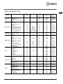
Oven cooking advice table
Cooking
modes
Foods Weight
(in kg)
Rack position Preheating
time
(min)
Recommended
temperature
Cooking
time
(minutes)
Convection
Oven
Duck
Roast veal or beef
Roast pork
Biscuits (shortcrust pastry)
Tarts
1
1
1
-
1
3
3
3
3
3
15
15
15
15
15
200
200
200
180
180
65-75
70-75
70-80
15-20
30-35
Baking mode
Tarts
Fruit cakes
Sponge cake made with
yoghurt
Sponge cake
Stuffed pancakes (on 2 racks)
Small cakes (on 2 racks)
Cheese puffs (on 2 racks)
Cream puffs (on 3 racks)
Biscuits (on 3 racks)
Meringues (on 3 racks)
0.5
1
0.7
0.5
1.2
0.6
0.4
0.7
0.7
0.5
3
2 or 3
3
3
2 and 4
2 and 4
2 and 4
1 and 3 and 5
1 and 3 and 5
1 and 3 and 5
15
15
15
15
15
15
15
15
15
15
180
180
180
160
200
190
210
180
180
90
20-30
40-45
40-50
25-30
30-35
20-25
15-20
20-25
20-25
180
Pizza Mode
Pizza
Roast veal or beef
Chicken
0.5
1
1
3
2
2 or 3
15
10
10
220
220
180
15-20
25-30
60-70
Multi-cooking
Pizza (on 2 racks)
Lasagne
Lamb
Roast chicken + potatoes
Mackerel
Sponge cake made with
yoghurt
Cream puffs (on 2 racks)
Biscuits (on 2 racks)
Sponge cake (on 1 rack)
Sponge cake (on 2 racks)
Savoury pies
1
1
1
1+1
1
1
0.5
0.5
0.5
1
1.5
2 and 4
3
2
2 and 4
2
2
2 and 4
2 and 4
2
2 and 4
3
15
10
10
15
10
10
10
10
10
10
15
230
180
180
200
180
170
190
180
170
170
200
15-20
30-35
40-45
60-70
30-35
40-50
20-25
10-15
15-20
20-25
25-30
Grill
Sole and cuttlefish
Squid and prawn kebabs
Cuttlefish
Cod fillet
Grilled vegetables
Veal steak
Sausages
Hamburgers
Mackerel
Toasted sandwiches (or toast)
0.7
0.6
0.6
0.8
0.4
0.8
0.6
0.6
1
n.° 4 and 6
4
4
4
4
3 or 4
4
4
4
4
4
100%
100%
100%
100%
100%
100%
100%
100%
100%
100%
10-12
8-10
10-15
10-15
15-20
15-20
15-20
10-12
15-20
3-5
Veal steak
Cutlets
Hamburgers
Mackerel
Toast
1
1
1
1
n.° 4
4
4
4
4
4
5
5
5
5
5
Max
Max
Max
Max
Max
15-20
15-20
7-10
15-20
2-3
Double Grill
With the rotisserie
Spit-roast veal
Spit-roast chicken
1.0
2.0
5
5
Max
Max
70-80
70-80
Grilled chicken
Cuttlefish
1.5
1.5
2
2
10
10
200
200
55-60
30-35
With the rotisserie
Spit-roast veal
Spit-roast chicken
Spit-roast lamb
1.5
1.5
1.5
5
5
5
200
200
200
70-80
70-80
70-80
Gratin
With multi-spit rotisserie
(selected models only)
Meat kebabs
Vegetable kebabs
1.0
0.8
5
5
Max
Max
40-45
25-30

12
GB
Precautions and tips
! This appliance has been designed and manufactured in
compliance with international safety standards.
The following warnings are provided for safety reasons
and must be read carefully.
General safety
• The appliance was designed for domestic use
inside the home and is not intended for
commercial or industrial use.
• The appliance must not be installed outdoors,
even in covered areas. It is extremely dangerous
to leave the appliance exposed to rain and
storms.
• Do not touch the appliance with bare feet or with
wet or damp hands and feet.
• The appliance must be used by adults only for the
preparation of food, in accordance with the
instructions outlined in this booklet. Any other use
of the appliance (e.g. for heating the room)
constitutes improper use and is dangerous. The
manufacturer may not be held liable for any
damage resulting from improper, incorrect and
unreasonable use of the appliance.
• The instruction booklet accompanies a class 1
(insulated) or class 2 - subclass 1 (recessed
between 2 cupboards) appliance.
• Keep children away from the oven.
• Make sure that the power supply cables of other
electrical appliances do not come into contact
with the hot parts of the oven.
• The openings used for the ventilation and
dispersion of heat must never be covered.
• Always use oven gloves when placing cookware
in the oven or when removing it.
• Do not use flammable liquids (alcohol, petrol,
etc...) near the appliance while it is in use.
• Do not place flammable material in the lower
storage compartment or in the oven itself. If the
appliance is switched on accidentally, it could
catch fire.
• Always make sure the knobs are in the “•”
position when the appliance is not in use.
• When unplugging the appliance, always pull the
plug from the mains socket; do not pull on the
cable.• Never perform any cleaning or
maintenance work without having disconnected
the appliance from the electricity mains.
• If the appliance breaks down, under no
circumstances should you attempt to repair the
appliance yourself. Repairs carried out by
inexperienced persons may cause injury or further
malfunctioning of the appliance. Contact
Assistance.
• Do not rest heavy objects on the open oven door.
• The appliance should not be operated by people
(including children) with reduced physical,
sensory or mental capacities, by inexperienced
individuals or by anyone who is not familiar with
the product. These individuals should, at the very
least, be supervised by someone who assumes
responsibility for their safety or receive
preliminary instructions relating to the operation of
the appliance.
• Do not let children play with the appliance.
Disposal
• When disposing of packaging material: observe local
legislation so that the packaging may be reused.
• The European Directive 2002/96/EC relating to Waste
Electrical and Electronic Equipment (WEEE) states that
household appliances should not be disposed of using
the normal solid urban waste cycle. Exhausted
appliances should be collected separately in order to
optimise the cost of re-using and recycling the
materials inside the machine, while preventing potential
damage to the atmosphere and to public health. The
crossed-out dustbin is marked on all products to
remind the owner of their obligations regarding
separated waste collection. For more information
relating to the correct disposal of household
appliances, owners should contact their local
authorities or appliance dealer.
Respecting and conserving the environment
• You can help to reduce the peak load of the electricity
supply network companies by using the oven in the
hours between late afternoon and the early hours of the
morning.
• Always keep the oven door closed when using the
GRILL, DOUBLE GRILL and GRATIN modes: this will
achieve better results while saving energy
(approximately 10%).
• Check the door seals regularly and wipe them clean to
ensure they are free of debris so that they adhere
properly to the door, thus avoiding heat dispersion.

GB
13
Switching the appliance off
Disconnect your appliance from the electricity
supply before carrying out any work on it.
Cleaning the appliance
! Never use steam cleaners or pressure cleaners on
the appliance.
• The stainless steel or enamel-coated external
parts and the rubber seals may be cleaned using
a sponge that has been soaked in lukewarm water
and neutral soap. Use specialised products for
the removal of stubborn stains. After cleaning,
rinse well and dry thoroughly. Do not use abrasive
powders or corrosive substances.
• The hob grids, burner caps, flame spreader rings
and burners may be removed to make cleaning
easier; wash them in hot water and non-abrasive
detergent, making sure all burnt-on residue is
removed before drying them thoroughly.
• For hobs with electronic ignition, the terminal part
of the electronic lighting devices should be
cleaned frequently and the gas outlet holes
should be checked for blockages.
• The inside of the oven should ideally be cleaned
after each use, while it is still lukewarm. Use hot
water and detergent, then rinse well and dry with
a soft cloth. Do not use abrasive products.
•
Clean the glass part of the oven door using a
sponge and a non-abrasive cleaning product,
then dry thoroughly with a soft cloth. Do not use
rough abrasive material or sharp metal scrapers
as these could scratch the surface and cause the
glass to crack.
• The accessories can be washed like everyday
crockery, and are even dishwasher safe.
The cover*
If the cooker is fitted with
a glass cover, this cover
should be cleaned using
lukewarm water. Do not
use abrasive products.
It is possible to remove
the cover in order to
make cleaning the area
behind the hob easier.
Open the cover fully and pull it upwards (
see figure
).
! Do not close the cover when the burners are alight
or when they are still hot.
! Remove any liquid from the lid before opening it.
Inspecting the oven seals
Check the door seals around the oven regularly. If
the seals are damaged, please contact your nearest
Authorised After-sales Service Centre. We
recommend that the oven is not used until the seals
have been replaced.
Replacing the oven light bulb
1. After disconnecting the oven
from the electricity mains, remove
the glass lid covering the lamp
socket (
see figure
).
2. Remove the light bulb and
replace it with a similar one:
voltage 230 V, wattage 25 W, cap
E 14.
3. Replace the lid and reconnect the oven to the
electricity supply.
Gas tap maintenance
Over time, the taps may become jammed or difficult to
turn. If this occurs, the tap must be replaced.
! This procedure must be performed by a qualified
technician who has been authorised by the
manufacturer.
Assistance
Please have the following information to hand:
• The appliance model (Mod.).
• The serial number (S/N).
This information can be found on the data plate
located on the appliance and/or on the packaging.
Care and maintenance
*
Only available in certain models.

PL
14
Instrukcja obs∏ugi
Instalacja 15-18
Ustawienie
Pod∏àczenie do instalacji elektrycznej
Pod∏àczenie gazu do kuchni
Dostosowanie kuchni do innych rodzajów gazów
Dane techniczne
Parametry dysz i palników
Opis kuchni 19
Ogólny widok
Panel kontrolny
Uruchomienie i obs∏uga kuchni 20-24
Obs∏uga p∏yty gazowej
Obs∏uga piekarnika
Programy pieczenia
Wskazówki dotyczàce pieczenia
Elektroniczny programator
Programowanie pieczenia
Pieczenie w piekarniku – porady praktyczne
Ârodki ostro˝noÊci i porady 25
Ogólne informacje o bezpieczeƒstwie
Pozbywanie si´ starych urzàdzeƒ elektrycznych
Oszcz´dnoÊç energii i ochrona Êrodowiska
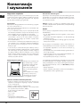
Konserwacja i czyszczenie 26
Wy∏àczenie urzàdzenia
Czyszczenie
Wymiana ˝arówki
Smarowanie zaworów gazu
Serwis
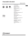
Kuchnia z piekarnikiem
K3G76/U
K3G76S/U
K3T76/U
K3T76S/U
English, 1
PL
Polski, 14
GB
Magyar, 27
HU

Instalacja
! Przed przystàpieniem do u˝ytkowania urzàdzenia, nale˝y
starannie zapoznaç si´ z podr´cznikiem u˝ytkownika. Za-
wiera on wa˝ne zalecenia dotyczàce bezpieczeƒstwa insta-
lacji, obs∏ugi oraz konserwacji kuchenki. Podr´cznik nale˝y
zachowaç do póêniejszego u˝ytku.
! Instrukcj´ nale˝y zachowaç na przysz∏oÊç. Instrukcja mu-
si byç do∏àczona do urzàdzenia w przypadku sprzeda˝y,
przekazywania innym osobom lub przeprowadzki.
! Poni˝sze instrukcje przeznaczone sà dla wykwalifikowane-
go specjalisty instalujàcego urzàdzenie. Instrukcje te majà
na celu zapewnienie mo˝liwie najbardziej profesjonalnego
i doÊwiadczonego wykonania czynnoÊci zwiàzanych z in-
stalacjà i konserwacjà urzàdzenia.
! Wszelkie prace regulacyjne lub konserwacyjne nale˝y
przeprowadzaç po od∏àczeniu kuchenki od zasilania.
Wentylacja pomieszczenia
Wymagania dla pomieszczeƒ kuchennych
Przed przystàpieniem do instalowania kuchni gazowej
w pomieszczeniu kuchennym itp., nale˝y upewniç si´, czy
spe∏nia ono stawiane mu wymagania. Podstawa prawna,
w oparciu, o którà oceniamy przydatnoÊç pomieszczenia
do zainstalowania w nim kuchni gazowej, jest Rozporzà-
dzenie Ministra Gospodarki Przestrzennej i Budownictwa
z dnia 14 grudnia 1994 r. w sprawie warunków technicz-
nych, jakim powinny odpowiadaç budynki i ich usytuowa-
nie, b´dàce aktem wykonawczym do Prawa budowlanego
(Dz.U. nr 75 z dnia 16-12-2002 poz. 690).
Wa˝ne: niniejsze urzàdzenie mo˝e byç instalowane i wyko-
rzystywane wy∏àcznie w pomieszczeniach z trwa∏à wentyla-
cjà, zgodnie z obowiàzujàcymi przepisami
Pomieszczenie powinno umo˝liwiaç dop∏yw powietrza, któ-
re niezb´dne jest do w∏aÊciwego spalania gazu. Dop∏yw po-
wietrza powinien byç nie mniejszy ni˝ 2 m
3
/h na jeden kW
mocy palników. Powietrze mo˝e byç dostarczane w wyniku
bezpoÊredniego przep∏ywu z zewnàtrz przez kana∏ o prze-
kroju, co najmniej 100 cm
2
, którego konstrukcja musi unie-
mo˝liwiaç przypadkowe zablokowanie (Rysunek A). Otwór
ten nale˝y powi´kszyç o 100%, je˝eli instalacja kominowa
nie zosta∏a wyposa˝ona w urzàdzenie bezpieczeƒstwa, wy-
krywajàce ogieƒ. Ewentualnie dop∏yw powietrza mo˝e odby-
waç si´ poÊrednio z sàsiednich pomieszczeƒ, które wypo-
sa˝one sà w kana∏y wentylacyjne wychodzàce na zewnàtrz,
spe∏niajàce wymagania dla kana∏ów opisane powy˝ej.
Wszystko to przy za∏o˝eniu, ˝e sàsiednie pomieszczenia nie
sà pomieszczeniami wspólnymi, sypialniami ani nie wyst´-
puje w nich zagro˝enie po˝arowe (Rysunek B).
! JeÊli kuchnia jest wykorzystywana intensywnie I d∏ugo, to
mo˝e okazaç si´ konieczne otworzenie okna dla poprawie-
nia wentylacji.
Odprowadzanie spalin
Pomieszczenie, w którym ma byç zainstalowana kuchnia
powinno byç wyposa˝one w system wentylacji odprowa-
dzajàcy na zewnàtrz spaliny powstajàce podczas spalania.
Instalacja ta powinna sk∏adaç si´ z okapu lub wentylatora
elektrycznego, który w∏àcza si´ automatycznie za ka˝dym
razem, gdy uruchamiana jest kuchnia.
! Gaz p∏ynny jest ci´˝szy od powietrza i w zwiàzku z tym ma
tendencje do gromadzenia si´ na dolnych poziomach. Po-
koje, w których zainstalowano butle z gazem p∏ynnym, po-
winny byç wyposa˝one w kana∏y wentylacyjne wyprowa-
dzone z pomieszczenia na zewnàtrz, umo˝liwiajàce wydo-
stawanie si´ gazu w przypadku nieszczelnoÊci. Z tego sa-
mego powodu butle z gazem, zarówno puste jak i cz´Êcio-
wo nape∏nione, nie powinny byç ani instalowane, ani prze-
chowywane w pomieszczeniach usytuowanych pod po-
wierzchnià ziemi (piwnice, itp.). Dobrà praktykà jest prze-
chowywanie w pomieszczeniu kuchennym jedynie tego
zbiornika, który jest aktualnie wykorzystywany, pod warun-
kiem, ˝e nie znajduje si´ on zbyt blisko êróde∏ ciep∏a (piecy-
ki, kominki, piekarniki, itp.), które mog∏yby zwi´kszyç tem-
peratur´ we wn´trzu zbiornika powy˝ej 50°C.
Ustawianie i poziomowanie kuchni
Kuchnia gazowa pod wzgl´dem ochrony przed przegrza-
niem otaczajàcych powierzchni jest przyrzàdem klasy X i ja-
ko taka mo˝e byç zabudowana w ciàgu meblowym tylko do
wysokoÊci p∏yty roboczej tj. 850 mm od posadzki. Zabudo-
wa powy˝ej tego poziomu jest zabroniona.
15
PL
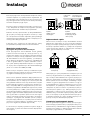
A
Rysunek A
Przyk∏ady otworów
wentylacyjnych
pomieszczenie
sàsiednie
pomieszczenie, które
ma byç wentylowane
Rysunek B
Powi´kszenie szczeliny
wentylacyjnej pomi´dzy
oknem i pod∏ogà
komin lub rozga∏´ziony
kana∏ dymowy
bezpoÊrednio na zewnàtrz
(w przypadku kuchenek)

PL
Uwaga: Kuchnia w klasie X nie mo˝e byç zabudowana wy-
sokim meblem. Jednak w ka˝dym przypadku meble do za-
budowy muszà mieç ok∏adzin´ oraz klej do jej przyklejenia
odporny na temperatur´ 100°C. Niespe∏nienie tego warun-
ku mo˝e spowodowaç zdeformowanie powierzchni lub od-
klejenia ok∏adziny. Je˝eli nie mamy pewnoÊci, co do odpor-
noÊci termicznej mebli, kuchni´ nale˝y zabudowaç mebla-
mi zachowujàc odst´p ok. 2 cm.
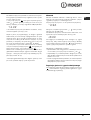
! Âciana znajdujàca si´ za kuchnià powinna byç uodpornio-
na na wysokie temperatury. Podczas korzystania z kuchni, jej
tylna Êciana mo˝e rozgrzaç si´ do temperatury oko∏o 90°C.
W∏aÊciwa instalacja kuchni wymaga uwzgl´dnienia
poni˝szych kwestii:
• Kuchni´ mo˝na zainstalowaç w kuchni, kuchnio-jadalni
lub pokoju spe∏niajàcym warunki techniczne wynikajàce
z przytoczonych przepisów; nie wolno jej instalowaç w ∏a-
zience ani w pomieszczeniu z prysznicem.
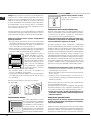
• Meble znajdujàce si´ obok kuchni, które wystajà powy˝ej
powierzchni kuchni, powinny znajdowaç si´ w odleg∏oÊci,
co najmniej 200 mm od kraw´dzi p∏yty z palnikami.
• Szafki sàsiadujàce z okapem
powinny znajdowaç si´ w odle-
g∏oÊci, co najmniej 420 mm od
powierzchni kuchni. Minimalna
odleg∏oÊç nad poziomem palni-
ków, w jakiej mogà byç moco-
wane elementy umeblowania
kuchni wykonane z materia∏ów
niezabezpieczonych termicznie
wynosi 700 mm.
• Nie stosowaç zas∏on z ty∏u kuchni i w odleg∏oÊci nie
mniejszej ni˝ 200 mm od jej boków.
• Okapy nale˝y montowaç zgodnie z instrukcjami podany-
mi w do∏àczonych do nich instrukcjach obs∏ugi, ale nie ni-
˝ej ni˝ 650 mm.
Kuchnia ma nast´pujàcà technicznà specyfikacj´:
Kat. II2ELs3B/P
Poziomowanie kuchni
Kuchenka wyposa˝ona jest w nó˝-
ki o zmiennej wysokoÊci umo˝liwia-
jàce odpowiednie wypoziomowa-
nie urzàdzania. JeÊli jest to koniecz-
ne nale˝y wkr´ciç lub wykr´ciç
nó˝ki znajdujàce si´ w naro˝nikach
podstawy kuchenki a˝ do uzyska-
nia w∏aÊciwego wypoziomowania.
Monta˝ nó˝ek (niektóre modele)
Przyrzàd do montowania nó˝ek
w podstawie kuchni
Pod∏àczenie do instalacji elektrycznej
Kuchenki, które wyposa˝one sà w trójbiegunowy kabel za-
silajàcy przystosowane sà do zasilania pràdem zmiennym
o parametrach podanych na tabliczce znamionowej
(umieszczonej we wn´ce pod piekarnikiem).
Uwaga: Do zasilania kuchni nie nale˝y stosowaç trans-
formatorów, przejÊciówek ani boczników, gdy˝ mogà
si´ one nadmiernie nagrzewaç lub zapaliç.
Na kablu zasilajàcym nale˝y zamontowaç standardowà
wtyczk´, odpowiadajàcà maksymalnemu obcià˝eniu, które
podano na tabliczce znamionowej. Ewentualnie, pod∏àczyç
urzàdzenie bezpoÊrednio do instalacji elektrycznej. W tym
przypadku nale˝y dodatkowo zamontowaç jednobiegunowy
wy∏àcznik sieciowy o odleg∏oÊci styków, co najmniej 3 mm
i odpowiadajàcy obowiàzujàcym przepisom bezpieczeƒstwa
(przewód uziemiajàcy nie mo˝e byç roz∏àczany przez wy∏àcz-
nik). Wy∏àcznik ten b´dzie odcina∏ kuchenk´ od zasilania. Ka-
bel zasilajàcy powinien byç u∏o˝ony w taki sposób, aby tem-
peratura w ˝adnym punkcie jego powierzchni nie mog∏a
przekroczyç temperatury pokojowej powi´kszonej o 50°C.
Przed wykonaniem po∏àczenia nale˝y sprawdziç czy:
• Urzàdzenie posiada obwód ochronny i wtyczk´ zgodnà
z obowiàzujàcymi przepisami.
• Bezpiecznik oraz instalacja elektryczna wytrzymajà obcià-
˝enie kuchenki.
• Instalacja elektryczna wyposa˝ona jest w skuteczny sys-
tem uziemiajàcy spe∏niajàcy wymagania aktualnych stan-
dardów i przepisów.
! Wtyczka lub wy∏àcznik sieciowy muszà byç ∏atwo dost´p-
ne po zainstalowaniu kuchenki.
! Przewód zasilajàcy nie mo˝e byç zagi´ty lub przygnieciony.
! Przewód zasilajàcy musi byç regularnie sprawdzany i w ra-
zie usterki wymieniony przez autoryzowanego technika.
! Producent nie ponosi ˝adnej odpowiedzialnoÊci za
ewentualne szkody wynik∏e z niew∏aÊciwego zainsta-
lowania urzàdzenia.
Pod∏àczenie gazu do kuchni
Uwaga: CzynnoÊç ta mo˝e byç wykonana jedynie przez
technika z odpowiednimi uprawnieniami, autoryzowa-
nego przez producenta.
Pod∏àczyç kuchni´ do butli gazowej lub rury instalacji gazo-
wej, przestrzegajàc obowiàzujàcych przepisów, wy∏àcznie po
uprzednim ustaleniu, czy kuchnia mo˝e byç zasilana gazem
wyst´pujàcym w danej instalacji. JeÊli jest inaczej, nale˝y wy-
16
HOOD
420
Min.
min.
650
mm. with hood
min.
700
mm. without hood
mm.
600
Min. mm.
420
Min. mm.
Klasa 2 podklasa 1
Klasa 1

konaç zalecania podane w cz´Êci „Dostosowywanie kuchen-
ki do ró˝nych rodzajów gazów”. Niektóre modele kuchenki
umo˝liwiajà pod∏àczenie instalacji gazowej z lewej lub prawej
strony kuchenki – aby zmieniç stron´ zasilania nale˝y zamie-
niç po∏o˝enie uchwytu w´˝a i korka zamykajàcego oraz wy-
mieniç uszczelk´ (do∏àczonà do kuchni). W przypadku pod-
∏àczenia do butli z gazem p∏ynnym nale˝y zastosowaç regu-
lator ciÊnienia, spe∏niajàcy obowiàzujàce przepisy.
Wa˝ne: nale˝y sprawdziç czy ciÊnienie gazu w instalacji
zgodne jest z zaleceniami podanymi w tabeli 1 zatytu∏owa-
nej „Parametry dysz i palników”. Zapewni to bezpiecznà
prac´ kuchni, w∏aÊciwe zu˝ycie gazu oraz przed∏u˝y czas
bezawaryjnej pracy kuchni.
Pod∏àczenie do sztywnej instalacji rurowej
(miedzianej lub stalowej)
Pod∏àczenie do instalacji gazowej powinno byç wykonane
w taki sposób, który nie wywo∏uje napr´˝eƒ w ˝adnym
punkcie instalacji ani na ˝adnej cz´Êci urzàdzenia.
Urzàdzenie wyposa˝one jest w regulowanà z∏àczk´
w kszta∏cie litery “L” oraz uszczelk´, które umo˝liwiajà pod-
∏àczenie do instalacji gazowej. Je˝eli zajdzie potrzeba prze-
kr´cenia z∏àczki to wymagana b´dzie równie˝ wymiana
uszczelki (do∏àczonej do urzàdzenia).
Z∏àcze doprowadzajàce gaz do kuchenki to m´ski cylinder
z gwintem 1/2.
Pod∏àczenie do elastycznego przewodu metalowego
Z∏àcze doprowadzajàce gaz do kuchenki to z∏àcze m´skie
zgwintem 1/2 do rur gazowych o przekroju okràg∏ym. Do
pod∏àczenia nale˝y stosowaç wy∏àcznie rury i uszczelki od-
powiadajàce aktualnie obowiàzujàcym normom. Maksy-
malna d∏ugoÊç przewodu elastycznego nie mo˝e przekra-
czaç 2000 mm. Po wykonaniu po∏àczenia nale˝y sprawdziç
czy elastyczny przewód metalowy nie styka si´ z ˝adnymi
cz´Êciami ruchomymi ani czy nie jest niczym przyciÊni´ty.
Pod∏àczenie w´˝em elastycznym
Kuchni´ gazowà pod∏àczamy w´˝em elastycznym tylko
w przypadku zasilania gazem p∏ynnym z butli gazowej.
W celu po∏àczenia króçca kuchni z w´˝em elastycznym na-
le˝y zastosowaç, co najmniej 0.5 m odcinek rury stalowej
instalacyjnej, która uniemo˝liwi zetkni´cie si´ w´˝a z gorà-
cymi Êcianami kuchni.
Do pod∏àczenia nale˝y zastosowaç wà˝ gazowy odpowia-
dajàcy wymaganiom okreÊlonym przez krajowe normy. Je-
Êli kuchenka zasilana jest gazem p∏ynnym nale˝y zastoso-
waç regulatory ciÊnienia, które spe∏niajà krajowe przepisy
techniczne. Wewn´trzna Êrednica w´˝a powinna wynosiç:
• 8 mm, w przypadku zasilania gazem p∏ynnym
Sprawdziç czy wà˝ jest ÊciÊle dopasowany na obu koƒcach.
Do zamocowania w´˝a u˝yç standardowych zacisków,
G∏ównymi postanowienia obowiàzujàcych norm technicz-
nych przewidujà, ˝e:
• wà˝ nie powinien w ˝adnym punkcie stykaç si´ z „goràcy-
mi” elementami kuchenki;
• wà˝ nie powinien byç d∏u˝szy ni˝ 1,5 metra
• wà˝ nie powinien byç w ˝adnym miejscu zgi´ty ani nacià-
gni´ty, na ca∏ej swojej d∏ugoÊci nie powinien równie˝ po-
siadaç ciasnych zakr´tów ani zw´˝eƒ
• na ca∏ej swojej d∏ugoÊci wà˝ powinien byç dost´pny, tak,
aby mo˝liwa by∏a kontrola jego zu˝ycia
• w przypadku wykrycia nieszczelnoÊci wà˝ powinien byç
ca∏kowicie wymieniony; naprawianie nieszczelnego w´˝a
jest zabronione
Sprawdzanie szczelnoÊci
Wa˝ne: Po zakoƒczeniu instalacji kuchenki nale˝y spraw-
dziç szczelnoÊç wszystkich po∏àczeƒ stosujàc do tego wo-
d´ z myd∏em. Do sprawdzania szczelnoÊci nie wolno w ˝ad-
nym wypadku stosowaç ognia!
Dostosowywanie kuchenki
do ró˝nych rodzajów gazów
Aby dostosowaç kuchenk´ do gazu innego rodzaju, ni˝ ro-
dzaj, dla którego zaprojektowano kuchenk´ (patrz naklejka
na spodzie kuchenki lub na opakowaniu), nale˝y wymieniç
dysze palników, zgodnie z poni˝szà procedurà:
1. Zdemontowaç krat´ podpierajàcà garnki i wysunàç pal-
niki z kuchenki
2. Za pomocà klucza nasadowego
7mm odkr´ciç dysze i wymieniç je
na nowe dysze, odpowiednie do
gazu danego typu (patrz Tabela 1,
„Parametry dysz i palników”).
3. Ponownie zmontowaç razem cz´-
Êci, wykonujàc wy˝ej opisane
czynnoÊci w odwrotnej kolejnoÊci
Regulacja dop∏ywu powietrza do palnika
Palniki nie wymagajà takiej regulacji.
Regulacja minimalnej wielkoÊci p∏omienia
1. Ustawiç zawór gazu w po∏o˝eniu najmniejszego p∏omienia
2. Zdemontowaç pokr´t∏o i przekr´ciç Êrub´ regulacyjnà
(znajdujàcà si´ bàdê po jednej ze stron trzonka lub w je-
go Êrodku). Przekr´ciç Êrub´ w kierunku zgodnym z ru-
chem wskazówek zegara do po∏o˝enia, w którym p∏o-
mieƒ b´dzie ma∏y i stabilny.
3. Sprawdziç czy p∏omieƒ nie gaÊnie podczas szybkiego
kr´cenia zaworem
4. W przypadku niew∏aÊciwego dzia∏ania kuchenek wypo-
sa˝onych w urzàdzenie zabezpieczajàce (termoelement)
przy ustawieniu najmniejszego p∏omienia, nale˝y zwi´kszyç
wielkoÊç p∏omienia za pomocà Êruby.
! W przypadku zasilania gazem p∏ynnym, Êruba regulacyj-
na powinna byç ca∏kowicie wkr´cona do samego koƒca.
! Po zakoƒczonej regulacji, nale˝y zmieniç nalepk´ z opi-
sem rodzaju gazu, do jakiego kuchnia jest przystosowana.
! JeÊli ciÊnienie gazu w instalacji ró˝ni si´ od wartoÊci, po-
danych w niniejszej instrukcji, nale˝y zastosowaç regulator
ciÊnienia.
17
PL

PL
18
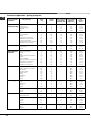
* przy gazie suchym 15°C 1013 mbar
G20 (GZ 50) p.c.i. 37,78 Mj/m
3
GZ350 (GZ35) p.c.i. 27,20 Mj/m
3
G30 (GPB) p.c.i. 125,81 Mj/m
3
K3G76/U
K3G76S/U
K3T76/U
K3T76S/U
Palnik
Szybki (du˝y – R)
Âredniej pr´dkoÊci (Êredni – S)
Pomocniczy (ma∏y – A)
CiÊnienie gazu
Ârednica
(mm)
Moc
termiczna
(p.c.i*)
Min.
Moc
termiczna
(p.c.i*)
Nominalna
Moc
termiczna
(p.c.i*)
Nominalna
Dysza
1/100
(mm)
Przep∏yw*
l/h
G20 (GZ50) G2.350 (GZ350)
Dysza
1/100
(mm)
Przep∏yw*
l/h
Dysza
1/100
(mm)
Przep∏yw*
g/h
100 0,70 128 286 158 397 3,40 87 247
75 0,40 104 181 143 251 2,20 70 160
51
0,40
76 95 106 132 1,30 52 95
Minimalne
Nominalne (mbar)
Maksymalne
16
20
25
10
13
16
29
36
44
Potrójna korona (TC)
130 1,50
3,00
1,90
1,00
3,25133309 1974303,6091262
Gaz naturalny
G30 (GPB)
Gaz p∏ynny
Parametry dysz i palników
Niniejsze urzàdzenie spe∏nia poni˝sze
dyrektywy Unii Europejskiej:
73/23/EEC z dn. 19/02/73 (Niskie na-
pi´cia) wraz z póêniejszymi zmianami
• 89/336/EEC z dn. 03/05/89 (Kompa-
tybilnoÊç elektromagnetyczna) wraz
z póêniejszymi zmianami
• 90/396/EEC z dn. 29/06/90 (Gazowa)
wraz z póêniejszymi zmianami
• 93/68/EEC z dn. 22/07/93 wraz
z póêniejszymi zmianami
• 2002/96/EEC
Uwaga: Tabliczka znamionowa umiesz-
czona jest na spodzie kuchni.
Drying:
DANE TECHNICZNE
Mogà byç dostosowane do ró˝nych
rodzajów gazu, zgodnie z informacjà
przedstawionà na tabliczce znamionowej,
znajdujàcej si´ na:
– wewn´trznej stronie drzwiczek schowka;
– wewn´trznej stronie lewego boku kuchni
widoczna po wysuni´ciu szuflady.
Zobacz tabliczk´ znamionowà
Etykieta energetyczna jest zgodna
z Dyrektywà UE 2002/40/CE (norma EN
50304).
Energoch∏onnoÊç podana w oparciu
o nastawy piekarnika:
– pieczenie statyczne:
wybrana funkcja Tryb konwencjonalny
Deklarowana klasa energoch∏onnoÊci
podana dla trybu dynamicznego
– pieczenie dynamiczne:
wybrana funkcja „Pieczenie ciast”
szerokoÊç 44 cm
wysokoÊç 34 cm
g∏´bokoÊç 38 cm
szerokoÊç 42 cm
wysokoÊç 23 cm
g∏´bokoÊç 44 cm
54 litry
S
S
R
A
S
S
TC
A
Palniki
Napi´cie
i cz´stotliwoÊç
zasilania
Etykieta
energetyczna
Wymiary
piekarnika
PojemnoÊç
piekarnika
Szuflada/
schowek kuchni

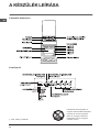
Opis kuchni
19
PL
Ogólny widok
Palniki gazowe P∏yta podpalnikowa
poziom 5
PROWADNICE
do wsuwania rusztu i tacy
poziom 3
poziom 4
poziom 2
poziom 1
Regulowane nó˝ki
Kontrolka TERMOSTATU
Pokr´t∏o TERMOSTATU
piekarnika
Elektroniczny
programator*
Przycisk
CZASU PIECZENIA
Przycisk MINUTNIKA
Przycisk
ZAKO¡CZE
NIA CZASU
PIECZENIA
Pokr´t∏o
OPCJI
PRACY
piekarnika
Pokr´t∏a kurków
gazowych
PALNIKÓW
Ruszt
Panel sterujàcy
KRATKA piekarnika
TACA na kapiàcy
t∏uszcz
lub do pieczenia
Regulowane nó˝ki
* Dost´pne w niektórych modelach.
UWAGA! Szklana pokrywa może
popękać jeżeli zostanie nagrzana.
Należy wyłączyć wszystkie palniki
przed zamknięciem pokrywy. *Dotyczy
tylko modeli ze szklana pokrywa.

Uruchomienie
i obs∏uga kuchni
PL
Pokr´t∏a oznaczone sà symbolami okreÊlajàcymi przypo-
rzàdkowanie palników gazowych lub p∏ytek elektrycznych
(o ile urzàdzenie jest w nie wyposa˝one).
Palnik gazowe
Palniki te ró˝nià si´ pod wzgl´dem wymiarów i mocy. Do
przygotowywania posi∏ku nale˝y u˝yç palnika o wymiarze
najbardziej zbli˝onym do rozmiarów stosowanego garnka.
Aby w∏àczyç palnik nale˝y:
1. Zbli˝yç zapalonà zapa∏k´ lub zapalniczk´ do palnika.
2. Ca∏kowicie wcisnàç pokr´t∏o i przekr´ciç je w kierunku
przeciwnym do ruchu wskazówek zegara – w po∏o˝enie
oznaczone symbolem du˝ego p∏omienia .
3. Ustawiç ˝àdanà moc palnika przez ustawienie pokr´t∏a
we w∏aÊciwej pozycji.
Dost´pne sà nast´pujàce po∏o˝enia:
•
– pozycja wy∏àczona
– po∏o˝enie maksymalne
– po∏o˝enie minimalne
Je˝eli kuchenka wyposa˝ona jest
welektrycznà zapalark´, to ˝eby za-
paliç palnik w takiej kuchence nale˝y
wcisnàç do koƒca odpowiednie po-
kr´t∏o i przekr´ciç je w po∏o˝enie du-
˝ego p∏omienia przytrzymujàc je wci-
Êni´te a˝ do zapalenia si´ gazu.
W modelach wyposa˝onych w urzàdzenie zabezpieczajàce
nale˝y przytrzymaç pokr´t∏o wciÊni´te przez oko∏o 3 se-
kund, do momentu a˝ czujnik urzàdzenia zabezpieczajàce-
go nagrzeje si´ i zacznie podtrzymywaç p∏omieƒ.
! Ostro˝nie: Je˝eli palnik przypadkowo zgaÊnie nale˝y, ko-
rzystajàc z pokr´t∏a, zakr´ciç dop∏yw gazu. Przed przystà-
pieniem do ponownego zapalania gazu nale˝y odczekaç,
co najmniej jednà minut´.
Aby wy∏àczyç palnik, nale˝y przekr´ciç pokr´t∏o w kierunku
zgodnym z ruchem wskazówek zegara, do koƒcowego po-
∏o˝enia (pokr´t∏o nale˝y zostawiç w po∏o˝eniu, oznaczonym
symbolem
•
).
Praktyczne porady dotyczàce
korzystania z palników
Poni˝sze wskazówki umo˝liwià Paƒstwu uzyskanie najlep-
szych rezultatów w u˝ytkowaniu kuchenki:
• Na ka˝dym z palników nale˝y stawiaç garnki i naczynia
o rozmiarach odpowiednich do rozmiaru palnika (patrz ta-
bela). Dzi´ki temu p∏omieƒ podgrzewa∏ b´dzie jedynie
dno naczynia i nie b´dzie opala∏ jego boków;
• Nale˝y zawsze stosowaç garnki o p∏askich dnach, i przy-
krywaç je pokrywkami;
• Gdy zawartoÊç naczynia zacznie si´ gotowaç nale˝y
zmniejszyç p∏omieƒ przekr´cajàc pokr´t∏o w po∏o˝enie
„niski p∏omieƒ”.
UWAGA: W niektórych modelach wyst´puje redukcyjna
podstawka. Mo˝e ona byç stosowana jedynie na palniku po-
mocniczym A dla garnków o Êrednicy mniejszej ni˝ 12 cm.
Korzystanie z piekarnika
! Przed pierwszym u˝yciem piekarnika i grilla nale˝y urzà-
dzenie wygrzaç. Wygrzewanie powinno trwaç oko∏o pó∏ go-
dziny. W tym czasie piekarnik powinien byç pusty, termostat
powinien byç ustawiony na najwy˝szà temperatur´, drzwi
powinny byç otwarte. Nale˝y równie˝ zapewniç odpowied-
nià wentylacj´ kuchni. Zapach, który odczuwany jest za
zwyczaj podczas wygrzewania kuchenki, zwiàzany jest
z parowaniem substancji wykorzystywanych do zabezpie-
czenia piekarnika na czas magazynowania.
! Przed uruchomieniem kuchni nale˝y usunàç foli´ zabez-
pieczajàcà boczne Êcianki urzàdzenia.
! Dolnà pó∏k´ nale˝y wykorzystywaç podczas pieczenia na
ro˝nie. W przypadku innych opcji piekarnika nie nale˝y sto-
sowaç dolnej pó∏ki.
! Nie nale˝y nic k∏aÊç na dolnej cz´Êci piekarnika podczas
pracy urzàdzenia – mo˝e to spowodowaç uszkodzenie ema-
lii. Do pieczenia nale˝y u˝ywaç wy∏àcznie kratk´ piekarnika.
! W kuchni wyposa˝onej w elektroniczny programator przed
uruchomieniem piekarnika nale˝ najpierw jednoczeÊnie
wcisnàç przyciski i (na wyÊwietlaczu pojawi si´
symbol )
1. Pokr´t∏em OPCJI PRACY piekarnika wybraç program
pieczenia.
2. Pokr´t∏em TERMOSTATU ustawiç temperatur´ pieczenia.
(zobacz tabel´ z Poradnikiem pieczenia)
W trakcie pieczenia mo˝liwe jest:
• Zmiana programu pieczenia przez obrócenie pokr´t∏em
OPCJI PRACY piekarnika.
• Zmiana temperatury pieczenia przez obrócenie pokr´t∏em
TERMOSTATU.
• Wy∏àczenie pieczenia przez ustawienie pokr´t∏a OPCJI
PRACY piekarnika w pozycji „0”.
! Pieczenie musi odbywaç si´ na KRATCE.
Kontrolka pracy TERMOSTATU
Sygnalizuje moment, w którym piekarnik grzeje. W momen-
cie osiàgni´cia zadanej temperatury pokr´t∏em termostatu
kontrolka zgaÊnie. W∏àczy si´ ponownie, kiedy grza∏ki zno-
wu zacznà grzaç a˝ do osiàgni´cia temperatury, kiedy zno-
wu zgaÊnie. Kontrolka informuje o prawid∏owej pracy termo-
statu, który czuwa nad utrzymaniem sta∏ej temperatury
w piekarniku.
E
20
Palnik º Êrednica naczyƒ (cm)
Szybki (R) 24 – 26
Pó∏-szybki (S) 16 – 20
Pomocniczy (A) 10 – 14
Potrójna korona (TC) 24 – 26
Strona jest ładowana ...
Strona jest ładowana ...
Strona jest ładowana ...
Strona jest ładowana ...
Strona jest ładowana ...
Strona jest ładowana ...
Strona jest ładowana ...
Strona jest ładowana ...
Strona jest ładowana ...
Strona jest ładowana ...
Strona jest ładowana ...
Strona jest ładowana ...
Strona jest ładowana ...
Strona jest ładowana ...
Strona jest ładowana ...
Strona jest ładowana ...
Strona jest ładowana ...
Strona jest ładowana ...
Strona jest ładowana ...
Strona jest ładowana ...
-
 1
1
-
 2
2
-
 3
3
-
 4
4
-
 5
5
-
 6
6
-
 7
7
-
 8
8
-
 9
9
-
 10
10
-
 11
11
-
 12
12
-
 13
13
-
 14
14
-
 15
15
-
 16
16
-
 17
17
-
 18
18
-
 19
19
-
 20
20
-
 21
21
-
 22
22
-
 23
23
-
 24
24
-
 25
25
-
 26
26
-
 27
27
-
 28
28
-
 29
29
-
 30
30
-
 31
31
-
 32
32
-
 33
33
-
 34
34
-
 35
35
-
 36
36
-
 37
37
-
 38
38
-
 39
39
-
 40
40


Indesit K3G76S(X)/U instrukcja
- Kategoria
- Mikrofale
- Typ
- instrukcja
- Ten podręcznik jest również odpowiedni dla
w innych językach
- français: Indesit K3G76S(X)/U Mode d'emploi
- English: Indesit K3G76S(X)/U User guide
Powiązane dokumenty
-
Indesit K3M5(W)/U instrukcja
-
Whirlpool K3G66S(W)/U instrukcja
-
Indesit K3G55.A(W)/U instrukcja
-
-
-
-
-
-
-