
automatic
e
de Deutsch 2
en English 9
pl Polski 15
tr Türkçe 21
DH18100
DH21100
DH24100
9001155285
Montage- und
Gebrauchsanleitung
Installation and
operating instructions
Instrukcja montażu
i użytkowania
Montaj ve Kullanma
Kılavuzu

2
de
Sicherheitshinweise
Dieses Gerät ist für den Haushalt oder für
haushaltsähnliche, nicht gewerbliche Anwen-
dungen bestimmt. Haushaltsähnliche An-
wendungen umfassen z. B. die Verwendung
in Mitarbeiterküchen von Läden, Büros, land-
wirtschaftlichen und anderen gewerblichen
Betrieben, sowie die Nutzung durch Gäste
von Pensionen, kleinen Hotels und ähnlichen
Wohneinrichtungen.
■ Das Gerät wie in Text und Bild beschrie-
ben montieren und bedienen. Wir über-
nehmen keine Haftung für Schäden, die
durch Nichtbeachtung dieser Anleitung
entstehen.
■ Dieses Gerät ist für den Gebrauch bis zu
einer Höhe von 2 000 m über dem Meeres-
spiegel bestimmt.
■ Das Gerät nur in einem frostfreien Raum
installieren und lagern (Restwasser).
Stromschlaggefahr!
Schalten Sie im Fehlerfall sofort die
Netzspannung ab.
Bei einer Undichtigkeit am Gerät sofort
die Kaltwasser zuleitung schließen.
■ Der Durchlauferhitzer darf nur von einem
Fachmann angeschlossen und in Betrieb
genommen werden.
■ Um Gefährdungen zu vermeiden, dür-
fen Reparaturen und Wartung nur von
einem Fachmann durchgeführt werden.
■ Öffnen Sie niemals das Gerät, ohne die
Stromzufuhr zum Gerät unterbrochen zu
haben.
■ Die gesetzlichen Vorschriften des jeweili-
gen Landes, des örtlichen Elektrizitäts-Ver-
sorgungsunternehmens und des Wasser-
werkes müssen eingehalten werden.
■ Der Durchlauferhitzer ist ein Gerät der
Schutzklasse I und muss an den Schutz-
leiter angeschlossen werden.
■ Das Gerät muss dauerhaft an festverlegte
Leitungen angeschlossen werden. Der Lei-
tungsquerschnitt muss der zu installie-
renden Leistung entsprechen.
■ Vorsicht: Geerdete Wasserleitungen kön-
nen das Vorhandensein eines Schutzleiters
vortäuschen.
■ Zur Erfüllung der einschlägigen Sicher-
heitsvorschriften muss installationsseitig
eine allpolige Trennvorrichtung vorhanden
sein. Die Kontaktöffnung muss mindestens
3 mm betragen.
■ Der Durchlauferhitzer ist nur für den
geschlossenen (druckfesten) Betrieb
geeignet.
■ Armaturen müssen für den Betrieb mit
geschlossenen (druckfesten) Durchlauf-
erhitzern zugelassen sein.
■ Den Durchlauferhitzer nur an eine Kalt-
wasserleitung anschließen. Ein Rückfluss-
verhinderer in der Kaltwasserleitung ist
nicht zulässig.
■ Nie Kunststoffrohre verwenden. Als Kalt-
wasserzuleitung sind Stahl- oder Kupfer-
rohre geeignet. Für die Warmwasserleitung
sind wärmegedämmte Kupferrohre beson-
ders geeignet.
■ Das Gerät sollte nahe an der Entnahme-
stelle montiert werden, die am meisten
benutzt wird.
■ Das elektrische Anschlusskabel vor der
Montage spannungslos machen und die
Wasserzuleitung absperren!
■ Den Elektroanschluss erst nach dem
Wasseranschluss durchführen.
■ In der Rückwand nur die Öffnungen her-
stellen, die für die Montage benötigt wer-
den. Bei erneuter Montage müssen die
unbenutzten Öffnungen wasserdicht ver-
schlossen werden.
■ Spannungsführende Teile dürfen nach der
Montage nicht mehr berührbar sein.
■ Bei Arbeiten am Wassernetz das Gerät vom
elektrischen Netz trennen. Nach Abschluss
der Arbeiten wie bei der ersten Inbetrieb-
nahme vorgehen.
■ Am Gerät dürfen keine Veränderungen
vorgenommen werden.
■ Das Gerät darf nur zur Erwärmung von
Trinkwasser im Hausgebrauch verwendet
werden.

3
de
■ Dieses Gerät kann von Kindern ab 8 Jahren
und darüber sowie von Personen mit verrin-
gerten physischen, sensorischen oder men-
talen Fähigkeiten oder Mangel an Erfahrung
und Wissen benutzt werden, wenn sie be-
aufsichtigt oder bezüglich des sicheren Ge-
brauchs des Gerätes unterwiesen wurden
und die daraus resultierenden Gefahren ver-
stehen. Kinder dürfen nicht mit dem Gerät
spielen. Reinigung und Benutzer-Wartung
dürfen nicht von Kindern ohne Beaufsichti-
gung durchgeführt werden.
■ Kinder vom Gerät fern halten.
■ Kinder beaufsichtigen, um zu verhindern,
dass sie mit dem Gerät spielen.
■ Die Mischbatterie und das Warmwasser-
rohr können heiß werden. Kinder darauf
hinweisen.
■ Keine Scheuermittel oder anlösende
Reinigungsmittel verwenden.
■ Keinen Dampfreiniger benutzen.
■ Das Entkalken des Gerätes darf nur durch
einen Fachmann erfolgen.
Herzlichen Glückwunsch zum Kauf dieses Geräts aus unse-
rem Hause Siemens. Sie haben ein hochwertiges Produkt
erworben, das Ihnen viel Freude bereiten wird.
Die Montage- und Gebrauchsanleitung bitte sorgfältig
durchlesen, danach handeln und aufbewahren!
Montageanleitung
Montieren Sie den Durchlauferhitzer, wie im Bildteil
beschrieben. Beachten Sie die Hinweise im Text.
Die Bildseiten finden Sie in der Mitte der Anleitung.
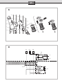
Montage
I.
Lieferumfang
1 Durchlauferhitzer
2 Montageschablone
3 Auslaufstutzen für Warmwasser
4 Dichtung, rot Ø 15 mm
5 Zulaufstutzen für Kaltwasser
6 Dichtung, Ø 24 mm
7 Montageschraube
8 Dübel
9 Befestigungsmutter
10 Gewindebuchse
11 Leitungstülle
II.
Wandmontage
Es gibt 2 Möglichkeiten, den Durchlauferhitzer an der Wand
zu befestigen:
– Mit der Montageschraube: Wandunebenheiten bis zu
25 mm können ausgeglichen werden.
– Anhand von bereits vorhandenen Bohrungen des alten
Gerätes: Prüfen Sie mit der Montageschablone, ob die vor-
handenen Bohrungen passen.
Im Folgenden wird die Befestigung mit der Montageschraube
beschrieben.
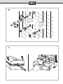
Befestigungspunkt anzeichnen und Öffnung zur Kabel-
einführung auswählen (Bild A)
Achtung!
Vergewissern Sie sich, dass das elektrische
Anschlusskabel spannungsfrei ist!
■ Öffnung 3 der Montageschablone über den Kaltwasser-
zulauf legen.
■ Günstigste Öffnung für die Kabeleinführung auswählen:
Das elektrische Anschlusskabel darf nur durch eine der
sechs Öffnungen 14.. geführt werden. Wird es durch eine
der unteren Öffnungen 14a in den Durchlauferhitzer ein-
geführt, kann die Zwischenklemme BZ 45Z20 (Sonderzu-
behör) verwendet werden.
■ Befestigungspunkt 12 für die Montageschraube anzeichnen.
Montageschraube anbringen und Wasserstutzen
einschrauben (Bild B)

4
de
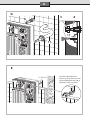
Gerät öffnen (Bild C)
Öffnungen in der Rückwand für die Montageschraube
und die Kabeleinführung ausbrechen
Achtung: Um das Gerät zu befestigen, dürfen Sie nur die
vorgesehenen Öffnungen an der Gehäuserückwand ausbre-
chen. Ausgebrochene, aber unbenutzte Öffnungen müssen
Sie wasserdicht verschließen.
Kabel einführen (Bild D)
■ Leitungstülle 11 auf das Anschlusskabel schieben.
Hinweis: Bei einem Leiterquerschnitt von 16 mm
2
die Lei-
tungstülle nicht verwenden. Das Gerät muss dann wandbün-
dig montiert werden.
Achtung: Ohne Leitungstülle besteht bei
DH18100/21100/24100 nur ein Spritzwasserschutz (IP 24).
■ Das Gerät auf das Anschlusskabel setzen.
■ Leitungstülle in die Gehäuserückwand eindrücken. Darauf
achten, dass die Dichtlippen an der Leitungseinführung
rundum anliegen.
■ Das Gerät auf die Gewindebuchse 8 setzen und mit Mut-
ter 9 verschrauben.
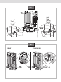
Wandunebenheiten ausgleichen (Bild E)
III.
Wasseranschluss
■ Mit der Feststellschraube 15 kann der Wasseranschluss
um ± 10 mm vertikal ausgerichtet werden.
■ Rohrbogen „warm“ an den Warmwasseranschluss anpas-
sen. Der Anschlusswinkel „kalt“ darf dabei nicht verbo-
gen werden.
Achtung: Darauf achten, dass ein Abstand von min. 6 mm zu
den stromführenden Teilen vorhanden ist.
■ Wasseranschlüsse verschrauben und Befestigungsmutter
an der Montageschraube festziehen.
Dichtheit prüfen und Gerät durchspülen:
■ Warmwasserhahn öffnen.
■ Alle Rohrverschraubungen auf Dichtheit prüfen.
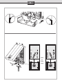
IV.
Elektroanschluss
■ Der Elektroanschluss 400 V 3 ~ darf grundsätzlich erst
nach dem Wasseranschluss erfolgen. Er ist entsprechend
dem Schaltbild auf der Innenseite der Abdeckhaube
auszuführen.
■ Zur Erfüllung der einschlägigen Sicherheitsvorschriften
muss installationsseitig eine allpolige Trennvorrichtung
vorhanden sein. Die Kontaktöffnung muss mindestens
3 mm betragen.
■ Wird das elektrische Anschlusskabel durch die unteren
Öffnungen 14a in den Durchlauferhitzer geführt, kann die
Zwischenklemme BZ 45Z20 (Sonderzubehör) verwendet
werden!
■ Die Leitungen dürfen den Auslöseknopf A des Sicherheits-
temperaturbegrenzers nicht in seiner Funktion behindern.
Installationshinweis
■ Die Installation nicht-steckerfertiger Geräte ist vom jewei-
ligen Netzbetreiber oder von einem eingetragenen Fach-
betrieb vorzunehmen, der Ihnen auch bei der Einholung
der Zustimmung des jeweiligen Netzbetreibers fur die
Installation des Gerätes behilflich ist.
V.
Gerät schließen
■ Wenn Sie den Gehäusedeckel aufsetzen, achten Sie
auf die richtige Zuordnung von Schalterstellung und
Schalterachse.
VI.
Inbetriebnahme
Das Gerät stimmt mit IEC 61000-3-12 überein.
■ Sicherungen für den Durchlauferhitzer in der Hausinstalla-
tion einschalten.
■ Stufe II am Gerät einstellen und Wassertemperatur
überprüfen.
Bei niedrigem Wasserleitungsdruck
■ Öffnen Sie mehrere Kaltwasserhähne und prüfen dann,
ob sich die Heizung einschaltet. Schaltet sich die Heizung
nicht ein, entfernen Sie den Durchflussbegrenzer (Bild A).
■ Erklären Sie dem Benutzer das Gerät, und übergeben Sie
ihm bitte die Gebrauchsanweisung.
Vorrangschaltung für die Kombination mit Elektro-
speicher-Heizgeräten (Bild B)
Für diesen Betrieb ist ein Vorrangschalter in die Phasenlei-
tung L2 des Gerätes zu schalten. Er wird auf der Zähler- bzw.
Verteilertafel montiert.
a, b Steuerleitung des Elektrizitätswerkes zum Spulen-
eingang des Aufladeschutzes
f1 Sicherheits-Temperaturbegrenzer mit
Netzanschlussklemmen
f3 Vorrangschalter (Stromrelais)
l1 Netzanschlussklemme (nur bei 21-kW- und
24-kW-Gerät)

5
de
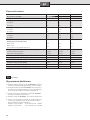
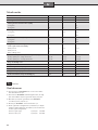
Technische Daten
DH18100 DH21100 DH24100
Nennleistung [kW]
18 21 24
Nennspannung
400 V 3 ~ 400 V 3 ~ 400 V 3 ~
Heizleistung Sparstellung e [kW]
1. Stufe 6 7 8
2. Stufe 12 14 16
Heizleistung Starkheizung II [kW]
1. Stufe 9 10,5 12
2. Stufe 18 21 24
Einschaltpunkt [l/min]
1. Stufe 4,0 4,5 5,0
2. Stufe 5,0 5,8 6,6
Mischwasser [l/min] bei Nennleistung
von ca. 38 °C 9,8 11,5 13,1
von ca. 50 °C
(Zulauftemperatur 12 °C)
6,7 7,8 9,0
Mindestfließdruck am Gerät* [MPa (bar)]
mit Durchflussbegrenzer 0,6 (6) 0,8 (8) 0,9 (9)
ohne Durchflussbegrenzer 0,4 (4) 0,5 (5) 0,6 (6)
Energieeffizienzklasse
BBB
Lastprofil
SSS
Jahresenergieverbrauch [kWh]
495 497 501
Täglicher Stromverbrauch [kWh]
2,301 2,313 2,337
Schallleistungspegel [dB]
15 15 15
Warmwasserbereitungs-Energieeffizienz [%]
37,2 37,1 36,8
* Hierzu kommt noch der Druckabfall an der Mischbatterie.
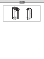
VII.
Abmessungen
Sonderzubehör
■ Rohrbausatz BZ 45K24: Zur Verwendung des Durchlauf-
erhitzers als Untertischgerät.
■ Zwischenklemme BZ 45Z20: Wird benötigt, wenn die
elektrische Anschlussleitung durch die untere Leitungs-
einführung 14a eingeführt wird.
■ Vorrangschalter (Lastabwurfrelais) BZ 45L21:
für den Betrieb mit Vorrangschaltung
■ Montageset BZ 45K24: für Aufputzinstallation
■ Gekürzte, und hinten verschlossene Anschlussstutzen für
den Wasseranschluss von unten (z. B. Kaltwasseranschluss
über eine untergebaute Armatur):
Kniestück „kalt“ (rechts) Bestell-Nr. 056169
Kniestück „warm“ (links) Bestell-Nr. 255568

6
de
Gebrauchsanleitung
Bitte die ausführlichen Sicherheitshinweise am Anfang
dieser Anleitung durchlesen und beachten!
■ Wichtig: Das Gerät niemals Frost aussetzen!
Stromschlaggefahr!
Schalten Sie im Fehlerfall sofort die Netzspannung
ab!
■ Bei einer Undichtigkeit am Gerät sofort die Kaltwasser-
zuleitung schließen.
Gerät kennenlernen
Der Durchlauferhitzer erwärmt das Wasser, während es durch
das Gerät fließt. Nur in dieser Zeit verbraucht das Gerät Strom.
Dieses Gerät kann auch mehrere Wasser-Entnahmestellen
mit warmem Wasser versorgen. Es sollte nahe an der Ent-
nahmestelle montiert werden, die Sie am meisten benutzen.
Dadurch sparen Sie Energie.
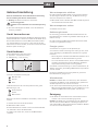
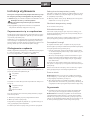
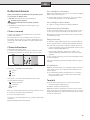
Gerät bedienen
Ihr Durchlauferhitzer hat zwei Stufen:
e Sparstufe – zwei Drittel Leistung
II Starkheizung – volle Leistung
automatic
e
Stufe e ist die ideale Einstellung für:
Waschbecken
Dusche
Bidet
Stufe II benutzen Sie für hohe Temperaturen oder große
Wassermengen, z.B.
Geschirrspülen
Putzen
Wannenbad
Wenn Sie eine Thermostatbatterie verwenden, stellen Sie auf
Stufe II.
1. Gewünschte Stufe e oder II einstellen.
2. Warmwasserhahn öffnen.
Der Durchlauferhitzer schaltet sich ein und erhitzt das Was-
ser, während es durch das Gerät fließt.
Er schaltet sich wieder aus, wenn Sie den Wasserhahn
schließen.
Wassertemperatur erhöhen
Bei ganz geöffnetem Wasserhahn reicht unter Umständen
die Leistung des Gerätes nicht aus, das Wasser auf die ge-
wünschte Temperatur zu erhitzen.
■ Wasserhahn etwas schließen. Das Wasser fließt langsamer
durch das Gerät und wird heißer.
Wassertemperatur senken
■ Kaltwasser zumischen.
Bedienungshinweis
Bei nur wenig geöffnetem Warmwasserhahn arbeitet der
Durchlauferhitzer in beiden vorgewählten Stufen (e, II) mit
halber Leistung.
Bei ganz geöffnetem Warmwasserhahn arbeitet das Gerät
mit voller, vorgewählter Leistung.
Energie sparen
■ Benutzen Sie möglichst oft die Sparstufe „e“.
Sie nutzen die elektrische Energie besonders gut aus, wenn
Sie bei Beendigung der Warmwasserentnahme Folgendes
beachten:
– Durch langsames Schließen des Warmwasserhahnes wird
die Restwärme des Durchlauferhitzers genutzt.
– Sie vermeiden damit auch, dass bei erneuter Warmwasser-
entnahme innerhalb der nächsten Minuten die Wasser-
temperatur kurzzeitig höher ist als vorgewählt.
Vorteilhaft ist die Verwendung von Thermostatbatterien, da
dadurch besonders gleichmäßige Warmwassertemperaturen
erreicht werden.
Die Thermostatbatterie muss für hydraulisch gesteuerte
Durchlauferhitzer geeignet sein.
Winterbetrieb
Hinweis: Im Winter kann es vorkommen, dass die Zulauf-
temperatur des Wassers sinkt und dadurch die gewünschte
Auslauftemperatur nicht mehr erreicht wird.
■ Um diese Temperaturabsenkung auszugleichen, bitte die
Wassermenge am Wasserhahn so weit reduzieren, bis die
gewünschte Warmwassertemperatur erreicht wird.
Reinigung
■ Das Gerät nur feucht abwischen. Verwenden Sie keine
scharfen oder scheuernden Reinigungsmittel.
Hinweis: Das Gerät muss normalerweise nicht entkalkt wer-
den. Bei extrem hartem Wasser und häufigem Zapfen von
sehr heißem Wasser kann das Gerät aber verkalken. Wenden
Sie sich an unseren Kundendienst.

7
de
Eine Störung, was tun?
Achtung!
Reparaturen dürfen nur vom Fachmann durchge-
führt werden. Sie setzen sich großer Gefahr aus,
wenn das Gerät unsachgemäß repariert wird.
Funktioniert Ihr Gerät nicht wie gewünscht, so liegt es oft
nur an einer Kleinigkeit. Bitte prüfen Sie, ob aufgrund fol-
gender Hinweise die Störung selbst behoben werden kann.
Sie vermeiden dadurch die Kosten für einen unnötigen
Kundendiensteinsatz.
Das Wasser erwärmt sich nicht oder es fließt zu wenig
Wasser:
■ Die Sicherung in der Hausinstallation überprüfen.
■ Druckabfall im Wasserleitungsnetz. Bei geringem Druck
schaltet sich das Gerät nicht ein.
■ Das Sieb am Wasserhahn oder am Brausekopf ist ver-
stopft. Sieb abschrauben und reinigen oder entkalken.
■ Das Eckregulierventil ist verstopft. Warmwasserhahn ganz
öffnen und Eckregulierventil mehrmals auf- und zudre-
hen. Anschließend das Sieb am Wasserhahn reinigen.
■ Das Gerät muss entkalkt werden. Rufen Sie bitte einen
Fachmann.
Das Gerät schaltet während der Wasserentnahme ab, die
Wassertemperatur sinkt:
■ Im Warmwasserhahn muss eine nicht quellende Dichtung
eingesetzt werden.
Wenn Sie die Störung nicht beheben können, schalten Sie
die Sicherung in der Hausinstallation aus. Rufen Sie einen
Fachmann.
Kundendienst
Wenn Sie den Kundendienst anfordern, geben Sie bitte die
E-Nummer und die FD-Nummer Ihres Gerätes an.
Sie finden die Nummern an der Unterseite des
Durchlauferhitzers.
Entsorgung
Dieses Gerät ist entsprechend der europäischen
Richtlinie 2012/19/EU über Elektro- und Elektronik-
altgeräte (waste electrical and elec tronic equip-
ment – WEEE) gekennzeichnet.
Die Richtlinie gibt den Rahmen für eine EU-weit
gültige Rücknahme und Verwertung der Alt geräte
vor.
Über aktuelle Entsorgungswege bitte beim Fach-
händler informieren.
Änderungen vorbehalten.

8
de
10/15

9
en
Safety information
This appliance is intended for domestic use
or for household-based, non-commercial
applications. Household-based applications
include, e.g. usage in employees catering
facilities for shops, offices, agricultural and
other commercial operations, as well as
usage by guests of guest houses, small hotels
and similar residential establishments.
■ Install and operate the appliance as de-
scribed in the text and illustrations. We do
not accept liability for damage resulting
from failure to heed these instructions.
■ This appliance is intended for use up to an
altitude of 2000 m above sea level.
■ The appliance may only be installed and
stored in a frost-free room (due to residual
water).
Risk of electric shock!
Switch off the mains voltage supply
immediately if a fault occurs.
Immediately shut off the cold water
supply to the appliance should it leak.
■ The continuous-flow heater may only be
connected and put into operation by a
qualified professional.
■ In order to avoid potential sources of
danger, repairs and maintenance may
only be undertaken by a suitably quali-
fied specialist.
■ Never open the appliance without discon-
necting the power supply beforehand.
■ The statutory regulations of the respective
country, as well as those of the local electric-
ity and water suppliers, must be adhered to.
■ The continuous-flow heater is a Class I
appliance and must be connected to the
protective earth.
■ The appliance must be permanently
connected to installed pipes. The conduc-
tor cross-section must comply with the
installed appliance power.
■ Caution: Earthed water pipes may give the
appearance of a connected protective earth.
■ To guarantee compliance to relevant safety
regulations, an all-pole separator must
be fitted during installation. The contact
opening must be at least 3
mm.
■ The continuous-flow heater is only suitable
for closed (pressurised) operation.
■ The tap and outlet fittings must be approved
for operation with closed (pressurised) con-
tinuous-flow heater systems.
■ Only connect the continuous-flow heater
to a cold water line. A non-return valve
must NOT be connected to the cold water.
■ Do not use plastic pipes. Steel or copper
pipes are suitable for the cold-water sup-
ply. Insulated copper pipes are particularly
suitable for the hot-water pipes.
■ The appliance should be installed
close to the tap that is used the most
frequently.
■ Disconnect the electrical connection cable
from the supply and shut off the water
supply before connecting the appliance!
■ Connect the water supply and then
connect the electrical supply.
■ Only make the openings which are re-
quired for installation on the rear of the
appliance. If the appliance is reinstalled,
the unused openings must be provided
with watertight sealing.
■ Do not touch electrically live parts after
installation.
■ The appliance should be disconnected
from the electrical mains supply when
working on the water supply. After service
work is complete, proceed as during the
first-time appliance start-up.
■ No changes may be made to the appliance.
■ The appliance may only be used for heat-
ing drinking water for household use.
■ This appliance can be used by children aged
8 years and older as well as by persons with
diminished bodily, sensory or mental percep-
tion, or those who lack knowledge or experi-
ence, if they are monitored or have received
instruction concerning use and comprehend
the possible dangers that can result. Chil-
dren may not play with the appliance. Clean-
ing and maintenance by the user may not
be performed by unsupervised children.
■ Keep children away from the appliance.
■ Please monitor children to ensure that they
do not play with the appliance.

10
en
Congratulations on purchasing this Siemens appliance. You
have acquired a top-quality product, which will give you a lot
of enjoyment.
Please read this installation and operating instruction
manual carefully, then act accordingly! Store for future
reference.
Installation instructions
Install the continuous-flow heater as described in the
illustrated section. Observe the instructions in the text.
The illustrations can be found in the centre of the instruction
manual.
Installation
I.
List of items supplied
1 Continuous-flow heater
2 Installation template
3 Connection piece for hot water
4 Washer, red Ø 15 mm
5 Connection piece for cold water
6 Washer, Ø 24 mm
7 Mounting bolt
8 Wall plug
9 Securing nut
10 Threaded bushing
11 Cable grommet
II.
Wall mounting
There are two ways in which the continuous-flow heater can
be mounted on the wall:
– Using the mounting bolt. Unevenness in the wall up to a
depth of 25 mm can be compensated for.
– Making use of the holes that were drilled for the old heater:
Use the mounting template to establish whether the exist-
ing holes line up properly.
The following describes the installation procedure using the
mounting bolt.
Marking the point for mounting the heater and selecting
the opening for the connecting cable (Fig. A)
Important!
Make sure that the connecting cable is isolated
from the mains electricity supply!
■ Place hole 3 in the mounting template over the cold-water
inlet.
■ Select the most suitable hole through which the con-
necting cable is be fed. The connecting cable must pass
through one of the six holes marked 14... Terminal
BZ 45Z20 can be used if the cable is fed into the water
heater through one of the bottom holes marked 14a.
■ Mark the point 12 at which the mounting bolt is to be
inserted.
Fitting the mounting bolt and attaching the pipe
connecting pieces (Fig. B)
Open up the heater (Fig. C)
Punching out the holes at the rear of the heater for the
mounting bolt and the connecting cable
Important: When mounting the appliance, only the holes
actually required should be punched out. Any other holes
that are not going to be used must be sealed watertight.
Inserting the connecting cable (Fig. D)
■ Push the grommet 11 over the end of the connecting
cable.
Note: Do not use the grommet for a cable with a cross-sec-
tion of 16 mm
2
. The appliance must then be installed flush
with the wall.
Attention: Without a grommet, the DH18100/21100/24100
is splashproof only (IP 24).
■ Place the heater over the connecting cable.
■ Press the grommet into the hole in the rear wall of the
heater through which the cable should be fed. Ensure that
the edges of the grommet are flush with the hole all the
way round.
■ Fit the heater onto the threaded bushing 8 and secure it
in place with the nut 9.
Compensating for unevenness in the wall (Fig. E)
■ The mixer and the warm water pipe may
be hot. Please inform and instruct children
appropriately.
■ Do not use aggressive or abrasive cleaning
detergents!
■ Do not use a steam cleaner.
■ The appliance is only to be descaled by a
suitably qualified specialist.

11
en
III.
Water connection
■ Using the locking screw 15, the water connection can be
aligned by ± 10 mm vertically.
■ Adapt the bend in the “hot” pipe so that it lines up with
the hot-water outlet. In doing so, make sure that the
“cold” elbow connection is not bent.
Attention: Ensure that a distance of at least 6 mm is main-
tained to live parts of the heater.
■ Connect the water outlet and inlet and tighten the secur-
ing nut on the mounting bolt.
Checking for leaks and flushing the heater:
■ Turn on the hot-water tap.
■ Check that all pipe joints are properly sealed.
IV.
Electrical connection
■ As a matter of principle, the water connections must be
completed first of all before the heater is connected to
the electricity supply (400 V AC, 3-phase). The appliance
should be wired up according to the circuit diagram on
the inside of the cover.
■ To guarantee compliance to relevant safety regulations,
an all-pole separator must be fitted during installation.
The contact opening must be at least 3 mm.
■ Terminal BZ 45Z20 (special accessories) can be used if the
connecting cable is fed into the heater via one of the bot-
tom holes 14a!
■ The wires must not interfere with the operation of release
button A on the safety temperature limiter.
Installation note
■ The installation of non plug-in ready appliances must be
undertaken by the respective utility operator or by a quali-
fied specialist company, who can also assist you when
you are requesting the approval of the utility company for
installation of the appliance.
V.
Mounting the cover onto the heater
■ When you mount the cover onto the heater, ensure that the
switch knob and the switch spindle are correctly aligned.
VI.
Startup
The device is compliant to IEC 61000-3-12.
■ Switch on via the water heater fuses in the domestic
wiring.
■ Select Setting II on the appliance and check the water
temperature.
At a low water-pipe pressure
■ Turn on additional cold-water taps and check whether the
heater switches on. Remove the continuous-flow heater if
the heater does not switch on (Fig. A).
■ Explain the appliance to the user and please give him the
operating instructions.
Priority switch for combination with electric storage
heaters (Fig. B)
If the heater is going to be operated in this way, a priority
switch must be connected into the line connecting the L2
phase to the appliance. It should be mounted on the meter
or distribution panel.
a, b Control line for the electricity supply company con-
nected to the coil input on the charging contactor
f1 Safety temperature limiter with mains terminals
f3 Priority switch (current relay)
l1 Mains terminal (only on 21 kW and 24 kW appliances)

12
en
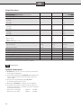
Specifications
DH18100 DH21100 DH24100
Rated power [kW]
18 21 24
Rated voltage
400 V 3 ~ 400 V 3 ~ 400 V 3 ~
Heating capacity – economy setting e [kW]
–
1st stage 6 7 8
2nd stage 12 14 16
Heating capacity – intensive setting II [kW]
1st stage 9 10.5 12
2nd stage 18 21 24
Switch-on point [I/min]
1st stage 4.0 4.5 5.0
2nd stage 5.0 5.8 6.6
Mixed water [I/min] at rated power
approx. 38 °C 9.8 11.5 13.1
approx. 50 °C
(supply temperature 12 °C)
6.7 7.8 9.0
Minimum flow pressure of appliance* [MPa (bar)]
with flow limiter 0.6 (6) 0.8 (8) 0.9 (9)
without flow limiter 0.4 (4) 0.5 (5) 0.6 (6)
Energy efficiency class
BBB
Load profile
SSS
Annual energy consumption [kWh]
495 497 501
Daily energy consumption [kWh]
2.301 2.313 2.337
Sound power level [dB]
15 15 15
Hot water heating energy efficiency [%]
37.2 37.1 36.8
* The pressure loss on the mixer must also be added.
VII.
Dimensions
Special accessories
■ BZ 45K24 Pipe set: for use of the continuous-flow heater
as an under sink appliance
■ Intermediate terminal block BZ 45Z20: Required when the
mains connecting cable is fed in through the bottom ac-
cess hole 14a.
■ Priority switch (load shedding relay) BZ 45L21:
for operation with a priority circuit
■ Mounting kit BZ 45K24: for surface mount installation
■ Truncated connecting piece sealed at rear for water con-
nection from below (e. g. cold water connection via fitting
mounted below heater):
Elbow joint, “cold” (right) Order no. 056169
Elbow joint, “hot”, (left) Order no. 255568

13
en
Operating instructions
Please read and observe the detailed safety instructions
at the start of these instructions!
■ Important: The appliance may never be exposed to frost!
Risk of electric shock!
Switch off the mains voltage supply immediately if
a fault occurs.
■ Immediately shut off the cold water supply to the appli-
ance should it leak.
Getting to know your appliance
The continuous-flow heater heats the water as it flows
through the appliance. The appliance only consumes power
during this period.
This appliance can supply hot water to taps in several dif-
ferent locations. It should be installed close to the tap that
is used the most frequently. This will enable you to reduce
energy consumption.
Operating the appliance
The continuous-flow heater has two power settings:
e Economy setting – two thirds power
II Intensive setting – full power
automatic
e
The e setting is ideal for:
Wash basin
Shower
Bidet
II setting should be used where a higher temperature or a
larger volume of water is required, e. g.
Dishwashing
Cleaning
Bath tub
If you are using a thermostat-controlled mixer tap, set the
heater to II.
1. Set the heater to either e or II, as required.
2. Turn on the hot-water tap.
The continuous-flow heater switches on automatically and
heats the water as it flows through the appliance.
The heater switches off again when you turn off the tap.
Increasing the water temperature
When the tap is turned on fully, it is possible that the heater
capacity is not sufficient to heat the water to the required
temperature.
■ Slightly close the hot-water tap. The water flows through
the appliance more slowly and reaches a higher tempera-
ture as a result.
Decreasing the water temperature
■ Mix with cold water.
Note about operation
When a hot-water tap is turned on by only a small amount,
the continuous-flow heater operates at half power regardless
of which setting (e, II) has been selected.
When a hot-water tap is turned on fully, the appliance oper-
ates at the maximum level of power that corresponds to
whichever setting has been selected.
Saving energy
■ Please use economy setting “e” as often as possible.
To minimise energy consumption when turning off the hot
water:
– Turn off the hot-water tap slowly in order to use the re-
sidual heat of the continuous-flow heater.
– This also prevents the water temperature from briefly
increasing above the preselected temperature if the hot-
water tap is turned on again within the next few minutes.
To obtain particularly uniform hot-water temperatures, it is
recommended to use thermostat-controlled mixer taps.
The thermostat-controlled mixer tap must be suitable for hy-
draulically controlled continuous-flow heater.
Winter operation
Note: It is possible in winter that the supply temperature of
the water is reduced and the required outlet temperature is
no longer achieved.
■ In order to compensate for this temperature reduction,
please reduce the water quantity on the tap until the re-
quired water temperature is achieved.
Cleaning
■ Simply wipe the appliance with a damp cloth.
Do not use acidic or abrasive cleaning materials.
Notes: It is normally not necessary to descale the appliance.
However, extremely hard water and the frequent flows of
very hot water can cause the appliance to scale up. In this
case please contact our after-sales service.

14
en
A fault, what to do?
Attention!
Repairs must only be carried out by an authorised
technician. Improper repairs can lead to risk of seri-
ous injury to the user.
If your appliance does not operate as required, it is often
due to a very minor problem. Please check whether you can
remedy the fault yourself by using the following guidelines.
You will save yourself the costs of an unnecessary visit by
customer service personnel.
The water does not heat up or not enough water flows
out of the tap:
■ Check the fuse in the fusebox.
■ Drop in pressure in the water mains. If the pressure is too
low, the appliance will not switch on.
■ The strainer on the tap or shower head is blocked.
Unscrew the strainer and either clean or descale it.
■ The corner valve is clogged. Turn on the hot-water tap
fully and open and close the corner valve several times.
Then clean the filter in the water tap.
■ The heater needs descaling. Arrange for a service engi-
neer to visit.
The continuous-flow heater switches off during the
drawing-off of water, resulting in a reduction in the
water temperature:
■ The washer inside the hot-water tap must be a non-swell-
ing type.
If you cannot resolve the problem yourself, switch off the
heater via the fuse in the domestic wiring. Arrange for a
service engineer to visit.
After-sales service
If you call the after-sales service for assistance, please specify
the E no. and FD no. of your appliance.
These numbers can be found on the underside of the contin-
uous-flow heater.
Disposal
This appliance is labelled in accordance with Euro-
pean Directive 2012/19/EU concerning used elec-
trical and electronic appliances (waste electrical
and electronic equipment – WEEE).
The guideline determines the framework for the
return and recycling of used appliances as appli-
cable throughout the EU.
Please ask your specialist retailer about current
disposal facilities.
Guarantee
The guarantee conditions for this appliance are as defined by
our representative in the country in which it is sold.
Details regarding these conditions can be obtained from the
dealer from whom the appliance was purchased. The bill of
sale or receipt must be produced when making any claim
under the terms of this guarantee.
Subject to change without notice.


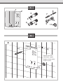
I.
9
8
11
7
10
3
4
5
6
12
Montageschablone Mounting template
Montagesjabloon Szablon montażowy
Gabarit de montage
14
14a
13
14a
3
2
1
14a
automatic
e
12
12
14a
14
14a
14a
12
Kaltwasserzulauf
cold water supply
dopływ zimnej wody
soğuk su giriși
3
II.
A

II.
Warmwasser
warm water
ciepłej wody
sıcak su
Kaltwasser
cold water
zimnej wody
soğuk su
2.
1.
B
C

II.
98
11
9
8
11
Variabler Wandabstand
adjusting distance from wall
zmiana odległości od ściany
değișken duvar mesafesi
0
–25 mm
0
–25 mm
E
D

90
–120 mm
±10
15
„kalt“
“cold”
„zimnej“
“soğuk”
„warm“
“hot”
„ciepły“
“sıcak”
III.
IV.
A14 a A
1
3
5
L2
L3
L1
L1
L2
L3
14 a
18 kW 21 kW/24 kW

V.
automatic
e
e e
oder
or
dnie
veya
1.
2.
3.
Strona się ładuje...
Strona się ładuje...
Strona się ładuje...
Strona się ładuje...
Strona się ładuje...
Strona się ładuje...
Strona się ładuje...
Strona się ładuje...
Strona się ładuje...
Strona się ładuje...
Strona się ładuje...
Strona się ładuje...
Strona się ładuje...
Strona się ładuje...
Strona się ładuje...
Strona się ładuje...
-
 1
1
-
 2
2
-
 3
3
-
 4
4
-
 5
5
-
 6
6
-
 7
7
-
 8
8
-
 9
9
-
 10
10
-
 11
11
-
 12
12
-
 13
13
-
 14
14
-
 15
15
-
 16
16
-
 17
17
-
 18
18
-
 19
19
-
 20
20
-
 21
21
-
 22
22
-
 23
23
-
 24
24
-
 25
25
-
 26
26
-
 27
27
-
 28
28
-
 29
29
-
 30
30
-
 31
31
-
 32
32
-
 33
33
-
 34
34
-
 35
35
-
 36
36


Siemens DH18100 Instrukcja obsługi
- Typ
- Instrukcja obsługi
w innych językach
- Deutsch: Siemens DH18100 Benutzerhandbuch
- Türkçe: Siemens DH18100 Kullanım kılavuzu
- English: Siemens DH18100 User manual
Powiązane artykuły
-
Siemens DH40021 Instrukcja obsługi
-
Siemens DH40024M Instrukcja obsługi
-
-
-
-
Siemens DE21401 Instrukcja obsługi
-
-
-
-