
2x click
2x click
P.P.H.U. AWEX
Ul.Długa 39 Masłomiąca
32-091 Michałowice
tel:+48 12 681 55 00
fax:+48 12 681 55 22
www.awex.eu
INSTRUKCJA MONTAŻU
OGÓLNE WARUNKI GWARANCJI dostępne są na stronie internetowej producenta www.awex.eu
Zamówiony towar wyprodukowany wg indywidualnego zamówienia odbiegający od standardowej oferty firmy Awex nie podlega zwrotowi.
SPECYFIKACJA TECHNICZNA:
- Napięcie zasilania: 220 - 240VAC/50 - 60Hz, 176 - 275VDC, 24VDC
- Klasa izolacji: II lub III
- Stopień ochrony: IP44
- Czas pracy w trybie awaryjnym: 1, 2 lub 3h
- Źródło światła:1W, 2W lub 3x1W LED
- Czas ładowania akumulatora: maksymalnie do 24h
- Temperatura otoczenia: 0 - +40°C
- Odległość rozpoznawania: 25m
CECHY CHARAKTERYSTYCZNE:
- Sygnalizacja ładowania akumulatora za pomocą diody LED
- Elektroniczne zabezpieczenie przed rozładowaniem baterii
- Funkcja automatycznego testowania (opcjonalnie)
- Możliwość pracy w trybie awaryjnym lub sieciowo - awaryjnym
- Możliwość zastosowania do systemu monitorowania Rubic
- Możliwość zastosowania do centralnej baterii
- Montaż podtynkowy do sufitu
- Korpus oprawy wykonany z poliwęglanu, szyba z plexi
- Oprawa może być zasilana ciągle lub nieciągle
- Montaż do powierzchni płaskich wewnątrz budynku
- Oprawa jest wyposażona w moduł, który pozwala zmieniać
tryb pracy na awaryjny
ZALECENIA UŻYTKOWE:
Aby zapewnić prawidłową i bezawaryjną prace oprawy należy przestrzegać
następujących zasad:
- Pakiety akumulatorów muszą współpracować z modułami awaryjnymi
- Instalację oprawy powinna wykonywać odpowiednia osoba, do takich
czynności uprawniona
- Po zainstalowaniu oprawy powinno nastąpić formatowanie akumulatora
poprzez ciągle ładowanie w okresie 24h i pełne rozładowanie świeceniem
- Należy przeprowadzić trzy pełne cykle formatowania aby uzyskać jak
największą pojemność akumulatora
- Raz w roku nalezy przeprowadzić przegląd techniczny oprawy a zwłaszcza
akumulatora
- Ważne jest zachowanie parametrów temperaturowych dla pakietów
bateryjnych tj. od 0°C do +55°C
- Zabrania sie jakichkolwiek zmian w konstrukcji układu. elektronicznego
- W przypadku gdy oprawa nie zapewnia podtrzymania zasilania dla
znamionowego czasu pracy, nalezy wymienić akumulator
- Producent zaleca wymianę akumulatora co 4 lata
- Oprawa jest wyposażona w wymienialne źródło światła
- Znamionowy strumień światła w trybie awaryjnym wynosi 100%.
WARUNKI GWARANCJI:
Warunkiem uznania gwarancji jest:
- Brak uszkodzeń mechanicznych
- Brak śladów ingerencji osób trzecich w konstrukcję oprawy a zwłaszcza
modułu awaryjnego
- Prawidłowa eksploatacja zgodna z zaleceniami
- Prawidłowe podłączenie napięcia zasilającego i pakietu akumulatorowego
(UWAGA!, nalezy zwrócić uwagę na biegunowość zacisków baterii i
przetwornicy).
TESTOWANIE OPRAWY:
Istnieje możliwość testowania oprawy za pomocą przycisku testu
umieszczonego w obudowie (opcjonalnie). W momencie podłączenia
oprawy do napięcia zasilającego zapala się zielona dioda sygnalizująca
pojawienie się napięcia w układzie elektronicznym a tym samym ładowanie
akumulatora. Wciśniecie przycisku powoduje aktywacje testu oprawy poprzez
przerwę w obwodzie a tym samym symulację zaniku napięcia sieciowego i
przełączenie przez układ elektroniczny w tryb pracy awaryjnej. Podczas pracy
awaryjnej dioda LED przestaje świecić, oprawa jest zasilana z akumulatora. Po
zwolnieniu przycisku powraca napięcie sieciowe rozpoczyna się proces
ładowania.
FUNKCJA AUTOTEST:
Test A wyzwalany jest automatycznie co 28 dni. Podczas wykonywania
testu A sprawdzane są następujące parametry: wymuszenie pracy awaryjnej oprawy
na czas 1 min. Kontrola prądu rozładowania akumulatora.
Test B wyzwalany jest automatycznie co 364 dni.Podczas wykonywania
testu B sprawdzane są następujące parametry: wymuszenie pracy awaryjnej oprawy
na czas zdeklarowany dla danej oprawy, kontrola prądu rozładowania akumulatora,
kontrola napięcie akumulatora.
TECHNICAL SPECIFICATION
- Supply voltage: 220 - 240VAC/50 - 60Hz, 176 - 275VDC, 24VDC
- Insulation class: II or III
- Protection level: IP44
- Time of operation in emergency mode : 1, 2 or 3h
- Light source:1W, 2W or 3x1W LED
- Battery charging time : up to 24h
- Ambient temperature : 0 - +40°C
- Viewing distance: 25m
MAIN FEATURES:
- Battery charging indication by LED
- Electronic protection against total battery discharge
- Self-test function (optional)
- Operation in emergency or mains and emergency mode available
- Using to Rubic system available
- Using to central battery available
- Recessed (ceiling) assembly
- Assembly indoors to flat surface
- Polycarbonate body, plexi glass
- The luminaire can be powered maintained or non maintained
- Controlgear supplied within this luminaire performs the function of
changeover operation from normal to emergency mode
RECOMMENDATIONS FOR USE:
The following rules must be observed to ensure the correct and reliable
operation of the fitting:
- Battery packs must be compatible with emergency modules
- Installation of fitting should be made by appropriate person which is
authorized for such works
- After installation of fitting, the formatting of battery must be made while
continuous charging for a period of 24 hours and fully discharging it
through lighting
- Three full formatting cycles must be performed to achieve maximum
battery capacity
- Technical inspection of the fitting and, in particular, of the battery must
be performed once a year
- It is important to maintain temperature parameters for battery packs, i.e.
from 0°C to + 55°C
- It is forbidden to make any changes in electronic system design
- If the fitting does not withstand its rated operation time, the battery must
be renewed
- It is recommended by the manufacturer to renew the battery every 4 years
- The fitting is equipped with a replaceable light source
- Rated luminous flux in emergency mode amounts to 100%.
TERMS AND CONDITIONS OF WARRANTY:
The condition to acknowledge the warranty is:
- No mechanical damage
- No evidence of changes made by third party in fitting design and, in
particular, emergency module
- Proper use, as recommended
- Proper connection of supply voltage and battery pack (attention must be
paid to the polarity of the battery and converter terminals).
TESTING THE FITTING:
It is possible to test the fitting using test button placed in the housing (option).
At the time when the supply voltage is connected to the
fitting, the green LED lights up indicating the emergence of voltage in the
electronic system and thus the battery charging. By pressing the button,
the test of fitting is activated through an open circuit, and by this the
decay of mains voltage is simulated and the switching over by electronic
system to the emergency operation mode is caused. During emergency
operation, the LED is no longer lit, the fitting is powered from the battery.
When the button is released, the mains voltage returns and the fitting is
operated in mains mode, charging process is started.
AUTOTEST FUNCTION:
Test A is run automatically every 28 days. During test A a conversion kit
is switched to emergency mode for 1 minute and the following
parameters are checked: control of battery power discharge, control of battery.
Test B is run automatically every 364 days. During test B a conversion kit
is switched to emergency mode for all duration time and the following
parameters are checked: control of battery power discharge, control of
minimum battery voltage .
ASSEMBLY INSTRUCTIONS
GENERAL CONDITIONS OF WARRANTY are available on manufacturer's website at www.awex.eu
The goods ordered that were manufactured according to the individual order and differ from the standard offer of Awex may be not returned.
LED
24V
DC
Ni-Cd
Ni-MH
IP44
176-275V
DC
220-240V
AC
50-60Hz
d=25m
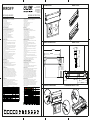
1
OPRAWA ARROW P ARROW P FITTING
2
WYMIARY OPRAWY ARROW P ARROW P FITTING
3
DEMONTAŻ OPRAWY ARROW P DISASSEMBLING ARROW P FITTING
A
B
ARROW P
LP. Źródło światła Opis
1 dowolny
Potwierdzenie resetu czasu lub
błędów (tylko AT)
2 świeci Praca awaryjna
3 nie świeci Tryb spoczynkowy
4 dowolny Błąd komunikacji (tylko RS)
5 dowolny Błąd akumulatora
6 dowolny Błąd źródła światła lub elektroniki
7 świeci
Wykonywany test lub praca
sieciowa
8 dowolny Brak akumulatora
9 nie świeci Ładowanie akumulatora
10 nie świeci Tryb gotowości (akumulator pełny)
11
nie świeci
Ustawiono za dużą moc wyjściową
w stosunku do pojemności
akumulatora
Czerwona dioda
Zielona dioda
Kolor świecenia LED
sygnalizacja błędów albo nie świeci
sygnalizacja błędów albo nie świeci
LP
Light
source
Description
1 any
Confirmation of the reset of
timer or errors (AT)
2
shining Emergency mode
3
not shining Standby mode
4
any Communication error (only RS)
5
any Battery error
6 any
Light source or electronics
error
7
shining Performing test or mains mode
8
any No battery
9
not shining Battery loading
10
not shining Standby mode (battery full)
11 not shining
Too much output power for this
battery capacity
Color of LED indicator shining
Error indication or not shining
Error indication or not shining
Red indicator
Green indicator
202 mm
206 mm
299 mm
230mm
20 mm
132mm
109mm
Ø19
Ø12
Ø43
130mm
206mm
43mm
327mm
130mm

WYMIARY OTWORU MONTAŻOWEGO
DIMENSION OF ASSEMBLY HOLE
300
45
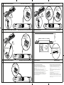
PODŁĄCZENIE ZASILANIA
POWER SUPPLY
220÷240VAC/50÷60Hz
N
L1
L
PODŁĄCZENIE ZASILANIA
POWER SUPPLY
220÷240VAC/50÷60Hz
N
L1
L
PODŁĄCZENIE KOMUNIKACJI
CONNECTION COMMUNICATIONS
B
A
N(-)
L(+)
PODŁĄCZENIE ZASILANIA
POWER SUPPLY
220÷240VAC/50÷60Hz
176÷275VDC
(-)
(+)
PODŁĄCZENIE ZASILANIA
POWER SUPPLY
24VDC
ZALECENIA PRODUCENTA DOTYCZĄCE MONTAŻU:
- w oprawie autonomicznej przewód L i L1 jest wymagany dla trybu
dwuzadaniowego (SA), dla jednozadaniowego (SE), nie jest wymagany L1
- podczas podłączania baterii zwrócić szczególna uwagę na prawidłową
polaryzację „+” i „-”
- podczas podłączania przewodów komunikacyjnych zaizolować ekran, który
może prowadzić do zwarcia pozostałych żył komunikacyjnych
- najpierw należy podłączyć do modułu baterie a następnie podłączyć zasilanie sieciowe
- adres oprawy CBS nie może być zdublowany w obrębie jednego obwodu
- podłączając oprawę do systemu FZLV zachować polaryzację „+” , „-”
- rysunki zamieszczone w instrukcji mogą nieznacznie różnić się od wyrobów
gotowych, w celu poprawnego podłączenia należy postępować zgodnie z
naklejką umieszczoną na oprawie.
PRODUCER’S GUIDLINES RELATED TO INSTALLATION PROCEDURE:
- in a fitting the cable L and L1 is required to the maintained mode (SA)
,the non maintained mode (SE) does not require L1 cable
- during the battery connection, pay attantion to proper polarisation
„+” and „-”
- during the communication cables connection, pay attantion to isolation of
the cable’s shield which can lead to a short circut of the others
communication lines
- The first if all you have to connect battery to inverter and then
connect the mains supply
- CBS fiting address cannot be doubled in a single circut
- during connection to the FZLV system, keep the proper polarisation„+” , „-”
- the drawing enclosed in this instruction may be vary than in the finished
products, to a proper connection follow the instruction enclosed in the label
attached on a fitting
PODŁĄCZENIE BATERII
CONNECTION BATTERY
!
KONFIGURACJA ADRESU
ADDRESS CONFIGURATION
4
PODŁĄCZENIE OPRAWY DO SYSTEMU RUBIC
CONNECTION OF FITTING TO RUBIC SYSTEM
4a
MONTAŻ OPRAWY DO SUFITU SURFACE ASSEMBLY
ZALECENIA PRODUCENTA PRODUCER’S GUIDLINES
6
4c
5
PODŁĄCZENIE OPRAWY AUTONOMICZNEJ
CONNECTION OF AUTONOMOUS FITTING
PODŁĄCZENIE I USTAWIENIE OPRAWY DO SYSTEMU CBS
CONNECTION AND SETUP OF FITTING TO CENTRAL BATTERY
4b
PODŁĄCZENIE OPRAWY DO SYSTEMU FZLV CONNECTION OF FITTING TO FZLV CENTRAL BATTERY
!
PODŁĄCZENIE BATERII
CONNECTION BATTERY
!
min
150mm
-
 1
1
-
 2
2


