
Technical manual
Livret technique
Technisch boek
Техническое руководство
Instrukcja techniczna
EN
NL
RU
MARK EASYAIR
0662600_R04
PL
FR

2

EN
3
Read this document before
installing the appliance
Warning
An incorrectly performed installation, adjustment, alteration, repair or maintenance
activity may lead to material damage, injury or explosion. All work must be carried out by
approved, qualied professionals. If the appliance is not positioned in accordance with the
instructions, the warranty shall be voided.
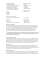
If the manual refers to an image or table, a number will be shown between square brackets, for
example [3]. The number refers to images and tables at the back of the manual with the stated
number.
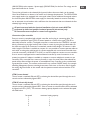
General
Every Mark air curtain is manufactured conforming to European directives and the latest
standards. To ensure quality and maximum reliability, each air curtain is inspected and tested
prior to leaving the factory, this guarantees a nal product of high quality with a long lifespan.
Mark air curtains are manufactured with warm water heaters or electrical heaters.
Conditions to obtain optimum performance of the air curtain
The room temperature must be +4°C minimum and +40°C maximum.
The outlet temperature has a maximum of +55°C.
Upon receipt open the transit packaging and inspect the unit to ensure that no damage has
occurred during transport. Any visible damage must be reported to your Mark distributor
immediately and prior to installation. Do NOT open the packing if transit damage is visible.
Store the unit under cover and protected from physical damage, dust, frost and rain.
Storage temperatures must be between –20°C en +40°C.
Take care that the unit will not be damaged when transporting the unit.
Attention! Heavy load.
Do not step under hanging load during transport or installation.
Installation
For best results and efciency install the air curtain close to the upper edge of the door opening
as possible. Make sure to maintain easy access to the air curtain access-hatch, especially for
series Effect BP. The air curtain can be installed using threaded rods M8 (type S, M and L)
or M12 (type LX). The air curtain has threaded holes M8 (type S, M and L) or M12 (type LX)
on top. If the air curtain is for false ceiling installation, the suction box also contains threaded
holes of the same size. A separate sketch with measurements is available on request. Make sure
the mounting construction is capable of supporting the weight of the air curtain. See also the
chapter ‘Installation examples’ further on this manual.
!

4
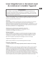
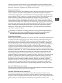
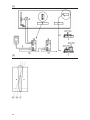
Installation examples [1] Mounting examples [2]
1 Free hanging installation 1 Rawl bolt
2 Installation in front of automatic doors 2 Anti-vibration mount
3 Installation using wall brackets 3 Turnbuckle
4 Installation ush with ceiling 4 Threaded rod
5 Installation within the ceiling void 5 Tapping in appliance
6 Installation inside a draught lock
A Ceiling mounted
A Inlet B Wall mounting
B Outlet
C Outside
D Inside
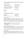
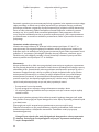
Connections to upper side [3]
A Optional solenoid valve 230V/50Hz F To controller
B Controls G To air-curtain 2
C Power H To air-curtain 3
D Air-curtain 1 I Type II (water)
E Optional air-curtain 2 and following J Type IIE (electrical)
Feed water connections
The air curtain is equipped with a water supply pipe connection (IN) and a water return pipe
connection (OUT) on the left top of the unit. The sizes for water connection range between
½” and 1½” (inner thread), depending on the heating performance of the unit. A drain valve is
located at the bottom of the heat exchanger and is accessible through the service hatch.
Two shut-off valves should be installed to allow trouble-free dismantling of the air curtain.
An (automatic) aeration valve should be installed at the highest point of the pipe work.
Attention! All installation work must comply with local regulations. All work concerned
with the electrical installation of the air curtain MUST only be performed by skilled
and qualied technical personnel.
Outlet temperature control
The outlet temperature of the air curtain can be adjusted to a consist level by using an optional
thermostatic (three way) valve. The valve has to be mounted in the water supply pipe. The sensor
needs to be mounted on the fan at the left hand side by using the pre mounted sensor support.
Use the perforation at the top left side of the unit to lead the sensor inside the unit (remove the
cap). See also the information provided with the thermostatic valve for more details.
Solenoid valve
The air curtain is equipped for the use of an optional solenoid valve 230VAC/50Hz to shut
the water supply off during summer time. The solenoid valve is electrically connected on the
terminal block at the top side of the unit. The terminal block is positioned next to the controller
terminal block, see the wiring diagrams further on this manual for details.
Electrical connections
The standard position of the terminal block to connect the electrical power supply is located
at the right hand top side of the air curtain. Every connection must be made according to the
wiring diagram. Keep in mind that an electrically heated air curtain needs a 3 phase power supply
!

(400VAC/50Hz) and a separate 1 phase supply (230VAC/50Hz) for the fans! For ratings see the
type shield inside the air curtain.
The air inlet grill needs to be released (click system) before the access hatch can be opened.
Use a at screwdriver to release it, be careful not to damage the paintwork. The 230VAC/50Hz
main supply needs to be equipped with a two-pole isolator and an additional three-pole isolator
for the three-phase 400VAC/50Hz main supply for electrically heated air curtains. Preferably
use an automatic circuit breaker with a sufcient slow characteristic that can withstand the fans
relatively high running current.
All work concerned with the electrical installation of the air curtain MUST be
performed by skilled and qualied technical personnel (electricians) only.
All connections must conform to current local regulations.
Connection of the controller
Every air curtain is completed with a digital controller and its plug in connecting cable. The
controller is specied as type GTM II for water heated air curtains and as type GTM IIE for
electrically heated air curtains. The digital controller is connected at the ‘CONTROL’ terminal
block, positioned on the right hand top side of the air curtain, by using the provided cable. On
the cable two male RJ-45 connectors are attached, standard cable length is 20 meters. A cable
with a length of 50 meters is available on request. It is not possible to connect separate cables to
each other to enlarge the cable length. Air curtains equipped with a triac-based controller have
a second connection (‘AUXILIARY’ of ‘AUX’) to connect multiple air curtains on one controller.
If an air curtain is equipped with a transformerbased controller (a second connection is not
present) an optional Y-adapter is available on request to connect multiple air curtains on one
controller. Every controller has a memory function, in case of a power failure the selected fan
speed will be returned after the power is re-established. Every controller is also provided with
a potential free contact. This contact can be used for any remote ON/OFF device, for example
a Building Management System, switching thermostat, clock timer or re alarm. See for details
the wiring diagrams further in this manual and the operation manual enclosed with the GTM
controller.
GTM II, water heated
The air curtain is switched ON and OFF by selecting the desired fan speed through the touch
controls and are indicated by lighted LED’s.
GTM IIE, electrically heated
The air curtain is switched ON and OFF by selecting the desired fan speed through the touch
controls and are indicated by lighted LED’s. If the air curtain is switched off this will be indicated
by lighted red LED’s (‘OFF’). The maximum heating capacity depends on the selected fan speed,
see table below:
fan speed maximum heating capacity
1 1
2 1
3 2
4 3
5 3
EN
5
!

6
The controller is equipped with an automatic after run function that assures the removal of any
heat remaining due to thermal inertia after switching off the air curtain. If the air curtain reaches
an abnormal high temperature (for example due to dust accumulation on the inlet grill) the fan
speed will be increased and the heating capacity decreased. In this situation the controller will
show ashing LED’s. When the temperature is normal all settings will return to their original
selected positions. If the air curtain is installed in a relatively small space then a room thermostat
is recommended.
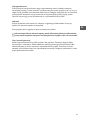
Positioning the outlet vanes [4]
The vane’s can be adjusted in an inwards or outwards angle of 10° or 15° and in the vertical
position. For the best results the vane’s should be adjusted in a outwards position during
wintertime and in a inwards position during summertime in combination with an air
conditioned environment. It is recommended to adjust the vane in the 10° outward position
when the distance between the air curtain and the door is 30 cm or less. When the distance
between the air curtain and the door is more than 30 cm, it is recommended to adjust the
vane in the 15° outward position.
Maintenance
An Mark air curtain does not need any kind of maintenance except regular cleaning. No
dismantling is needed for cleaning. The inlet grill with micro holes acts as an lter as well. Check
the inlet lter grill for obstructions and clean if necessary. The check period may be weekly (for
high people trafc and high air pollution) or till monthly (for low people trafc and moderate
air pollution). In air conditioned environments a monthly check should be adequate but more
regular checks should be made immediately following installation. Clean the inlet grill with one of
the following methods:
– Wipe off dust with a dry cloth.
– Vacuum off dust using a dry vacuum cleaner with a brush attachment.
– Where the dust build up is very thick it may be necessary to use a soft brush.
Clean the casing by using a slightly moist cloth and a mild cleaning detergent is necessary.
Never use any scratching, etching or acid detergents.
Never clean the air curtains interior with water or steam.
The recommended maintenance must be carried out as neglect may result in air starvation and
strain the fans. Neglect may invalidate the warranty!
Attention! Only use water or non-aggressive detergents to clean the casing.
Never use liquids or steam for cleaning internal parts and components.
In case of failure
Clean the inlet grill of any dust build up (see Maintenance above). Check if the hot water
system is on and the piping is warm. Check the condition of the circuit breakers. Set the air
curtain in the highest fan position by pressing the buttons on the controller. Contact your Mark
representative if the above did not help.
!

Repair
The air curtain must always be switched off from the main electrical supply. Make sure that the
fans have come to al full stop.
Only use genuine Mark spare-parts!
In case of a repair always bring the fans to a full stop by using the controller
before disconnecting the main electrical supply!
Terms of guarantee
Every Mark air curtain has a 2 years period of guarantee. Guarantee is applicable on
construction- and material errors. Before a claim for guarantee written conversation needs to
be made with your Mark representative in advance. Guarantee may not be applicable when lag of
maintenance is observed. All this is under reservation and review of your Mark representative.
EN
7
!

8
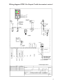
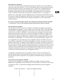
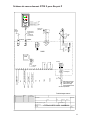
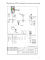
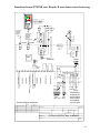
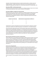
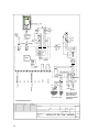
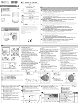
Wiring diagram GTM II for Easyair P with doorcontact control
230V/ 50Hz
3
CONTROL
F 16 AT
LNPE
PCB EC
Connecting box
Mains switch and fuses
to be installed by third
parties must comply
to all applicable ruls and
requirements!
Technical changes reserved
1211 12 1334 514 15
0
to input
CONTROL
next PCB
8
AUXILIAR
NL2
PE
230V / 50Hz
Magnetic valve
(OPTIONAL)
L PEN
8
PE
NL2
intern
AUX MON
01.08.2014
la
gezeichnet/signet
Teile
Gruppe
vonPos.
Werkstoff
Maßstab
Blatt
Erstelldatum
GTM II EC UK 140801
Kunde
Benennung
Name
Kundenzeichnung Nr.:
DatumName
1 von 1
6716 17 8 9 10 1918 20
CPU
Adress
switch
0 = MASTER
1 - 9 = SLAVE
5
1
2
3
4
9
8
7
6
ext. Contact
BMS On/Off
Failure
Operation
Frost protection thermostat
free
free
free
optional
optional
Standard supplied
shielded datacable
(20 m)
1:1 straight wired
RJ 45 connentors!
1
M
PE
N
L1
next
Fan
blau/blue
gelb/yellow
weiss/white
rot/red
4
Room Thermostat
optional
ext. Contact
Roomm Thermostat
3
1
4
2
optional
optional
Hand
Stufe
MODE
Y 0-10 V
0 V
+10 V
imp.
Fr 01.08.14 - 11.55

9
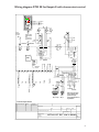
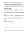
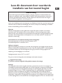
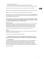
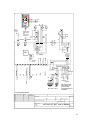
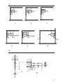
Wiring diagram GTM IIE for Easyair E with doorcontact control
CONTROL
PCB EC
Technical changes reserved
1211 12 1334 514 15
0
to input
CONTROL
next PCB
8
AUXILIAR
8
AUX MON
01.08.2014
la
gezeichnet/signet
Teile
Gruppe
vonPos.
Werkstoff
Maßstab
Blatt
Erstelldatum
GTM II E EC UK 140801
Kunde
Benennung
Name
Kundenzeichnung Nr.:
DatumName
1 von 1
6716 17
8 9 10 1918 20
CPU
Adress
switch
0 = MASTER
1 - 9 = SLAVE
5
1
2
3
4
9
8
7
6
ext. Contact
BMS On/Off
Temperature sensor
q
Failure
Operation
free
free
free
optional
Standard supplied
shielded datacabl
(20 m)
1:1 straight wired
RJ-45 connectors
S 50°
K1
K1
K2 K3
S 80°
S 60°
q
q
q
q
K1
free
Connecting box
Mains switch and fuses
to be installed by third
parties must coply
to all applicable rules and
requirements!
1
M
PE
N
L1
next
Fan
blau/blue
gelb/yellow
weiss/white
rot/red
4
step 2
step 3 = step 1 + step 2
step 1
NL2
PE
PE
NL2
intern
230V / 50Hz
L N PE312
F 16 AT
K2K3
4
3~400V/ 50Hz
3
230V/ 50Hz
K0
q
q
ext. Contact
Temperature sensor
3
1
4
2
optional
optional
S 45°
Y 0-10 V
0 V
+10 V
imp.
S 100°
AutoTA 20°C
AKS
15°C
MODE
Fr 01.08.14 - 11.55

10

Lisez intégralement ce document avant
de commencer à installer l’appareil
Avertissement
Une installation, un paramétrage, une modication ou un entretien mal effectué peut
provoquer des dommages matériels, des blessures ou une explosion. Toutes les activités
doivent être réalisées par des professionnels qualiés agréés. Si l’appareil n’est pas installé
selon les prescriptions, la garantie échoit.
Lorsque le mode d’emploi renvoie à une image ou à un tableau, il mentionne un nombre entre
crochets, par exemple [3]. Le nombre renvoie à des images et des tableaux à la n du mode
d’emploi, qui portent le nombre mentionné.
Généralités
Tous les rideaux d’air Mark sont fabriqués selon les directives européennes et les dernières
exigences techniques. Le contrôle de qualité comprend des tests du matériel et du
fonctionnement pendant chaque étape du processus de production ; un produit nal de qualité
supérieure et de longue durée de vie est ainsi garanti. Les rideaux d’air Mark sont livrés pour
l’eau chaude (norme 60/40 °C) ou chauffage électrique.
Conditions pour un fonctionnement optimal d’un rideau d’air
La température ambiante est de minimum + 4 °C et maximum + 40 °C.
La température de soufage est de maximum + 55 ° C.
Stockage et transport
Ouvrez l’emballage lors de la réception et contrôlez les éventuels dommages de transport
du rideau d’air. Les dommages visibles doivent être immédiatement signalés. N’ouvrez PAS
l’emballage si des dommages sont visibles de l’extérieur. Stockez le rideau d’air au sec et
laissez-le aussi longtemps que possible dans l’emballage pour éviter les dommages.
Température de stockage entre -20 °C et + 40 ° C.
Veillez à ce que le rideau d’air ne soit pas endommagé pendant le transport.
Attention ! Charge lourde.
Ne pas vous placer sous la charge suspendue pendant le transport ou le montage.
Montage
Le rideau d’air doit être monté le plus près possible de la porte. Veillez à ce que le couvercle
de révision reste en permanence accessible, même si le rideau d’air est réalisé comme BP
(adapté pour le montage au-dessus d’un plafond abaissé). Le montage du rideau d’air se fait à
l’aide de tiges letées M8 (types S, M et L) ou tiges letées M12 (type LX), raccords de serrage,
amortisseurs antivibratoires, écrous coulissant et prols Flamco au plafond. Les points de
suspension du rideau d’air sont dotés d’usine d’écrous M8 (types S, M et G) ou M12 (type LX).
Si le rideau d’air est réalisé comme montage au même niveau que le plafond ou comme montage
au-dessus du plafond, des points de suspension supplémentaires sont prévus dans la partie
FR
11
!

supérieure du bac d’aspiration. Pour les dimensions exactes, voir la che de mesure adaptée
(disponible sur demande). Lors de la sélection et de l’application du matériel de montage, tenez
compte du poids du rideau d’air !
Exemples d’application [1] Exemples de suspension [2]
1 Montage à suspension libre 1 Goujon de béton
2 Montage devant un automate de porte 2 Amortisseur antivibratoire
3 Montage avec consoles murales 3 Raccord de serrage
4 Montage de niveau avec le plafond (GP) 4 Tige letée M8
5 Montage au-dessus du plafond (BP) 5 Écrou intégré M8
6 Application dans sas d’aspiration
A Montage au plafond
A Aspiration B Montage mural
B Pulsion
C Extérieur
D Intérieur
Position raccordements partie supérieure [3]
A Soupape magnétique facultative 230V/50 Hz F Vers le régulateur
B Commande G Vers le rideau d’air 2
C Alimentation H Vers le rideau d’air 3
D Rideau d’air 1 I Type II (eau)
E Éventuellement rideau d’air 2 et suivants J Type IIE (électrique)
Raccordements côté eau
Les raccords d’alimentation (IN) et de retour (OUT) de l’échangeur de chaleur se trouvent
d’origine du côté gauche au-dessus du rideau d’air et sont réalisés selon le type ½” à 1½”
(letage intérieur). L’échangeur de chaleur est doté sur le dessous d’un mamelon de vidange.
L’échangeur de chaleur standard est adapté pour les systèmes à basse température de 60/40 °C.
Montez les robinets tant sur la conduite d’alimentation que de retour le plus près possible du
rideau d’air et une soupape de désaérage (automatique) au point le plus haut des conduites.
Attention ! Toutes les activités doivent répondre à la législation et aux
règlementations locales.
Tous les raccords électriques doivent être réalisés par du personnel f
ormé et qualié.
Régulation de la température de soufage
A l’aide d’une soupape (à trois voies) thermostatique en option, la température de soufage est
maintenue constante. La soupape est montée dans la conduite d’alimentation du rideau d’air.
Le capteur est xé au ventilateur de gauche à l’aide d’une bride de xation prémontée. Utilisez
pour le passage du capteur l’encoche en haut à gauche sur le rideau d’air (retirer le bouchon
obturateur). Pour plus d’information, voyez les directives d’utilisation de la soupape.
Soupape magnétique
Il est possible d’utiliser une soupape magnétique facultative 230V/50 Hz pour couper l’arrivée
d’eau chaude par exemple pendant l’été (uniquement pour le modèle à eau). La soupape est
raccordée sur le montage sur borne au dessus du rideau d’air. Ce raccordement se trouve près
du connecteur auquel le câble du régulateur est raccordé, les schémas se trouvent plus loin dans
ce manuel.
12
!

Raccordements électriques
La boîte de raccordement pour l’alimentation électrique du rideau d’air se trouve standard du
côté droit au-dessus du rideau d’air. Tous les raccordements selon le schéma annexé. Attention
que deux alimentations séparés sont nécessaires pour un rideau d’air à chauffage électrique !
Voir pour le facteur de raccordement la plaque type à l’intérieur du couvercle de révision.
En libérant la grille d’aspiration de son encadrement, il est possible d’ouvrir le couvercle de
révision à l’aide d’un tournevis plat. Prévoyez pour l’alimentation 230 V un commutateur
bipolaire et un commutateur tripolaire supplémentaire pour l’alimentation 400 V/50Hz s’il s’agit
d’une version chauffée électriquement. Utilisez pour la sécurisation du rideau d’air de préférence
un fusible avec un caractère sufsamment long (caractéristique) lié à un ux de démarrage
relativement élevé.
Tous les raccords électriques doivent être réalisés par du personnel formé et qualié
(électriciens). Tous les raccordements doivent répondre aux normes en vigueur.
Raccordement du régulateur
Tous les rideaux d’air sont livrés avec un régulateur numérique et un câble de raccordement.
Type d’indication du régulateur en cas de modèle à eau chaude Type GTM II, modèle électrique
Type GTM IIE. Le régulateur numérique du rideau d’air est raccordé au dessus du rideau d’air
raccordé sur le raccord « CONTROL » à l’aide du câble de raccordement. Ce câble est doté
de deux connecteurs RJ-45 et fait 20 cm de long. Sur demande, un câble d’une longueur de 50
mètres peut être obtenu. L’allongement par un second câble de raccordement standard n’est
pas possible. Les rideaux d’air disposant d’un régulateur triac sont également dotés d’un second
raccordement (« AUXILIARY » ou « AUX ») pour le raccordement de plusieurs rideaux d’air
sur un régulateur. Pour les rideaux d’air avec un régulateur trafo qui sont dotés d’un second
raccordement, un adaptateur Y facultatif est disponible pour pouvoir raccorder de cette manière
plusieurs rideaux d’air à un régulateur. Chaque régulateur est équipé d’une fonction mémoire
qui assure que le rideau d’air soit de nouveau en état de revenir dans la position réglée lors de la
chute de la tension. Chaque régulateur est également équipé d’un contact de mise en service. Ce
contact peut être commandé par un système de gestion d’immeubles, thermostat, minuterie ou
installation de notication d’incendie. Voir également les divers schémas de raccordement dans
ce manuel et le manuel d’utilisation joint à la régulateur de GTM.
Un régulateur manuel/automatique est disponible en option avec des raccordements pour
un thermostat d’ambiance et un thermostat de sécurité contre le gel et un contact de porte.
Pour plus d’information et l’application de ce régulateur manuel/automatique, contactez votre
fournisseur.
Fonctionnement du régulateur GTM IIE
Les positions de chauffage et de ventilation souhaitées sont réglées à l’aide des touches à
efeurement et représentés par des LED allumés. Si le rideau d’air est débranché, les LED rouge
sont allumés (« OFF »). La capacité de chauffage maximale dépend de la position réglée du
ventilateur :
Position du ventilateur Capacité de chauffage maximale
1 1
2 1
3 2
4 3
5 3
FR
13
!

Le régulateur dispose d’une fonction d’arrêt progressif qui veille à ce que la chaleur résiduelle
présente soit évacuée après la mise hors service du rideau d’air. Si le rideau d’air atteint une
température trop élevée pendant l’usage normal (par ex. parce que la grille d’aspiration est
polluée), le régime des ventilateurs est automatiquement relevé et la capacité de chauffage
est descendue jusqu’à ce que la température diminue sufsamment. Dans cette situation, les
positions activées par le régulateur sont afchées par des DEL clignotantes. Quand le rideau d’air
est sufsamment refroidi, l’appareil revient aux réglages programmés par l’utilisateur. Si le rideau
d’air est installé dans un espace relativement restreint, l’utilisation d’un thermostat d’ambiance
est recommandée.
Réglage des lamelles de soufage [4]
Pour un fonctionnement optimal du rideau d’air, il est important que les lamelles de soufage
soient quelque peu orientées vers l’extérieur. Les lamelles doivent être réglées au départ du
milieu tant vers l’extérieur que vers l’intérieur avec un angle de 10 ° à 15 °. Il est conseillé de
régler les lamelles de 10 ° vers l’extérieur si le rideau d’air est suspendu à moins de 30 cm de
la porte et de 15 ° si le rideau d’air est suspendu à plus de 30 cm de la porte. Si le rideau d’air
est également utilisé en combinaison avec le traitement de l’air, les lamelles de soufage peuvent
être tournées vers l’intérieur pendant l’été.
Entretien
Les rideaux d’air Mark ne demandent que peu d’entretien, un nettoyage régulier de la grille
d’aspiration suft. Pour le nettoyage, le rideau d’air ne doit pas être ouvert. La grille d’aspiration
avec la perforation très ne fonctionne comme un ltre. Contrôlez si le ltre d’aspiration
n’est pas pollué et nettoyez-le si nécessaire. Contrôlez la grille d’aspiration chaque semaine
(fréquentation par beaucoup de personnes et/ou pollution forte de l’air) à chaque mois
(fréquentation par peu de personne et/ou pollution légère de l’air) Un contrôle plus fréquent
doit être réalisé directement après l’installation. Nettoyez la grille d’aspiration de la manière
suivante :
– Essuyez la poussière avec un chiffon sec, ou
– aspirez la poussière avec un aspirateur à brosse ;
– En présence de beaucoup de saletés, il peut être nécessaire d’utiliser une brosse douce pour
éliminer la poussière.
Nettoyez le boîtier avec un chiffon humide et éventuellement un détergeant doux. Ne jamais
utiliser des produits de nettoyage acides, mordants ou agressif.
Ne jamais nettoyer l’intérieur du rideau d’air avec de l’eau ou de la vapeur.
L’entretien recommandé doit être réalisé pour bloquer le courant d’air et éviter de cette
manière que les ventilateurs ne deviennent défectueux. La non exécution de l’entretien peut
faire échoir la garantie !
Attention ! Utilisez uniquement de l’eau ou des produits de nettoyage non agressifs.
N’utilisez jamais des liquides ou de la vapeur pour nettoyer les composants ou pièces
internes.
14
!

En cas de panne
Dépoussiérez la grille d’aspiration (voir entretien). Contrôlez ensuite si la chaudière cv est
lancée et si les conduites cv sont chaudes. Mettez le rideau d’air dans la position la plus élevée
avec le régulateur. Prenez contact avec votre installateur si les étapes précédentes n’ont pas
permis de résoudre le problème.
Réparation
Pour toutes les réparations, le rideau d’air doit être mis hors tension et les ventilateurs doivent
être totalement à l’arrêt.
Utilisez exclusivement des pièces Mark d’origine !
En cas de réparation, les ventilateurs doivent toujours être totalement arrêtés
(débrancher par l’intermédiaire du régulateur) avant de mettre l’appareil hors tension.
Dispositions de garantie
Une période de garantie de deux ans s’applique à chaque rideau d’air Mark. La garantie
comprend les vices des matériaux et de fabrication. Avant d’introduire une demande
d’application de la garantie, il convient de prendre contact par écrit avec votre fournisseur. La
garantie peut échoir si l’appareil n’a pas été entretenu en temps utile. L’un et l’autre sous toute
réserve et à la discrétion de votre fournisseur.
FR
15
!

16
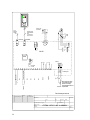
Schéma de raccordement GTM II pour Easyair P
230V/ 50Hz
3
CONTROL
F 16 AT
LNPE
PCB EC
Connecting box
Mains switch and fuses
to be installed by third
parties must comply
to all applicable ruls and
requirements!
Technical changes reserved
1211 12 1334 514 15
0
to input
CONTROL
next PCB
8
AUXILIAR
NL2
PE
230V / 50Hz
Magnetic valve
(OPTIONAL)
L PEN
8
PE
NL2
intern
AUX MON
01.08.2014
la
gezeichnet/signet
Teile
Gruppe
vonPos.
Werkstoff
Maßstab
Blatt
Erstelldatum
GTM II EC UK 140801
Kunde
Benennung
Name
Kundenzeichnung Nr.:
DatumName
1 von 1
6716 17 8 9 10 1918 20
CPU
Adress
switch
0 = MASTER
1 - 9 = SLAVE
5
1
2
3
4
9
8
7
6
ext. Contact
BMS On/Off
Failure
Operation
Frost protection thermostat
free
free
free
optional
optional
Standard supplied
shielded datacable
(20 m)
1:1 straight wired
RJ 45 connentors!
1
M
PE
N
L1
next
Fan
blau/blue
gelb/yellow
weiss/white
rot/red
4
Room Thermostat
optional
ext. Contact
Roomm Thermostat
3
1
4
2
optional
optional
Hand
Stufe
MODE
Y 0-10 V
0 V
+10 V
imp.
Fr 01.08.14 - 11.55

17
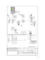
Schéma de raccordement GTM IIE pour Easyair E
CONTROL
PCB EC
Technical changes reserved
1211 12 1334 514 15
0
to input
CONTROL
next PCB
8
AUXILIAR
8
AUX MON
01.08.2014
la
gezeichnet/signet
Teile
Gruppe
vonPos.
Werkstoff
Maßstab
Blatt
Erstelldatum
GTM II E EC UK 140801
Kunde
Benennung
Name
Kundenzeichnung Nr.:
DatumName
1 von 1
6716 17
8 9 10 1918 20
CPU
Adress
switch
0 = MASTER
1 - 9 = SLAVE
5
1
2
3
4
9
8
7
6
ext. Contact
BMS On/Off
Temperature sensor
q
Failure
Operation
free
free
free
optional
Standard supplied
shielded datacabl
(20 m)
1:1 straight wired
RJ-45 connectors
S 50°
K1
K1
K2 K3
S 80°
S 60°
q
q
q
q
K1
free
Connecting box
Mains switch and fuses
to be installed by third
parties must coply
to all applicable rules and
requirements!
1
M
PE
N
L1
next
Fan
blau/blue
gelb/yellow
weiss/white
rot/red
4
step 2
step 3 = step 1 + step 2
step 1
NL2
PE
PE
NL2
intern
230V / 50Hz
L N PE312
F 16 AT
K2K3
4
3~400V/ 50Hz
3
230V/ 50Hz
K0
q
q
ext. Contact
Temperature sensor
3
1
4
2
optional
optional
S 45°
Y 0-10 V
0 V
+10 V
imp.
S 100°
AutoTA 20°C
AKS
15°C
MODE
Fr 01.08.14 - 11.55

18

NL
19
Lees dit document door voordat de
installatie van het toestel begint
Waarschuwing
Een foutief uitgevoerde installatie, afregeling, wijziging, reparatie of onderhoudsbeurt kan
leiden tot materiële schade, verwondingen of explosie. Alle werkzaamheden moeten door
erkende, gekwaliceerde vakmensen worden uitgevoerd. Indien het toestel niet volgens
voorschrift wordt geplaatst, vervalt de garantie.
Indien in de handleiding wordt verwezen naar een afbeelding of tabel, dan wordt een getal tussen
vierkante haken vermeld, bijvoorbeeld [3]. Het nummer verwijst naar afbeeldingen en tabellen
achterin de handleiding met het vermelde nummer.
Algemeen
Alle Mark luchtgordijnen worden gefabriceerd volgens Europeese richtlijnen en de laatste
technische eisen. De kwaliteitscontrole omvat materiaal- en functioneringsproeven tijdens
iedere fase van het productieproces; dit garandeert een eindproduct van hoge kwaliteit en lange
levensduur. Mark luchtgordijnen worden geleverd voor warmwater (60/40°C standaard) of
elektrische verwarming.
Voorwaarden voor een optimale werking van het luchtgordijn
De ruimtetemperatuur is minimaal +4°C en maximaal +40°C.
De uitblaastemperatuur is maximaal +55°C.
Opslag en transport
Open de verpakking bij ontvangst en controleer het luchtgordijn op mogelijke transportschade.
Zichtbare schade dient meteen gemeld te worden. Open de verpakking NIET als beschadigingen
van buitenaf zichtbaar zijn. Sla het luchtgordijn droog op en laat het zo lang mogelijk in de
verpakking om beschadigingen te voorkomen.
Opslagtemperatuur tussen –20 °C en +40 °C.
Zorg ervoor dat het luchtgordijn niet beschadigd wordt tijdens transport.
Opgelet! Zware lading.
Kom niet onder de hangende lading tijdens transport of montage.
Montage
Het luchtgordijn dient zo dicht mogelijk bij de deur gemonteerd te worden. Let erop dat het
revisiedeksel ten allen tijde bereikbaar blijft, ook als het luchtgordijn is uitgevoerd als BP (geschikt
voor montage boven het verlaagd plafond). Montage van het luchtgordijn geschiedt d.m.v. M8
draadeinden (types S, M en L) of M12 draadeinden (type LX), spankoppelingen, trillingsdempers,
glijmoeren en Flamco-proelen aan het plafond. De ophangpunten van het luchtgordijn zijn
standaard voorzien van geïntegreerde M8 (types S, M en G) of M12 (type LX) moeren. Als het
luchtgordijn is uitgevoerd als montage gelijk met het plafond of als montage boven het plafond zijn
er extra ophangpunten in de bovenkant van de aanzuigbak aangebracht. Zie voor de exacte maten
!

ook het betreffende maatblad (op aanvraag beschikbaar). Houd bij het selecteren en toepassen
van montagemateriaal rekening met het gewicht van het luchtgordijn!
Toepassingsvoorbeelden [1] Ophangvoorbeelden [2]
1 Vrijhangende montage 1 Betonplug
2 Montage vóór deurautomaat 2 Trillingsdemper
3 Montage met wandconsoles 3 Spankoppeling
4 Montage gelijk met plafond (GP) 4 Draadeind M8
5 Montage boven plafond (BP) 5 Geïntegreerde moer M8
6 Toepassing in tochtsluis
A Plafondmontage
A Aanzuig B Wandmontage
B Uitblaas
C Buiten
D Binnen
Positie aansluitingen bovenzijde [3]
A Optioneel magneetventiel 230V/50Hz F Naar regelaar
B Besturing G Naar luchtgordijn 2
C Voeding H Naar luchtgordijn 3
D Luchtgordijn 1 I Type I/II (water)
E Eventueel luchtgordijn 2 en volgende J Type IE/IIE (elektrisch)
Waterzijdige aansluitingen
De aanvoer- (IN) en retour (OUT) aansluitingen van de warmtewisselaar bevinden zich
standaard aan de linkerzijde bovenop het luchtgordijn en zijn afhankelijk van het type ½” tot
1½” uitgevoerd (binnendraad). De warmtewisselaar is aan de onderzijde voorzien van een
aftapnippel. De standaard warmtewisselaar is geschikt voor lage temperatuur systemen van
60/40°C. Monteer zowel in de aanvoer- als in de retourleiding afsluiters zo dicht mogelijk bij het
lucht gordijn en een (automatisch) ontluchtingsventiel op het hoogste punt van het leidingwerk.
Opgelet! Alle werkzaamheden moeten voldoen aan locale wet- en regelgeving.
Alle electrische aansluitingen moeten verricht worden door geschoold en
gekwaliceerd personeel.
Uitblaastemperatuurregeling
Met behulp van een optioneel thermostatisch (drieweg-) ventiel wordt de uitblaastemperatuur
constant gehouden. Het ventiel wordt gemonteerd in de aanvoerleiding van het luchtgordijn.
De voeler wordt bevestigd aan de linker ventilator met behulp van de voorgemonteerde
bevestigingsbeugel. Gebruik voor de doorvoer van de voeler de sparing linksboven op het
luchtgordijn (blinddop verwijderen). Zie voor verdere informatie de gebruiksaanwijzing van het
ventiel.
Magneetventiel
De mogelijkheid bestaat om een optioneel magneetventiel 230V/50Hz toe te passen om de
warmwatertoevoer bijvoorbeeld ’s-zomers af te sluiten (alleen water uitvoering). Het ventiel
wordt aangesloten op de klemaansluiting aan de bovenzijde van het luchtgordijn. Deze aansluiting
bevindt zich naast de connector waarop de kabel voor de regelaar wordt aangesloten, zie de
schema’s verderop in deze handleiding.
20
!
Strona się ładuje...
Strona się ładuje...
Strona się ładuje...
Strona się ładuje...
Strona się ładuje...
Strona się ładuje...
Strona się ładuje...
Strona się ładuje...
Strona się ładuje...
Strona się ładuje...
Strona się ładuje...
Strona się ładuje...
Strona się ładuje...
Strona się ładuje...
Strona się ładuje...
Strona się ładuje...
Strona się ładuje...
Strona się ładuje...
Strona się ładuje...
Strona się ładuje...
Strona się ładuje...
Strona się ładuje...
Strona się ładuje...
Strona się ładuje...
Strona się ładuje...
Strona się ładuje...
Strona się ładuje...
Strona się ładuje...
-
 1
1
-
 2
2
-
 3
3
-
 4
4
-
 5
5
-
 6
6
-
 7
7
-
 8
8
-
 9
9
-
 10
10
-
 11
11
-
 12
12
-
 13
13
-
 14
14
-
 15
15
-
 16
16
-
 17
17
-
 18
18
-
 19
19
-
 20
20
-
 21
21
-
 22
22
-
 23
23
-
 24
24
-
 25
25
-
 26
26
-
 27
27
-
 28
28
-
 29
29
-
 30
30
-
 31
31
-
 32
32
-
 33
33
-
 34
34
-
 35
35
-
 36
36
-
 37
37
-
 38
38
-
 39
39
-
 40
40
-
 41
41
-
 42
42
-
 43
43
-
 44
44
-
 45
45
-
 46
46
-
 47
47
-
 48
48


w innych językach
- français: Mark EASYAIR
- English: Mark EASYAIR
- русский: Mark EASYAIR
- Nederlands: Mark EASYAIR
Powiązane artykuły
Inne dokumenty
-
Hendi Arktic Instrukcja obsługi
-
Ferono FK90E3 Instrukcja obsługi
-
Garmin GTM36 Instrukcja obsługi
-
Tristar AT-5450 Instrukcja obsługi
-
-
Reznor AB industrial air curtains Instrukcja obsługi
-
-
 Delta Core DMBD TYXAL + Instrukcja instalacji
-
flamco LS-E 750 Stainless Steel Calorifiers Instrukcja obsługi
-
Haier AS07NS3HRA Operation Manual And Installation Manual
