
P/N: 098-013852-45 Rev.1
Date: 04-22-14
Drawn: TEH
Checked: DMH 04-23-14
Approved: JHB 04-28-14
Part Numbers
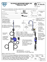
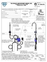
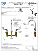
Equip Faucet and Pre-Rinse Unit Parts List
Ceramic Cartridge, Hot 013787-45
Ceramic Cartridge, Cold 013788-45
Handle Screw, Plain (10) 013849-45
Lever Handle Kit (includes color coded screws) 5-HDL-L
3/4-27UN Full Flow Laminar Outlet 014250-45
3” Rigid Gooseneck w/ Laminar Outlet 5SP-03
Nut, Swivel 013839-25
O-Ring, Swivel Piece (10) 013848-45
5-1/2” Swivel Gooseneck w/ Laminar Outlet 5SP-05
6” Swing Nozzle w/ Laminar Outlet 5SP-06
8” Swing Nozzle w/ Laminar Outlet 5SP-08
10” Swing Nozzle w/ Laminar Outlet 5SP-10
12” Swing Nozzle w/ Laminar Outlet 5SP-12
14” Swing Nozzle w/ Laminar Outlet 5SP-14
16” Swing Nozzle w/ Laminar Outlet 5SP-16
18” Swing Nozzle w/ Laminar Outlet 5SP-18
Check Valve, 20mm 013840-45
Check Valve Adapter, 1/2” BSP 010321-45
Overhead Spring, PRU 014068-45
Finger Hook Assembly 004R
Spray Valve Assembly, PRU 5SV
Bonnet Valve Assembly, PRU 002856-40
Bumper, Spray Face & Screw for PRU 5SV-RK
Hose Assembly, 44” 5HSE44
Hose Assembly, 68” 5HSE68
Hose Assembly, 84” 5HSE84
Hose Assembly, 96” 5HSE96
1/2” NPT Supply Nipple Kit (2) B-0425-M
1/2” NPT Male Elbow Kit (2) B-0230-K
1/2” NPT Female Eccentric Flange 00AA
Wall Bracket Assembly, 6” 013716-40
Riser, 18” 000369-40
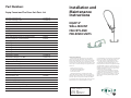
Installation and
Maintenance
Instructions
EQUIP 8”
WALL-MOUNT
FAUCETS AND
PRE-RINSE UNITS
Limited One Year Warranty
Equip warrants to the original purchaser (other than for
purposes of resale) that such product is free from defects in
material and workmanship for a period of one (1) year from the
date of purchase. During this one-year warranty period, if the
product is found to be defective, Equip shall, at its option, repair
and/or replace it. To obtain warranty service, products must be
returned to...
Equip Foodservice Accessories
Attn: Warranty Repair Department
P.O. Box 1088, 2 Saddleback Cove
Travelers Rest, SC 29690
Shipping, freight, insurance, and other transportation
charges of the product to Equip and the return of repaired or
replaced product to the purchaser are the responsibility of the
purchaser. Repair and/or replacement shall be made within a
reasonable time after receipt by Equip of the returned product.
This warranty does not cover Items which have received
secondary nishing or have been altered or modi ed after
purchase, or for defects caused by physical abuse to or
misuse of the product, or shipment of the products.
Any express warranty not provided herein, and any
remedy for Breach of Contract which might arise, is
hereby excluded and disclaimed. Any implied warranties
of merchantability or tness for a particular purpose are
limited to one year in duration. Under no circumstances
shall Equip be liable for loss of use or any special conse-
quential costs, expenses or damages.
Some states do not allow limitations on how long
an implied warranty lasts or the exclusion or limitation
of incidental or consequential damages, so the above
limitations or exclusions may not apply to you. Speci c
rights under this warranty and other rights vary from
state to state.
by

Instructions Instructions
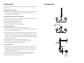
STEP 1
STEP 2
STEP 3
STEP 12
STEP 12
wall or
backsplash
B-0230-K
inlet kit
(available
separately)
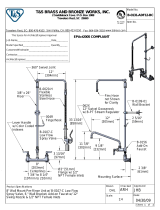
Note: If unit is equipped with a rigid or swivel spout/gooseneck, install spout/
gooseneck rst.
Rigid Gooseneck Installation:
1. Apply Te on tape, Loctite, or pipe joint compound to threads of gooseneck.
Thread gooseneck into outlet hole of body until joint is secure and
gooseneck faces desired direction.
Swing Nozzle/Swivel Gooseneck Installation:
Note: Silicon grease is applied to the interior swivel cavity of the body prior to
shipment. No additional grease is required.
2. Remove plastic cap from body outlet.
3. Insert nozzle/gooseneck into body cavity.
4. Tighten swivel lock nut using 1 5/16” wrench.
Faucet Body Installation:
5. Flush debris from water lines then shut o water supply.
6. Drill two holes, approximately 1” to 1-1/4” diameter, in wall or backsplash of
sink. Holes must be 8” between centers.
7. Install washers and nuts onto B-0230-K supply elbow kits, or similar ½” NPT
inlets, as far onto threaded ends as possible. Apply Te on tape or thread
sealant to ½“ NPT threads of these ends and pass through from back side of
wall openings. Thread elbow ends into the inlet holes of the faucet anges
until the joints are secure.
8. Apply plumbers putty to faucet ange mounting surfaces.
9. Secure faucet in place with supply elbow kit washers and nuts.
10. Connect water supplies to other end of elbows.
Pre-Rinse Installation:
11. After installation of the faucet body per steps 5 through 10, apply Te on
tape, Loctite, or pipe thread compound on the bottom of the riser. Slide
nger hook onto riser before riser installation. Thread riser into outlet hole
of faucet body until joint is secured.
12. Install wall bracket and nger hook, tightening all fasteners securely.
13. Rotate spring and hose assembly until they face desired direction.
14. Turn on water supplies and check for leaks.
-
 1
1
-
 2
2


w innych językach
- English: Equip 5PR-2S00 Installation guide
Inne dokumenty
-
Design House 538587 Instrukcja obsługi
-
 Kingston Brass HCC3162 Instrukcja instalacji
-
 T & S Brass & Bronze Works B-2855-01 Karta katalogowa
-
 T & S Brass & Bronze Works B-0131-ADF12-BC Karta katalogowa
-
LIVARNO 430596 Instrukcja obsługi
-
 T & S Brass & Bronze Works EC-3101-LF22 Karta katalogowa
-
 T & S Brass & Bronze Works EC-3100-LF22 Karta katalogowa
-
Potter RD13 Residential Riser Instrukcja obsługi
-
Sea Ray 2000 270 SUNDANCER Parts Manual
-
 T & S Brass & Bronze Works B-2866-05FC Karta katalogowa


