Novus NVIP-2H-8002M/LPR Instrukcja obsługi
- Kategoria
- Kamery ochrony
- Typ
- Instrukcja obsługi

User’ s ma n u a l
(s h ort form )
NVIP-2H-8002M/LPR

NVIP-2H-8002M/LPR, User’s manual (short) ver.1.0
All rights reserved © AAT Holding S.A.
2
UWAGI I OSTRZEŻENIA IMPORTANT SAFEGUARDS AND WARNINGS
EMC (2014/30/EU) and LVD (2014/35/EU) Directives
CE Marking
Our products are manufactured to comply with requirements of the following directives and national regulations
implementing the directives:
• Electromagnetic compatibility EMC 2014/30/EU.
• Low voltage LVD 2014/35/EU with further amendment. The Directive applies to electrical
equipment designed for use with a voltage rating of between 50VAC and 1000VAC as well as
75VDC and 1500VDC.
WEEE WEEE 2012/19/UE
Information on Disposal for Users of Waste Electrical and Electronic Equipment
This appliance is marked according to the European 1000VAC Directive on Waste Electrical and
Electronic Equipment (2012/19/UE) and further amendments. By ensuring this product is disposed of
correctly, you will help to prevent potential negative consequences for the environment and human
health, which could otherwise be caused by inappropriate waste handling of this product.
The symbol on the product, or the documents accompanying the product, indicates that this appliance may not be
treated as household waste. It shall be handed over to the applicable collection point for used up electrical and
electronic equipment for recycling purpose. For more information about recycling of this product, please contact
your local authorities, your household waste disposal service or the shop where you purchased the product.
RoHS Directive 2011/65/UE
Out of concern for human health protection and friendly environment, we assure that our products
falling under RoHS Directive regulations, regarding the restriction of the use of hazardous
substances in electrical and electronic equipment, have been designed and manufactured in
compliance with the above mentioned regulations. Simultaneously, we claim that our products have
been tested and do not contain hazardous substances whose exceeding limits could have negative
impact on human health or natural environment
Information
The device, as a part of professional CCTV system used for surveillance and control, is not designed for self
installation in households by individuals without technical knowledge.
Excluding of responsibility in case of damaging data on a disk or other devices:
The manufacturer does not bear any responsibility in case of damaging or losing data on a disk or other devices
during device operation.
WARNING!
PRIOR TO UNDERTAKING ANY ACTION THAT IS NOT DESCRIBED FOR THE GIVEN PRODUCT IN
USER’S MANUAL AND OTHER DOCUMENTS DELIVERED WITH THE PRODUCT, OR IF IT DOES
NOT ARISE FROM THE USUAL APPLICATION OF THE PRODUCT, MANUFACTURER MUST BE
CONTACTED UNDER THE RIGOR OF EXCLUDING THE MANUFACTURER’S RESPONSIBILITY FOR
THE RESULTS OF SUCH AN ACTION.

NVIP-2H-8002M/LPR, User’s manual (short) ver.1.0
All rights reserved © AAT Holding S.A.
3
WARUNKI BEZPIECZEŃSTWA
UWAGA!
ZNAJOMOŚĆ NINIEJSZEJ INSTRUKCJI JEST NIEZBĘDNYM WARUNKIEM PRAWIDŁOWEJ
EKSPLOATACJI URZĄDZENIA. PROSIMY O ZAPOZNANIE SIĘ Z NIM PRZED
PRZYSTĄPIENIEM DO INSTALACJI I OBSŁUGI URZĄDZENIA.
UWAGA!
NIE WOLNO DOKONYWAĆ ŻADNYCH SAMODZIELNYCH NAPRAW. WSZYSTKIE
NAPRAWY MOGĄ BYĆ REALIZOWANE JEDYNIE PRZEZ WYKWALIFIKOWANYCH
PRACOWNIKÓW SERWISU.
1. Przed zainstalowaniem i rozpoczęciem eksploatacji należy dokładnie zapoznać się z niniejszą
instrukcją obsługi i zawartymi w niej wymogami bezpieczeństwa;
2. Uprasza się o zachowanie instrukcji na czas eksploatacji kamery na wypadek konieczności
odniesienia się do zawartych w niej treści;
3. Należy skrupulatnie przestrzegać wymogów bezpieczeństwa opisanych w instrukcji, gdyż mają one
bezpośredni wpływ na bezpieczeństwo użytkowników i trwałość oraz niezawodność urządzenia;
4. Wszystkie czynności wykonywane przez instalatorów i użytkowników muszą być realizowane
zgodnie z opisem zawartym w instrukcji;
5. W czasie czynności konserwatorskich urządzenie musi być odłączone od zasilania;
6. Nie wolno stosować żadnych dodatkowych urządzeń lub podzespołów nie przewidzianych
i nie zalecanych przez producenta;
7. Nie należy instalować tego urządzenia w miejscu, gdzie nie można zapewnić właściwej wentylacji
(np. zamknięte szafki, itp.), co powoduje zatrzymanie się ciepła i w konsekwencji może
doprowadzić do uszkodzenia;
8. Nie wolno umieszczać kamery na niestabilnych powierzchniach. Kamera musi być instalowany
przez wykwalifikowany personel o odpowiednich uprawnieniach według zaleceń podanych
w niniejszej instrukcji;
9. Urządzenie może być zasilane jedynie ze źródeł o parametrach zgodnych ze wskazanymi przez
producenta w danych technicznych serwera wideo. Dlatego też, zabrania się zasilania kamery
ze źródeł o nieznanych, niestabilnych lub niezgodnych z wymaganiami określonymi przez
producenta parametrach
UWAGA!
Ponieważ produkt jest stale ulepszany i optymalizowany niektóre parametry i funkcje opisane
w załączonej instrukcji mogły ulec zmianie. Prosimy o zapoznanie się z najnowszą oraz pełna
instrukcją obsługi znajdującą się na stronie www.novuscctv.pl.
Producent, firma AAT Holding S.A. zastrzega sobie możliwość wystąpienia błędów w druku oraz
zmian parametrów technicznych bez uprzedniego powiadomienia.
IMPORTANT SAFEGUARDS AND WARNINGS
WARNING!
THE KNOWLEDGE OF THIS MANUAL IS AN INDISPENSIBLE CONDITION OF A PROPER
DEVICE OPERATION. YOU ARE KINDLY REQEUSTED TO FAMILIARIZE YOURSELF WITH
THE MANUAL PRIOR TO INSTALLATION AND FURTHER DEVICE OPERATION.
WARNING!
USER IS NOT ALLOWED TO DISASSEMBLE THE CASING AS THERE ARE NO USER
-SERVICEABLE PARTS INSIDE THIS UNIT. ONLY AUTHORIZED SERVICE PERSONNEL
MAY OPEN THE UNIT
INSTALLATION AND SERVICING SHOULD ONLY BE DONE BY QUALIFIED SERVICE
PERSONNEL AND SHOULD CONFORM TO ALL LOCAL REGULATIONS
1. Prior to undertaking any action please consult the following manual and read all the safety and operating
instructions before starting the device.
2. Please keep this manual for the lifespan of the device in case referring to the contents of this manual is
necessary;
3. All the safety precautions referred to in this manual should be strictly followed, as they have a direct
influence on user’s safety and durability and reliability of the device;
4. All actions conducted by the servicemen and users must be accomplished in accordance with the user’s
manual;
5. The device should be disconnected from power sources during maintenance procedures;
6. Usage of additional devices and components neither provided nor recommended by the producer is
forbidden;
7. You are not allowed to use the camera in high humidity environment (i.e. close to swimming pools, bath tubs,
damp basements);
8. Mounting the device in places where proper ventilation cannot be provided (e. g. closed lockers etc.) is not
recommended since it may lead to heat build-up and damaging the device itself as a consequence;
9. Mounting the camera on unstable surface or using not recommended mounts is forbidden. Improperly
mounted camera may cause a fatal accident or may be seriously damaged itself. The camera must be mounted
by qualified personnel with proper authorization, in accordance with this user’s manual.
10. Device should be supplied only from a power sources whose parameters are in accordance with those
specified by the producer in the camera technical datasheet. Therefore, it is forbidden to supply the camera
from a power sources with unknown parameters, unstable or not meeting producer’s requirements;
Information
Due to the product being constantly enhanced and optimized, certain parameters and functions described
in the manual in question may change without further notice. We strongly suggest visiting the
www.novuscctv.com website in order to access the newest manual
Data included in the following user’s manual is up to date at the time of printing. AAT Holding S.A. holds
exclusive rights to modify this manual. The producer reserves the rights for device specification
modification and change in the design without prior notice.

NVIP-2H-8002M/LPR, User’s manual (short) ver.1.0
All rights reserved © AAT Holding S.A.
4
TABLE OF CONTENTS..................................................................................................... 4
1. FOREWORD INFORMATION ................................................................................... ..5
1.1. General Characteristics ........................................................................................ 5
1.2. Specification of NVIP-2H-8002M/LPRcamera ............................................... ...6
2. SPECIFICATION .......................................................................................................... ..8
2.1. Camera dimensions .......................................................................................... ...8
2.2. Package contents .............................................................................................. ...8
2.3 Description of connectors and control tools .................................................... ...10
2.4 Cable overview with connectors description ................................................... ...10
3. INSTALLATION ........................................................................................................... 11
3.1 Requirements for LPR camera installation. .................................................... ...11
3.2 Connecting Ethernet cable .............................................................................. ...13
3.3 Camera installation ......................................................................................... ...13
4. START-UP AND INITIAL CAMERA CONFIGURATION .................................... 15
4.1. Starting the IP camera ....................................................................................... 15
4.2. Initial configuration via the web browser ......................................................... 16
4.3. Security recommendations for network architecture and configuration ........... 17
5. NETWORK CONNECTION VIA WEB BROSWER ................................................ 18
5.1. Recommended PC specification for web browser connections ........................ 18
5.2. Connection with IP camera via web browser .................................................... 18
6. WWW INTERFACE - WORKING WITH IP CAMERA ........................................ 21
6.1. Displaying live video. ........................................................................................ 21
6.2. Adding a site to the Compatibility View list ..................................................... 22
6.3. LPR settings configuration ............................................................................... 23
6.3.1. List Configure ................................................................................................. 23
6.3.2. Parameter Configure ...................................................................................... 24
6.3.3. Linkage Configure .......................................................................................... 24
6.3.4. LPR Search .................................................................................................... 25
6.4. Sensor parameters configuration ....................................................................... 25
6.4.1. Schemes and schedules ................................................................................... 25
6.4.2. Sensor menu configuration for LPR camera ................................................. 25
7. ELECTRIC CONNECTORS AND ACCESORIES .................................................. 26
7.1. Connecting power supply to the camera ........................................................... 26
7.2. Connecting alarm inputs/outputs ...................................................................... 26
7.3. SD card installation .......................................................................................... 28
8. RESTORING FACTORY DEFAULTS...................................................................... 29
8.1. Restoring software factory defaults ................................................................... 29
8.2. Restoring hardware factory defaults in IP cameras ........................................... 29
TABLE OF CONTENTS

NVIP-2H-8002M/LPR, User’s manual (short) ver.1.0
All rights reserved © AAT Holding S.A.
5
1. FOREWORD INFORMATION
1.1. General Characteristics
• Imager resolution: 2.0 megapixels
• Mechanical IR cut filter
• IR operation capability
• Min. Illumination from 0.0014 lx/F1.4
• Digital Slow Shutter (DSS)
• Digital Noise Reduction (DNR)
• Defog Function (F-DNR)
• Highlight Compensation (HLC)
• Back Light Compensation (BLC)
• Wide Dynamic Range (WDR)
• Digital Image Stabilization (DIS)
• Lens: motor-zoom, auto-iris and auto-focus function , f=7 ~ 22 mm/F1.4
• Built-in IR illuminator, 8LEDs
• 4 Privacy Mask
• Compression: H.264, H.265, MJPEG
• Max video processing resolution: 1920 x 1080 (Full HD)
• Multi streaming: individually defined compression, resolution, speed and quality
• RTP/RTSP protocol support for video transmission
• Pre & post-alarm functions
• Built-in webserver: camera configuration through the website
• Licence plate recognition (LPR)
• Autonomous operation mode - recognition function implemented in the camera
• Barrier control by built-in relay output
• Recognized number plates of all countries of the European Union, CIS countries, Turkey, Israel,
Switzerland, Norway and others.
• Recognition of plates for vehicles moving from a speed up to 50 km/h.
• Data recorded in the camera base about recognition date/time, number of recognised licence plate,
image of recognised licence plate, system reaction, presence on the "white list" or "black list",
country of origin of the registration plate
• MicroSD card support to 128GB
• Network protocol support : ONVIF (Profile S), HTTP, TCP/IP, IPv4, UDP, HTTPS, FTP, DHCP,
DNS, DDNS, NTP, RTSP, PPPoE, SMTP
• Software: NMS (NOVUS MANAGEMENT SYSTEM) for video recording, live monitoring,
playback and remote IP devices administration
• Built-in Heater
• Degree of Protection IP66
• Power supply: 12VDC and PoE (Power over Ethernet)
FOREWORD INFORMATION

NVIP-2H-8002M/LPR, User’s manual (short) ver.1.0
All rights reserved © AAT Holding S.A.
6
FOREWORD INFORMATION
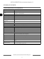
1.2. Specification of NVIP-2H-8002M/LPR camera
Image
Image Sensor 2 MPX CMOS sensor 1/2.8” SONY Exmor R STARVIS
Number of Effective Pixels 1945 (H) x 1097 (V)
Min. Illumination
0.0014 lx/F1.4 - color mode,
0 lx (IR on) - B/W mode
Electronic Shutter auto: 1/5 s ~ 1/20000 s
Digital Slow Shutter (DSS) up to 1/5 s
Wide Dynamic Range (WDR) yes (double scan sensor), 120dB
Digital Image Stabilization (DIS) yes
Digital Noise Reduction (DNR) 2D, 3D
Defog Function (F-DNR) yes
Highlight Compensation (HLC) yes
Back Light Compensation (BLC) yes
Lens
Lens Type motor-zoom, auto-iris function, f=7 ~ 22 mm/F1.4
Auto-focus zoom trigger, manual trigger
Day/Night
Switching Type mechanical IR cut filter
Switching Mode auto, manual, time
Switching Level Adjustment yes
Switching Delay 0 ~ 180 s
Switching Schedule yes
Visible Light Sensor yes
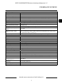
Network
Stream Resolution
1920 x 1080 (Full HD), 1280 x 720 (HD), 704 x 576, 704 x 480,
640 x 480 (VGA), 640 x 360, 352 x 288 (CIF), 320 x 240 (QVGA)
Frame Rate 30 fps for 1920 x 1080 (Full HD) and lower resolutions
Multistreaming Mode 2 streams
Video/Audio Compression H.264, H.265, MJPEG/G.711, RAW_PCM
Number of Simultaneous
Connections
max. 8
Bandwidth 40 Mb/s in total
Network Protocols Support
HTTP, TCP/IP, IPv4, UDP, HTTPS, FTP, DHCP, DNS, DDNS, NTP, RTSP, PPPoE,
SMTP
ONVIF Protocol Support Profile S
Camera Configuration
from Internet Explorer browser
languages: Polish, English, Russian, and others
Compatible Software NMS
Other functions
Privacy Zones 4
Motion Detection yes
Region of interest (ROI) 8
Image Processing 180˚ image rotation, sharpening, mirror effect, corridor mode
Prealarm/Postalarm up to 5 MB/up to 86400 s
System Reaction to Alarm Events e-mail with attachment, saving file on FTP server, saving file on SD card

NVIP-2H-8002M/LPR, User’s manual (short) ver.1.0
All rights reserved © AAT Holding S.A.
7
FOREWORD INFORMATION
License plate recognition (LPR)
Autonomous operation mode yes - recognition function implemented in the camera
Types of recognized number plates
all countries of the European Union / CIS countries / Turkey /
Israel / Switzerland / Norway and others
Barrier control yes - built-in relay output
Recommended maximum
speed of the vehicle
up to 50 km/h
Data recorded in the camera base
recognition date/time, number of recognized license plate, image of recognized li-
cense plate, system reaction, presence on the "white list" or "black list", country of
origin of the registration plate
Reactions for the license plate
recognition
e-mail with attachment, saving file on FTP server, alarm output activation
IR LED
LED Number 8
Range 60 m
Angle 80°
Interfaces
Video Output BNC, 1.0 Vp-p, 75 Ohm - maintenance only
Audio Input/Output 1 x RCA/1 x RCA
Alarm Input/Output 1 (NO/NC)/1 relay type
RS-485 yes
Network Interface 1 x Ethernet - RJ-45 interface, 10/100 Mbit/s
Memory Card Slot SD - capacity up to 128GB
Installation parameters
Dimensions (mm) with bracket: 110 (Ф) x 377 (L)
Weight 1.7 kg
Degree of Protection IP 66 (details in the user’s manual)
Enclosure aluminum, white, fully cable managed wall mount bracket in-set included
Power Supply PoE, 12 VDC
Surge protection TVS 4000 V
Power Consumption
4 W,
14.5 W (IR and heater on)
Operating Temperature -30°C ~ 60°C
Built-in Heater/Fan yes/no

NVIP-2H-8002M/LPR, User’s manual (short) ver.1.0
All rights reserved © AAT Holding S.A.
8
SPECIFICATION
2. SPECIFICATION
2.1. Camera dimensions
Dimensions in mm.
2.2. Package contents
After you open the package make sure that the following elements are inside:
• IP camera,
• Mounting Plate
• Mounting Screw Kit
• RCA-to-BNC Test Cable
• Mounting Template,
• Short version of user’s manual,
If any of this elements has been damaged during transport, pack all the elements back into the original
box and contact your supplier for further assistance.

NVIP-2H-8002M/LPR, User’s manual (short) ver.1.0
All rights reserved © AAT Holding S.A.
9
Caution:
If the device was brought from a location with lower temperature, please wait until it reaches the
temperature of location it is currently in. Turning the device on immediately after bringing it
from a location with lower ambient temperature is forbidden, as the condensing water vapour
may cause short-circuits and damage the device as a result.
Before starting the device familiarize yourself with the description and the role of particular
inputs, outputs and adjusting elements that the device is equipped with.
Caution:
In order to provide protection against voltage surges/lightning strikes, usage of appropriate surge
protectors is advised. Any damages resulting from surges are not eligible for service repairs.
Caution:
It is forbidden to use – as the camera power source – PoE equipment (adapters, etc.) not compatible
with IEEE 802.3af standard (items called “passive PoE power supply”). Damages that results from
the usage of improper power supply source are not covered by the warranty.
Caution:
Camera connectors / sockets are not hermetic. The user should ensure their hermeticity on his
own.
Caution:
Please note that the wall or ceiling must have enough strength to support the IP Camera.
Caution:
In order to obtain declared degree of protection please seal the camera base to prevent water
getting inside. Furthermore, when installing the camera on rough/uneven surfaces, please
additionally seal the junction with appropriate sealing mass. Please pay special attention to any
mounting holes and if they are a loop-through ones, seal them too.
Caution:
The declared degree of protection of the camera relates to its housing and does not take into account
the possibility of moisture infiltration into the interior of the camera by connecting cables.
Connection cables protection through i.e. sealing up is the responsibility of the camera installer. The
manufacturer is not liable for any damages to the camera caused as a result of failing in performing
that activity by installer, which also means that camera damaged in that way is not subject to
warranty repairs.
SPECIFICATION

NVIP-2H-8002M/LPR, User’s manual (short) ver.1.0
All rights reserved © AAT Holding S.A.
10
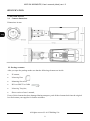
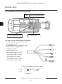
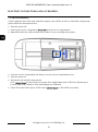
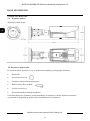
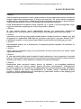
2.3. Description of connectors and control tools
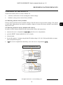
2.4. Cable overview with connectors description
1. 100 Mb/s Ethernet port (RJ-45 connector)
2. Power supply 12VDC
CAUTION! Please pay attention to ensure
the correct power supply polarity!
3. Audio Input (RCA)
4. Audio Output (RCA)
5. Alarm input/output connectors
- alarm input (COM0 - orange)
- alarm input (IN0 - yellow)
- alarm output (COM1 - purple)
- alarm output (OUT1 - grey)
SPECIFICATION
Status
LEDs
Reset button
(reverts to factory defaults)
SD card slot
(max. 64GB supported)
RCA service
analog output
12 VDC +
12 VDC -
12 VDC power supply connection diagram

NVIP-2H-8002M/LPR, User’s manual (short) ver.1.0
All rights reserved © AAT Holding S.A.
11
3. INSTALLATION
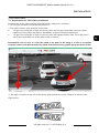
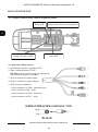
3.1. Requirements for LPR camera installation.
Requirements for the camera and the image subjected to analysis are as follows :
1. Licence plate should be well lit and not obstructed
2. The width of licence plate should be no less than:
• 150 pixel for rectangular of single row licence plates and 100 pixel for double row licence plates
(applies to license plates from Russia, Kazakhstan, Armenia, Uzbekistan and Serbia)
• 130 pixel for rectangular of single row licence plates (the optimal width is from 150 to 200 pixels)
and 70 pixel for double row licence plates (other countries)
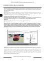
Information: One of ways to verify the width of the plate in the image is to take a screenshot
from the camera, and then measure the width of the board in any graphic program such as Paint.
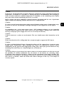
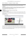
3. The angle of rotation in the axis of the license plate should not exceed 5 degrees as shown in the
figure below:
INSTALLATION
1
2
1

NVIP-2H-8002M/LPR, User’s manual (short) ver.1.0
All rights reserved © AAT Holding S.A.
12
4. The recommended camera settings for license plate recognition are the default settings of the
NVIP-2H-8002M/LPRcamera, however, you may need to change these settings depending on the
conditions prevailing at the camera installation site and the scene observed by the camera.
The details about basic configuration parameters are described in chapter 6.4 of this manual.
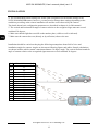
5. The vertical and horizontal tilt angle of camera relative to the recognized signs must not exceed
combined 30 degrees.
6. Make sure that the light does not fall on the number plate (visible as well as infrared).
7. Make sure the camera does not (directly or by reflection) observe the sun.
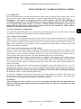
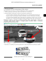
Installation should be carried out keeping the following assumptions about field of view and
installation angles for camera. Angles are shown on following figures and tables. Sample calculations
are shown in tables which contain a maximum distance 30 degree angle. The vertical and horizontal tilt
angle of camera relative to the recognized signs must not exceed combined 30 degrees.
INSTALLATION
h [m] Minimal distance x [m]
1 1,7
1,5 2,6
2 3,4
2,5 4,3
3 5,1
3,5 6
4 6,8
Y [m] Minimal distance x [m]
1 1,7
1,5 2,6
2 3,4
2,5 4,3
3 5,1
3,5 6
4 6,8

NVIP-2H-8002M/LPR, User’s manual (short) ver.1.0
All rights reserved © AAT Holding S.A.
13
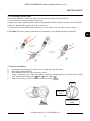
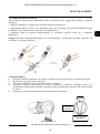
3.2 Connecting Ethernet cable
To maintain tightness of Ethernet cable connection, please follow instruction below:
1. Loosen the nut (a) from the main element (b).
2. Run power cable (without RJ-45 connector) though both elements. Then crimp the cable with RJ-45
connector. Install rubber gasket (d) on the connector (c).
3. Connect the cable to the hermetic connector (c), screw main cover (b), then screw the nut (a).
CAUTION! The other camera connectors are not hermetic. User should seal them by himself.
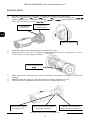
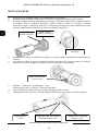
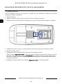
3.3 Camera installation
Put mounting drawing paper to the wall or ceiling and mark drill holes.
Drill holes using markings.
Drill additional hole for video and power cables.
Using mounting screws from the package, attach the mounting plate of camera to the ceiling/
wall. Align the mounting plate the mark facing .
Make sure the hinge screw is attached to the back of the
INSTALLATION
a
b
a
b
c
d
TOP
Mounting screw
holes
Mounting
plate
Hinge screw

NVIP-2H-8002M/LPR, User’s manual (short) ver.1.0
All rights reserved © AAT Holding S.A.
14
Put video and power cables through a previously drilled hole in the wall/ceiling.
Align the mark on camera with the mark on the mounting plate,
camera approximately 10° clockwise, and then the counterclockwise to slide the
hinge screw into the notch on the plate.
Attach the camera to the mounting plate using the allen screws.
(Optional) Unscrew the service compartment open the service compartment. Connect
the RCA service analog output to monitor.
Make connections of all necessary electrical connectors (description in chapter 7 of this user’s
manual).
Manually point the camera in a desired direction to obtain a desired scene view.
Close the service compartment and screw the service compartment screw.
INSTALLATION
TOP mark on
camera base
TOP mark on
mounting plate
Mounting plate notch
Service compartment
Allows you to rotate
the camera 360°
Allows you to tilt the camera
and camera stand 90°
Allows you to rotate the
camera and camera stand 360°

NVIP-2H-8002M/LPR, User’s manual (short) ver.1.0
All rights reserved © AAT Holding S.A.
15
4. START-UP AND INITIAL CAMERA CONFIGURATION
4.1. Starting the IP camera
To run NOVUS IP camera you have to connect ethernet cable between camera and network switch
with PoE support (IEEE 802.3af).
You can also connect it directly via power supply adapter with parameters compatible with camera
power supply specification. The description of connecting power supply to the camera is in chapter 7.
After connecting power status red LED should light on. Initialization process is then started which can
take about 2 minutes. You can then proceed to connect to the camera via web browser.
If the connection is successfully established green network status LED blinks with a frequency
proportional to the quantity of data sent
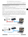
The recommended way to start an IP camera and perform its configuration is a connection directly
to the network switch which is not connected to other devices. To obtain further information about
network configuration parameters (IP address, gateway, network mask, etc.) please contact your
network administrator.
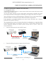
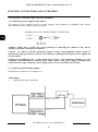
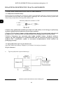
• Connection utilising network switch with PoE support
• Connection utilising external power supply and network switch
START-UP AND INITIAL CAMERA CONFIGURATION
Computer
Power supply and
network transmission
Network
transmission
Network Switch
PoE
IP Camera
Network
transmission
Network Switch
Computer
Network
transmission
IP Camera
PSU

NVIP-2H-8002M/LPR, User’s manual (short) ver.1.0
All rights reserved © AAT Holding S.A.
16
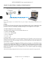
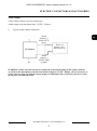
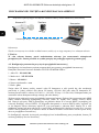
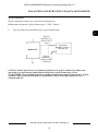
• Connection utilising external power supply directly to the computer
Information:
Power supply adapter is not included. Please use power adapter with parameters specified in user’s
manual.
Caution:
In order to provide protection against voltage surges/lightning strikes, usage of appropriate surge
protectors is advised. Any damages resulting from surges are not eligible for service repairs.
4.2. Initial configuration via the web browser
The default network settings for NVIP-2H-8002M/LPRcamera are :
1. IP address= 192.168.1.200
2. Network mask - 255.255.255.0
3. Gateway - 192.168.1.1
4. User name - root
5. Password - pass
Knowing the camera’s IP address you need to appropriately set PC IP address, so the two devices can
operate in one network subnet ( e.g. for IP 192.168.1.1, appropriate address for the camera ranges from
192.168.1.2 to 192.168.1.254, for example 192.168.1.60). It is not allowed to set the same addresses for
camera and PC computer
You can either set a network configuration (IP address, gateway, net mask, etc.) of NOVUS IP camera
yourself or select DHCP mode (DHCP server is required in this method in target network) by using
web browser or by NMS software. When you use DHCP server check IP address lease and its linking
with camera MAC address to avoid changing or losing IP address during device operation or network/
DHCP server breakdown. You have to remember to use a new camera IP address after changing
network parameters.
After network setting configuration has been done, the camera can be connected to a target network.
START-UP AND INITIAL CAMERA CONFIGURATION
Network transmission - cross over cable
Computer
PSU
IP Camera

NVIP-2H-8002M/LPR, User’s manual (short) ver.1.0
All rights reserved © AAT Holding S.A.
17
4.3. Security recommendations for network architecture and configuration
WARNING!
Below are shown security recommendations for network architecture and configuration
of CCTV systems that are connected to the Internet to reduce the risk
of unauthorized interference with the system by a third party.
1. Absolutely change the default passwords and user names (if the device gives this possibility) of
all applied network devices (recorders, cameras, routers, network switches, etc.) to the
severely complexity password. Use lowercase and uppercase letters, numbers, and special characters
if there is such possibility.
2. Depending on the available functionality in the order to restrict access to the used network devices at
the administrator account level, it is recommended to configure the users accounts accordingly.
3. Do not use DMZ function (Demilitarized zone) in your router. Using that function you open the
access to recorder system from the Internet on all ports, which gives possibility for an unauthorized
interference with the system.
Instead of DMZ use port forwarding redirect only the ports which are necessary for the performance
of the connection (detailed information about ports of communication in different models of recorders,
cameras, etc. can be found in the operating instructions).
4. Use routers with firewall function and make sure it is enabled and properly configured.
5. It is recommended to change the default network communication port numbers of used devices
if there is such possibility.
6. If used network devices has a UPnP feature and it is not used, turn it off.
7. If used network devices has a P2P feature and it is not used, turn it off.
8. If used network devices support HTTPS protocol for connection, it is recommended to use it.
9. If used network devices support IP filtering for authorized connections function, it is recommended
to use it.
10. If used recorder has two network interfaces it is recommended to use both of them to physically
separate network for cameras and network for Internet connection. The only device in the system,
accessible from Internet will be recorder - there will be no physically access directly to any camera.
START-UP AND INITIAL CAMERA CONFIGURATION

NVIP-2H-8002M/LPR, User’s manual (short) ver.1.0
All rights reserved © AAT Holding S.A.
18
5. NETWORK CONNECTION VIA WEB BROSWER
5.1. Recommended PC specification for web browser connections
Requirements below apply to connection with an IP camera, assuming image display in 1920 x 1080
resolution and 25 fps speed.
1. Procesor Intel Core i5 3 GHz lub wyższy
2. Pamięć RAM min. 4 GB
3. Karta grafiki NVidia GeForce z 512 MB
4. System operacyjny Windows 7 / 8 / 8.1 / 10
5. Karta sieciowa 100/1000 Mb/s
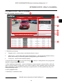
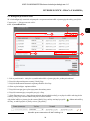
5.2. Connection with IP camera via web browser
Caution:
To maintain correct operation as snapshot or video recording you must enable the browser as an
administrator, also to maintain correct operation as playback from the microSD card you must
add IP camera address to Compatibility View in browser settings.
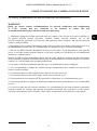
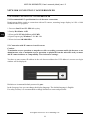
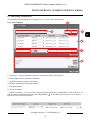
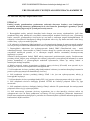
You have to enter camera IP address in the web browser address bar. If IP address is correct user login
window will be displayed:
Default user is root and default password is pass.
In the Language box you can change the display language. The default language is English.
For safety reasons, it is recommended to change default user name and password.
NETWORK CONNECTION VIA WEB BROSWER

NVIP-2H-8002M/LPR, User’s manual (short) ver.1.0
All rights reserved © AAT Holding S.A.
19
NETWORK CONNECTION VIA WEB BROSWER
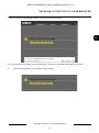
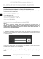
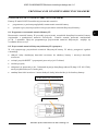
If you’re first time running the camera, you will see screen as below.
To correctly camera working, you need a plugin, you have to download and install it as below.
• Click Download and setup and follow the prompts.
Download and setup
Download and setup

NVIP-2H-8002M/LPR, User’s manual (short) ver.1.0
All rights reserved © AAT Holding S.A.
20
NETWORK CONNECTION VIA WEB BROSWER
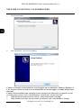
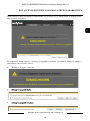
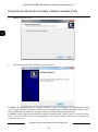
• Click Install button
• After installation, click Finished button
Caution: In Windows Vista/7/8/10 the ActiveX applet may be blocked by Windows Defender or
User account control. In such case you should allow to run this applet, or simply disable these
functions.
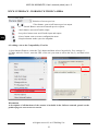
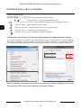
Caution: If the installation fails, changing security settings for the IE browser is required. In order
to do that, please choose: Tools > Internet options > Security tab > Custom level and:
• Under Download unsigned ActiveX controls - select either Enable or Prompt
• Under Initialize and script ActiveX controls not marked as safe - select Enable or Prompt
Strona jest ładowana ...
Strona jest ładowana ...
Strona jest ładowana ...
Strona jest ładowana ...
Strona jest ładowana ...
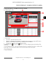
Strona jest ładowana ...
Strona jest ładowana ...
Strona jest ładowana ...
Strona jest ładowana ...
Strona jest ładowana ...
Strona jest ładowana ...
Strona jest ładowana ...
Strona jest ładowana ...
Strona jest ładowana ...
Strona jest ładowana ...
Strona jest ładowana ...
Strona jest ładowana ...
Strona jest ładowana ...
Strona jest ładowana ...
Strona jest ładowana ...
Strona jest ładowana ...
Strona jest ładowana ...
Strona jest ładowana ...
Strona jest ładowana ...
Strona jest ładowana ...
Strona jest ładowana ...
Strona jest ładowana ...
Strona jest ładowana ...
Strona jest ładowana ...
Strona jest ładowana ...
Strona jest ładowana ...
Strona jest ładowana ...
Strona jest ładowana ...
Strona jest ładowana ...
Strona jest ładowana ...
Strona jest ładowana ...
Strona jest ładowana ...
Strona jest ładowana ...
Strona jest ładowana ...
Strona jest ładowana ...
-
 1
1
-
 2
2
-
 3
3
-
 4
4
-
 5
5
-
 6
6
-
 7
7
-
 8
8
-
 9
9
-
 10
10
-
 11
11
-
 12
12
-
 13
13
-
 14
14
-
 15
15
-
 16
16
-
 17
17
-
 18
18
-
 19
19
-
 20
20
-
 21
21
-
 22
22
-
 23
23
-
 24
24
-
 25
25
-
 26
26
-
 27
27
-
 28
28
-
 29
29
-
 30
30
-
 31
31
-
 32
32
-
 33
33
-
 34
34
-
 35
35
-
 36
36
-
 37
37
-
 38
38
-
 39
39
-
 40
40
-
 41
41
-
 42
42
-
 43
43
-
 44
44
-
 45
45
-
 46
46
-
 47
47
-
 48
48
-
 49
49
-
 50
50
-
 51
51
-
 52
52
-
 53
53
-
 54
54
-
 55
55
-
 56
56
-
 57
57
-
 58
58
-
 59
59
-
 60
60


Novus NVIP-2H-8002M/LPR Instrukcja obsługi
- Kategoria
- Kamery ochrony
- Typ
- Instrukcja obsługi
w innych językach
- English: Novus NVIP-2H-8002M/LPR User manual
Powiązane dokumenty
-
Novus NVIP-2H-8002M/LPR Instrukcja obsługi
-
-
-
-
-
-
-
-
-
