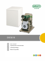
EKOM DK50 B Instrukcja obsługi
- Kategoria
- Sprężarki powietrza
- Typ
- Instrukcja obsługi

DK50 B
User manual
Руководство пользователя
Instrukcja obsługi
Návod na použitie


COMPRESSOR
КОМПРЕССОР
SPRĘŻARKA
KOMPRESOR
DK50 B
EKOM spol. s r. o.
Priemyselná 5031/18
SK-921 01 Piešťany
Slovak Republic
tel.: +421 33 7967255
fax: +421 33 7967223
www.ekom.sk
email: ekom@ekom.sk
DATE OF LAST REVISION
ДАТА ПОСЛЕДНЕЙ РЕДАКЦИИ
DATA OSTATNIEJ AKTUALIZACJI
DÁTUM POSLEDNEJ REVÍZIE
06/2023
NP-DK50 B-A-2_06-2023
112000504-000

CONTENTS .................................................................................................. 4
ОГЛАВЛЕНИЕ ............................................................................................. 28
SPIS TREŚCI ............................................................................................... 51
OBSAH ........................................................................................................ 75

CONTENTS
06/2023 5 NP-DK50 B-A-2_06-2023
CONTENTS
GENERAL INFORMATION ............................................................................................................ 6
1. CONFORMITY WITH THE REQUIREMENTS OF THE EUROPEAN UNION ................... 6
2. SYMBOLS ........................................................................................................................ 6
3. DEVICE USE ................................................................................................................... 7
4. GENERAL SAFETY INSTRUCTIONS .............................................................................. 7
5. STORAGE AND TRANSPORT CINDITIONS ................................................................... 9
PRODUCT DESCRIPTION .......................................................................................................... 10
6. VARIANTS ..................................................................................................................... 10
7. PRODUCT FUNCTION .................................................................................................. 10
TECHNICAL DATA ...................................................................................................................... 12
INSTALLATION ........................................................................................................................... 13
8. INSTALLATION CONDITIONS ...................................................................................... 13
9. INSTALATION CONDITIONS ........................................................................................ 14
10. PNEUMATIC CONNECTION ......................................................................................... 15
11. ELECTRICAL CONNECTION ........................................................................................ 15
12. COMMISSIONING ......................................................................................................... 16
13. ELECTRICAL DIAGRAMS ............................................................................................. 16
OPERATION ................................................................................................................................ 17
14. SWITCHING ON THE COMPRESSOR .......................................................................... 18
15. SWITCHING OFF THE COMPRESSOR ........................................................................ 18
PRODUCT MAINTENANCE ........................................................................................................ 19
16. PRODUCT MAINTENANCE ........................................................................................... 19
17. LONG-TERM SHUTDOWN ............................................................................................ 25
18. DISPOSAL OF DEVICE ................................................................................................. 25
TROUBLESHOOTING ................................................................................................................. 26
19. REPAIR SERVICE ......................................................................................................... 27
ANNEX ........................................................................................................................................ 98
20. INSTALLATION RECORD ............................................................................................. 98

GENERAL INFORMATION
NP-DK50 B-A-2_06-2023 6 06/2023
GENERAL INFORMATION
Carefully read this user manual before using the product and carefully store it for future reference.
The user manual aids in the proper use, including installation, operation and maintenance, of the
product.
The user manual corresponds to the configuration of the product and its compliance with applicable
safety and technical standards at the time of its printing. The manufacturer reserves all rights for the
protection of its configuration, processes and names.
The Slovak version represents the original version of the user manual. The translation of the user
manual is performed in accordance with the best available knowledge. The Slovak version is to be
used in the event of any uncertainties.
The user manual is original and the translation is performed with the best available knowledge.
1. CONFORMITY WITH THE REQUIREMENTS OF THE EUROPEAN UNION
This product conforms to the requirements of the European Union 2006/42/EC, 2014/29/EU,
2014/35/EU, 2014/30/EU, 2011/65/EU and is safe if used in compliance with the intended use and
if all safety instructions are followed.
User manual is in compliance with requirements of Directive 2006/42/EC.
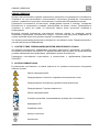
2. SYMBOLS
The following symbols and marks are used in the User manual, on the device and its packaging:
General warning
Warning - risk of electric shock
Warning - compressor is controlled automatically
Warning - hot surface
General caution
Refer to instruction manual
CE – marking
Serial number
Article number
Protecting earthing
Terminal for ground connection

GENERAL INFORMATION
06/2023 7 NP-DK50 B-A-2_06-2023
Package handling label – fragile
Package handling label – this side up
Package handling label – keep dry
Package handling label – temperature limits
Package handling label – limited stacking
Package label – recyclable material
Manufacturer
3. DEVICE USE
3.1. Intended use
The compressor is used as source of clean oil-free compressed air intended to be used in industry
and laboratories, where parameters and properties of the compressed air are suitable.
The compressor is exclusively intended to compress air without content of explosive or chemically
unstable substances.
The compressor is intended for operation in clean and dry rooms.
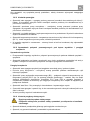
3.2. Incorrect use
Contamination risk.
Air from the compressor is without additional treatment not suitable for breathing
and direct contact with food
Explosion risk.
The product is not intended for operation in rooms with explosion risk.
The compressor must not be used to compress aggressive gases.
The compressor must not be operated in premises with occurrence of flammable vapors.
The compressor must not be operated in other conditions as mentioned in Technical data.
Any other use of the product beyond the intended use is considered as incorrect use. The
manufacturer is not responsible for any damages or injuries as a result of incorrect use or
disobedience to instructions stated in this User manual. All risks shall be solely borne by the
user/operator.
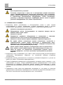
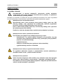
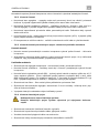
4. GENERAL SAFETY INSTRUCTIONS
The product is designed and manufactured so that any risks connected with its use are minimized
and the product is safe for the user and surrounding when used according to the intended use and
the instructions stated below are followed.

GENERAL INFORMATION
NP-DK50 B-A-2_06-2023 8 06/2023
4.1. Required qualification of the personnel
• Each user must be trained by the manufacturer or an organization authorized by the
manufacturer or instructed on the device operation by other trained user.
• Installation, new settings, changes, extensions and repairs of the product may be performed by
the manufacturer or an organization authorized by the manufacturer (hereinafter qualified
technician).
- Otherwise the manufacturer is not responsible for safety, reliability and correct functioning
of the product.
4.2. General instructions
• When operating the compressor, all acts and local regulations valid in the place of use must be
observed. The operator and user are responsible for following the applicable regulations.
• Before every use, the user must check, if the device is functioning correctly and safely. Before
building the compressor in other devices, the supplier must assess, if the supplied air and
construction of the device comply with the requirements of the specified intended use. Taking
this into account, follow the product technical data. Assessment of conformity shall be performed
by the manufacturer – supplier of the final product.
4.3. Protection from dangerous voltage and pressure
• The equipment may only be connected to a properly installed socket connected to earth
(grounded).
• Before the product is plugged in, make sure that the mains voltage and frequency stated on the
product are the same as the power mains.
• Check for any damage to the connected compressed air system and electrical circuits before
use. Replace damaged pneumatic and electrical conductors immediately.
• Immediately disconnect the product from the mains (remove the power cord from the socket) in
hazardous situations or when a technical malfunction occurs.
• Never adjust or use the safety valve to release the air pressure in the air tank.
• Never adjust or use pressure relief valves to release air pressure from the device.
4.4. Original spare parts and accessories
• Only the use of original parts guarantees the safety of operating personnel and flawless operation
of the product itself. Only accessories and replacement parts specified in the technical
documentation or expressly approved by the manufacturer may be used.
• The warranty does not cover damage resulting from the use of other accessories and
replacement parts as specified or recommended by the manufacturer and the manufacturer has
no related liability.

GENERAL INFORMATION
06/2023 9 NP-DK50 B-A-2_06-2023
5. STORAGE AND TRANSPORT CINDITIONS
The compressor is shipped from the manufacturer in transport packaging. This protects the product
from damage during transport.
Potential for damage to pneumatic components.
The compressor must be transported only when all air has been vented. Before
moving or transporting the compressor, release all the air pressure from the tank
and pressure hoses, from dryer chambers and drain condensate from the tank
and from the condensate separator on the dryer.
Keep the original factory packaging in case the device needs to be returned Use
the original factory packaging during transport as it provides optimum protection
for the product. If it is necessary to return the product during the warranty period,
the manufacturer is not liable for damages caused by improper packaging.
The compressor is shipped in a vertical position and must be secured using
transport straps.
Protect the compressor from humid and dirty environments and extreme temperatures
during transport and storage. Do not store near any volatile chemical substances.
If not, please dispose of the original packaging material in an environmentally-friendly
way. The packaging cardboard can be recycled with old paper.
5.1. Ambient conditions
Products may only be stored and transported in vehicles that are free of any traces of volatile
chemicals under the following climactic conditions:
Temperature
–25°C to +55°C, 24 h at up to +70°C
Relative humidity
max. 90% (non-condensing)
Storing or shipping the equipment in any conditions other than those specified below is
prohibited.

PRODUCT DESCRIPTION
NP-DK50 B-A-2_06-2023 10 06/2023
PRODUCT DESCRIPTION
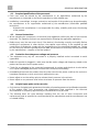
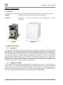
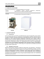
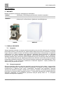
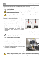
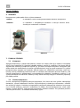
6. VARIANTS
The compressor is manufactured according to its intended application in the following variants:
DK50 B
compressor on base for stand-alone room installations
DK50 BS
compressor in cabinet with effective noise dampening for room
installations
DK50 B
DK50 BS
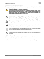
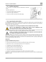
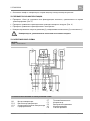
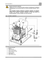
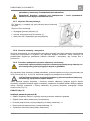
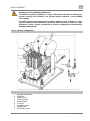
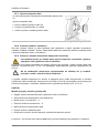
7. PRODUCT FUNCTION
7.1. Compressor
The compressor (1) draws in air through a filter (8) and compresses it through a check valve (3) into
an air tank (2). The connected apparatus draws the compressed air from the air tank until the
pressure drops to a default preset level on the air-pressure switch (4) switching the compressor on.
The compressor again compresses air into the nozzle until the maximum pressure is reached and
the compressor switches off. After compressor aggregate is switched off, pressure hose shall be
pressure-release solenoid valve (13). Safety valve (5) prevents the pressure in air chamber from
rising above the maximal allowed value. The time of work of a compressor is recorded on an
operation clock. The drain valve (7) releases the condensate from the air nozzle. Compressed, clean
air free from oil traces is stored in the air tank ready for use.
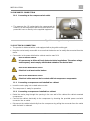
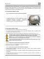
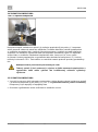
7.2. Compressor cabinet
The soundproof box is compact yet allows sufficient exchange of cooling air. It can be placed in a
dentist’s office. The ventilator under the aggregate of a compressor provides cooling of compressor
and it is in operation at the same time with an engine of the compressor. After prolonged use the
temperature in the case may rise above 40°C, causing the cooling fan blower to automatically turn
on. After cooling the case area to 32°C the fan blower turns off automatically.

PRODUCT DESCRIPTION
06/2023 11 NP-DK50 B-A-2_06-2023
Risk of compressor overheating.
Make sure that there are no obstacles at the cooling air inlet into the cabinet
(around the bottom part of the cabinet) and at the hot air outlet on the top back
side of the cabinet.
If the compressor is placed on a soft floor, e.g. carpet, create space between the
base and the floor or the cabinet and the floor, e.g. underlay the footings with
hard pads to ensure sufficient cooling of the compressor.
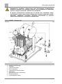
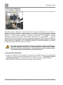
Fig. 1: DK50 B - Compressor
Description to figure:
1 Air pump
2 Air tank
3 Non-return valve
4 Pressure switch
5 Safety valve
6 Pressure gauge
7 Outlet valve
8 Inlet filter
9 Solenoid valve

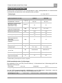
TECHNICAL DATA
NP-DK50 B-A-2_06-2023 12 06/2023
TECHNICAL DATA
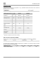
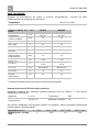
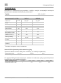
Compressors are designed for operation in dry, ventilated and dust-free indoor rooms under the
following climactic conditions:
Temperature
+5°C to +40°C
Relative humidity
max. 70%
Working pressure 9.5 – 11.5 bar
DK50 B
DK50 BS
Rated voltage
Frequency
V, Hz
230, 50
230, 60 a)
230, 50
230, 60 a)
Capacity at 10 bar
l/min
50
50
Working pressure
bar
9.5 – 11.5
9.5 – 11.5
Rated current
A
3.5
3.5
Motor power
kW
0.55
0.55
Air tank volume
l
4
4
Maximum operating
pressure of safety
valve
bar
12
12
Noise level at 5 bar
(LpA)
dB
≤65
≤45
Operating mode
%
Intermittent
S 3-50
Intermittent
S 3-50
Dimensions (net)
w x d x h
mm
290x430x490
380x525x575
Net weight
kg
35
47
Net weight in
packaging
kg
37
49
a) Specify the compressor version when ordering
FAD correction of capacity for altitude
Capacity given in the form of FAD („Free Air Delivery“) applies to the following conditions:
Altitude
0 m.n.m.
Temperature
20°C
Atmospheric pressure
101325 Pa
Relative humidity
0%
To calculate FAD compressor capacity in dependence on altitude, it is necessary to apply correction
factor according to the following table:
Altitude [m.n.m.]
0 -1500
1501 - 2500
2501 - 3500
3501 - 4500
FAD correction factor
1
0.80
0.71
0.60

INSTALLATION
06/2023 13 NP-DK50 B-A-2_06-2023
INSTALLATION
Risk of incorrect installation.
Only a qualified technician may install the compressor and place it into operation
for the first time. Their duty is to train operating personnel on the use and
maintenance of the equipment. An entry is made in the equipment installation
record to certify installation and operator training.
8. INSTALLATION CONDITIONS
• The compressor may only be installed and operating in dry, well-ventilated and clean
environments under the conditions specified in the Technical Data chapter.
Risk of damage to the device.
The equipment may not be operated outdoors or in otherwise wet or damp
environments.
Risk of explosion.
Do not use the equipment in the presence of explosive gases, dust or
combustible liquids.
Burn or fire hazard! Caution! Hot surface!
Portions of the compressor may be hot and reach hazardous temperatures
during compressor operation that may harm materials or operating staff.
You may notice a “new product” odour when you first place the product into
service (for a short period of time). This odour is temporary and does not impede
the normal use of the product. Ensure the space is properly ventilated after
installation.
• The compressor must be installed so that it is accessible at all times for operating and
maintenance. Please ensure that the nameplate on the device is readily accessible.
• The compressor must stand on a flat, sufficiently stable base (be aware of the weight of the
compressor, see the Technical Data chapter).
• Before connecting the compressor to equipment, the supplier must confirm that it meets all
requirements for its use. Refer to the technical data of the product for this purpose. When a unit
is to be built-in, classification and evaluation of compatibility must be done by the manufacturer
or supplier of the product to be used.
• Any use other than that described in this manual is not covered by the guarantee, and the
manufacturer is not liable for any damages that may result. The operator/user assumes all risk.

INSTALLATION
NP-DK50 B-A-2_06-2023 14 06/2023
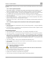
9. INSTALATION CONDITIONS
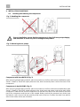
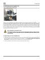
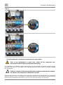
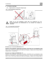
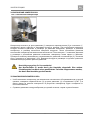
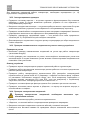
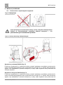
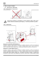
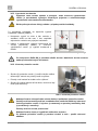
9.1. Handling and releasing the compressor
Fig. 2: Handling the compressor
Prior to installation, ensure that the compressor is free of all transport packaging
and stabilizers to avoid any risk of damage to the product
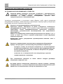
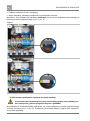
Fig. 3: Releasing the air pumps
Compressor with base DK50 B (Fig. 3)
After removing all packaging material, place the product on the floor and remove stabilization parts
X and Y (Detail A). Direct the output pressure hose, drain hose and power cord out the back of the
compressor.
Compressor in box DK50 BS (Fig. 3)
After removing all packaging material, place the product on the floor and remove stabilization parts
X and Y (Detail A). Direct the output pressure hose, drain hose and power cord out the back of the
compressor. Slide the box over the compressor so that the front face of the box matches the front
part of the compressor and the box is fully seated. Make sure that the pressure hose, drain hose
and electric cord come out via the opening at the back of the box. Position the drain hose with its
valve in the holder at the rear of the box.

INSTALLATION
06/2023 15 NP-DK50 B-A-2_06-2023
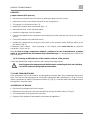
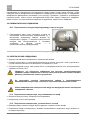
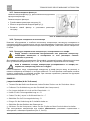
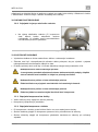
10. PNEUMATIC CONNECTION
10.1. Connecting to the compressed air outlet
• The pressure line (2) is attached to the compressed air
outlet (1) on the compressor and connect the hose to the
pneumatic hose or directly to the supplied equipment.
Fig. 4: Connecting to the compressed air outlet
11. ELECTRICAL CONNECTION
• The product is delivered with a cord equipped with a plug with earthing pin.
• Keep the socket easily accessible to ensure that the device can be safely disconnected from the
mains.
• Connection to the power distribution cabinet must be max.16 A
Risk of electric shock.
It is necessary to follow all local electro technical regulations. The mains voltage
and frequency must comply with the data stated on the device label.
Risk of fire and electric shock.
Electrical cord must not be broken.
Risk of fire and electric shock.
Electrical cable must not be in contact with hot compressor components.
11.1. Connecting a compressor not installed in a cabinet
• Insert the mains plug into a rated mains socket.
• The compressor is ready for operation.
11.2. Connecting a compressor installed in a cabinet
• Route the mains plug through the opening in the rear wall of the cabinet for cabinet-mounted
compressors.
• Connect the cabinet electrically to the compressor by inserting the provided power cord with
connector into an outlet.
• Disconnect the cabinet electrically from the compressor by pulling the connector from the outlet
while the latch is released.
2
1

INSTALLATION
NP-DK50 B-A-2_06-2023 16 06/2023
12. COMMISSIONING
• Make sure all transport stabilizers were removed. (Fig. 3)
• Check that all compressed air hose connections are correct. (Fig. 4)
• Check correct connection to the mains (see chap. 11).
• Start compressor at pressure switch (2) by turning switch (3) to position “I.“
The compressor is not equipped with a backup power supply.
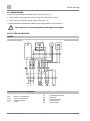
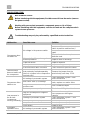
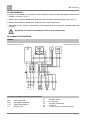
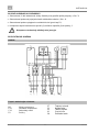
13. ELECTRICAL DIAGRAMS
DK50 B
1/N/PE~230 V, 50/60 Hz
ELEKTRIC OBJECT OF 1st. CAT.
Description to electrical diagrams:
M1
EV1
YV1
FU
Motor of compressor
Fan of compressor
Solenoid valve
Fuses
ST
C1
SP
X1
PH
Temperature switch
Capacitor
Pressure switch
Terminal box
Hour counter

OPERATION
06/2023 17 NP-DK50 B-A-2_06-2023
OPERATION
ONLY TRAINED PERSONNEL MAY OPERATE THE EQUIPMENT!
Risk of electric shock.
In case of emergency, disconnect the compressor from the mains (pull out the
mains plug).
Burn or fire hazard.
Portions of the air pump may be hot and reach hazardous temperatures during
compressor operation that may harm materials or operating staff.
Warning – compressor is controlled automatically.
Automatic start-up. When pressure in the pressure tank drops to switch-on
pressure, the compressor automatically switches on. The compressor
automatically switches off, when pressure in the air tank reaches the switch-off
pressure.
Potential for damage to pneumatic components.
The working pressure settings for the pressure switch set by the manufacturer
cannot be changed. Compressor operation at a working pressure below the
switching pressure indicates high air usage (see the Troubleshooting chapter).
During prolonged operation of the compressor, the ambient temperature around
the compressor may increase to over 40 °C. At this point the cooling fan
automatically switches on. The fan switches off once the space is cooled to
around 32 °C.

OPERATION
NP-DK50 B-A-2_06-2023 18 06/2023
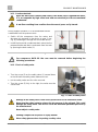
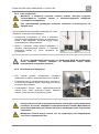
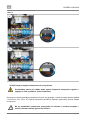
14. SWITCHING ON THE COMPRESSOR
Fig. 5: Switching the compressor
Switch on the compressor at the pressure switch (1) by turning the knob (2) to position “I.” The
compressor sends pressurized air to the air tank. As the compressed air is used, the pressure in
the air nozzle drops to a preset level, the compressor switches on and the air nozzle files with
compressed air. After reaching the cut-off pressure the compressor turns off automatically and the
cycle is repeated. Check the value of switching-on and switching-off pressure on pressure gauge
(3). The values may be within a tolerance of 10%. Air pressure in air chamber must not exceed
maximal permitted operation pressure.
Risk of damage to pneumatic parts.
The pressure switch (1) was set up by the manufacturer and any other changes
to it settings may be performed only by a qualified technician trained by the
manufacturer.
15. SWITCHING OFF THE COMPRESSOR
• Switching off the compressor due to service or any other reason shall be performed using the
pressure switch (1) by turning the switch (2) to position „0“ and pulling out the mains plug from
the socket. This disconnects the compressor from the mains supply.(Fig. 5)
• Vent the pressure in the air tank to zero by opening the drain valve.

PRODUCT MAINTENANCE
06/2023 19 NP-DK50 B-A-2_06-2023
PRODUCT MAINTENANCE
16. PRODUCT MAINTENANCE
The operator should carry out device checks regularly in the intervals defined by
applicable regulations. Test results must be recorded.
The equipment has been designed and manufactured to keep maintenance to a minimum. The
following work must be performed to preserve the proper and reliable operation of the compressor.
Unauthorised interference hazard.
Repair work outside the framework of standard maintenance (see Chapter 16.1)
may only be performed by a qualified technician (an organisation authorized by
the manufacturer) or the manufacturer’s customer service.
Standard maintenance work (see Chapter 16.1) may only be performed by the
operator’s trained personnel.
Only use manufacturer-approved replacement parts and accessories.
Danger of injury or equipment damage.
Prior to commencing compressor maintenance, it is necessary to:
- check if it is possible to disconnect the compressor from the appliance in
order to avoid any risk of injury to the person using the appliance or other
material damage;
- turn off the compressor;
- disconnect it from the mains (pulling the cord out of the mains socket);
- vent the compressed air from the air tank.
Venting compressed air poses an injury hazard.
Wear eye protection, i.e. goggles, when venting compressed air from the
compressed air circuit (air tank) and from the dryer chamber.
Burn hazard.
Pump components (head, cylinder, pressure hose) have high temperature during
and shortly after compressor operation – do not touch these components!
Let the device cool before any product maintenance, service or connection/
disconnection of pressurized air!

PRODUCT MAINTENANCE
NP-DK50 B-A-2_06-2023 20 06/2023
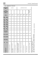
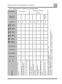
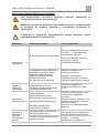
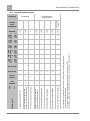
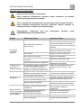
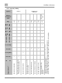
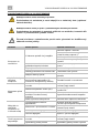
16.1. Maintenance intervals
Performed
by
operator
qualified technician
a) data is in hours, if not available, data is in years
b) applies to compressor without dryer
c) time interval reduces by 20% for compressor variants 60 Hz
(2000h./1600h., 4000h./3200h., 6000h./4800h., 8000h./6400h., 10000h./8000h., 12000h./9600h.)
Set of
replacement
parts
-
-
-
-
-
-
-
025200126-
000
Chap.
16.2
16.5
7
16.3
16.4
16.8
16.6
16.7
12000
hours
9600
hours
x
10000
hours
8000
hours
8000
hours
6400
hours
x
6000
hours
4800
hours
4000
hours
3200
hours
x
2000
hours
1600
hours
Once every
2 years
x
Once a year
x
x
x
x
Once a week
x
Once a day
x
x
50 Hz
60 Hz
Check of product operation
Drain condensate from air tank b) – at
high humidity
Check of product function
Check of pneumatic connections
leakage and device inspection
Inspection of electrical connections
Check of cooler and fan
Check of safety valve
Replacement of pump inlet filter a)
Time interval c)
Strona się ładuje...
Strona się ładuje...
Strona się ładuje...
Strona się ładuje...
Strona się ładuje...
Strona się ładuje...
Strona się ładuje...
Strona się ładuje...
Strona się ładuje...
Strona się ładuje...
Strona się ładuje...
Strona się ładuje...
Strona się ładuje...
Strona się ładuje...
Strona się ładuje...
Strona się ładuje...
Strona się ładuje...
Strona się ładuje...
Strona się ładuje...
Strona się ładuje...
Strona się ładuje...
Strona się ładuje...
Strona się ładuje...
Strona się ładuje...
Strona się ładuje...
Strona się ładuje...
Strona się ładuje...
Strona się ładuje...
Strona się ładuje...
Strona się ładuje...
Strona się ładuje...
Strona się ładuje...
Strona się ładuje...
Strona się ładuje...
Strona się ładuje...
Strona się ładuje...
Strona się ładuje...
Strona się ładuje...
Strona się ładuje...
Strona się ładuje...
Strona się ładuje...
Strona się ładuje...
Strona się ładuje...
Strona się ładuje...
Strona się ładuje...
Strona się ładuje...
Strona się ładuje...
Strona się ładuje...
Strona się ładuje...
Strona się ładuje...
Strona się ładuje...
Strona się ładuje...
Strona się ładuje...
Strona się ładuje...
Strona się ładuje...
Strona się ładuje...
Strona się ładuje...
Strona się ładuje...
Strona się ładuje...
Strona się ładuje...
Strona się ładuje...
Strona się ładuje...
Strona się ładuje...
Strona się ładuje...
Strona się ładuje...
Strona się ładuje...
Strona się ładuje...
Strona się ładuje...
Strona się ładuje...
Strona się ładuje...
Strona się ładuje...
Strona się ładuje...
Strona się ładuje...
Strona się ładuje...
Strona się ładuje...
Strona się ładuje...
Strona się ładuje...
Strona się ładuje...
Strona się ładuje...
Strona się ładuje...
Strona się ładuje...
Strona się ładuje...
Strona się ładuje...
Strona się ładuje...
-
 1
1
-
 2
2
-
 3
3
-
 4
4
-
 5
5
-
 6
6
-
 7
7
-
 8
8
-
 9
9
-
 10
10
-
 11
11
-
 12
12
-
 13
13
-
 14
14
-
 15
15
-
 16
16
-
 17
17
-
 18
18
-
 19
19
-
 20
20
-
 21
21
-
 22
22
-
 23
23
-
 24
24
-
 25
25
-
 26
26
-
 27
27
-
 28
28
-
 29
29
-
 30
30
-
 31
31
-
 32
32
-
 33
33
-
 34
34
-
 35
35
-
 36
36
-
 37
37
-
 38
38
-
 39
39
-
 40
40
-
 41
41
-
 42
42
-
 43
43
-
 44
44
-
 45
45
-
 46
46
-
 47
47
-
 48
48
-
 49
49
-
 50
50
-
 51
51
-
 52
52
-
 53
53
-
 54
54
-
 55
55
-
 56
56
-
 57
57
-
 58
58
-
 59
59
-
 60
60
-
 61
61
-
 62
62
-
 63
63
-
 64
64
-
 65
65
-
 66
66
-
 67
67
-
 68
68
-
 69
69
-
 70
70
-
 71
71
-
 72
72
-
 73
73
-
 74
74
-
 75
75
-
 76
76
-
 77
77
-
 78
78
-
 79
79
-
 80
80
-
 81
81
-
 82
82
-
 83
83
-
 84
84
-
 85
85
-
 86
86
-
 87
87
-
 88
88
-
 89
89
-
 90
90
-
 91
91
-
 92
92
-
 93
93
-
 94
94
-
 95
95
-
 96
96
-
 97
97
-
 98
98
-
 99
99
-
 100
100
-
 101
101
-
 102
102
-
 103
103
-
 104
104


EKOM DK50 B Instrukcja obsługi
- Kategoria
- Sprężarki powietrza
- Typ
- Instrukcja obsługi
w innych językach
- slovenčina: EKOM DK50 B Používateľská príručka
Powiązane artykuły


Inne dokumenty
-
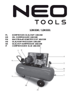 NEO TOOLS 12K031 Instrukcja obsługi
-
 NEO TOOLS 12K030 Instrukcja obsługi
-
Schneider Airsystems UNM 240-8-40 WXM Clean Original Operating Manual
-
Schneider Airsystems Universal 170-25 W Original Operating Manual
-
 G de 551-10-100 3 Cylinder Compressor Instrukcja obsługi
-
Parkside 285200 Operation and Safety Notes
-
Scheppach HC24 o Original Instruction Manual
-
Parkside PKO 400 B2 Operation and Safety Notes
-
Scheppach HC06 Translation Of Original Instruction Manual
-
Parkside PKO 270 B2 Operation and Safety Notes


