
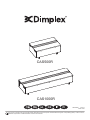
CAS1000R
The product complies with the European Safety Standards and the European Standard Electromagnetic Compatibility (EMC). These cover the
essential requirements of EMC Directives and the LVD Directive.
08/53963/0 Issue 2
OCN 11034
CAS500R

2
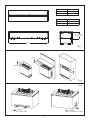
Dim A 300mm
Dim B
Min: 190mm
Max: 260mm
MODEL DIM ‘A’
CAS500R 508mm
CAS1000R 1017mm
FUEL BED DIM ‘B’
METAL 304mm
LOG 354mm
>210cm
2
Eg. 42cm x 5cm
>210cm
2
Eg. 14.5cm x 14.5cm
Fig.2
Fig.3
Fig.1
400mm
400mm
400mm

L
N
E
>420cm
2
Eg. 84cm x 5cm
Fig.4
>420cm
2
Eg. 20.5cm x 20.5cm
Fig.5
Fig.6
Fig.6B
Fig.6A
Fig.7
>420cm
2
Eg. 84cm x 5cm
>420cm
2
Eg. 84cm x 5cm

Fig.10
Fig.8
Fig.9
Fig.11
Fig.12A
CAS500R
CAS1000R

Fig.13
Fig.12B
Fig.14
Fig. 15
Fig. 16
Fig. 17

Fig. 18
Fig. 19
Fig. 20
Fig. 19A
Fig. 19B

Fig 21
Fig 22
Fig 24
CAS1000
CAS500
A
Fig 25
B
C
D
Fig 23
Fig 26
Fig 27

GB ................................................................................................ 1
DE ................................................................................................ 9
NL ............................................................................................... 17
FR .............................................................................................. 25
IT ................................................................................................. 33
PL ............................................................................................... 41

1
Dimplex CAS500R, CAS1000R
Introduction
Please read this information guide carefully to be able to safely install, use and maintain your product.
When using electrical appliances, basic precautions should always be followed to reduce the
risk of re, electrical shock and injury to persons, including the following:
If the appliance is damaged, check with the supplier before installation and operation.
Do not use outdoors.
Do not use in the immediate surroundings of a bath, shower or swimming pool.
Do not locate the appliance immediately below a xed socket outlet or connection box.
This appliance can be used by children aged from 8 years and above and persons with reduced
physical, sensory or mental capabilities or lack of experience and knowledge if they have been
given supervision or instruction concerning use of the appliance in a safe way and understand
the hazards involved. Children shall not play with the appliance. Cleaning and user maintenance
shall not be made by children without supervision.
Children of less than 3 years should be kept away unless continuously supervised.
Children aged from 3 years and less than 8 years shall only switch on/off the appliance provided
that it has been placed or installed in its intended normal operating position and they have been
given supervision or instruction concerning use of the appliance in a safe way and understand
the hazards involved. Children aged from 3 years and less than 8 years shall not plug in,
regulate and clean the appliance or perform user maintenance.
CAUTION: Some parts of this product can become very hot and cause burns. Particular
attention has to be given where children and vulnerable people are present.
Do not use this appliance in series with a thermal control, a program controller, a timer or any
other device that switches on the heat automatically, since a re risk exists when the heater is
accidentally covered or displaced.
Ensure that furniture, curtains or other combustible material are positioned no closer than 1
meter from the appliance.
In the event of a fault unplug the appliance.
Unplug the appliance when not required for long periods.
Although this appliance complies with safety standards, we do not recommend its use on deep
pile carpets or on long hair type of rugs.
The appliance must be positioned so that the plug is accessible.
If the supply cord is damaged it must be replaced by the manufacturer or service agent or a
similarly qualied person in order to avoid a hazard.
Keep the supply cord away from the front of the appliance.
WARNING: In order to avoid overheating, do not cover the appliance. Do not place material or
garments on the appliance, or obstruct the air circulation around the appliance.
The appliance carries a DO NOT COVER warning symbol.
This appliance is not equipped with a device to control the room temperature. Do not use this
appliance in small rooms when they are occupied by persons not capable of leaving the room
on their own, unless constant supervision is provided.

2
General Information
Installation Instructions
This section describes how to install and set up your re.
Before you start:
Ensure that all packing items are removed (read any warning labels carefully) and retain all packing for possible future
use.
Before connecting the appliance, check that the supply voltage is the same as that stated on the appliance.
CONNECTIONS REQUIRED IN ADVANCE OF INSTALLATION
Electrical Connection
Please ensure a 240V / 13A power socket is located within 1m of the product. The electrical connection should be
accessible during product installation so that the connection can be made to the product easily.
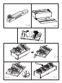
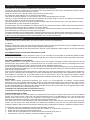
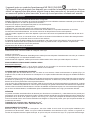
BUILDING THE PRODUCT SURROUND/ENCLOSURE
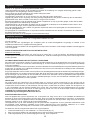
This product can be built into a wall, surround or structure. Please take note of the product dimensions (Fig.1) and build
your wall, surround or structure accordingly. Suitable clearance should be provided to allow the product to be installed
easily.
You are required to leave a minimum of 400mm from the base of the fuel bed to any shelf/enclosure above the product
(Fig. 2). This will allow enough space above the product to allow the ame effect to form fully and not to be obstructed.
When determining a location for the product, ensure that the unit will not be susceptible to drafts, vents, ceiling fans and
other air currents. Similar to a candle, large movements of air will affect the unit’s ability to create and maintain the ame
effect. If the desired location is susceptible to signicant air movement, i.e. air vents, the different installation options
illustrated in Fig 2 can be used.
VENTILATION
This product needs free ventilation from underneath to operate correctly. There are slots on the underside of the product
to allow this free air through the product. The free ventilation helps keep the electronic components cool and allows the
mist to rise and leave the product. Please see Fig 3 & 4 for examples of the required ventilation. Please take note of the
requirement for a ventilation opening on the shelf where the product sits, to allow a clear path for the air to get to the
product.
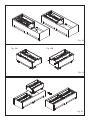
CAS500R Free Ventilation Area: Minimum 210cm
2
CAS1000R Free Ventilation Area: Minimum 420cm
2
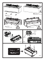
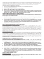
ELECTRICAL CONNECTION
Plug the re into a 13amp/240 Volt outlet. Be sure to have access to the plug after installation to allow for disconnection.
Ensure that the supply cable exits at the back of the re at the right or left hand corner to suit your supply socket location
and is not trapped under the re such that it might cause it to be damaged.
The appliance can be connected to the xed wiring of the premises through a suitable connection box positioned
adjacent to the appliance. This electrical installation must be carried out by a competent electrician and be in strict
accordance with the current I.E.E regulations for Electrical Equipment in Buildings.
The electrician can remove the supplied plug by the following;
1. Lift off the fuelbed and put switch ‘A’ into the off position (Fig 21).
2. Ensure that the appliance is unplugged.
Only use ltered/decalcied water in this appliance.
Unpack the appliance carefully and retain the packaging for possible future use, in the event of moving or returning
the re to your supplier.
Always ensure that the appliance is sitting on a level surface.
The appliance is a ame effect only.
The appliance is designed to be built into a surround or built into a wall.
Please note: Used in an environment where background noise is very low, it may be possible to hear a sound which is
related to the operation of the ame effect. This is normal and should not be a cause for concern.
Once installed, never move this appliance or lay on its back, without draining the water from sump and water tank.
The water tank, sump, sump lid, tank cap and air lters must be cleaned once every 2 weeks, particularly in hard
water areas.
If you intend not using the appliance for longer than 2 weeks, drain the water from sump and water tank and dry the
sump.
The sump and the water tank in this product are treated with a biocidal product, Silver Biocide. This conforms to the
latest relevant ISO standard
Do not drink the water from the sump or from the water tank(s).

3
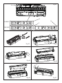
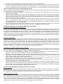
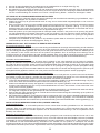
3. Lift off the access cover by removing the retaining screw (Fig 5).
4. Unscrew and remove the Live, Neutral and Earth wires (Fig 6A)
5. Unscrew the cable clamp (Fig 6B) and remove the supply cord.
6. The electrician can then connect the wire from the appliance to the connection box (by following the steps above in
reverse) ensuring that it incorporates a double pole isolating switch, having a contact separation of at least 3mm.
Brown - Live (L), Blue - Neutral (N) and Green/Yellow - Earth (E)
INSTALLING THE PRODUCT INTO SURROUND/ENCLOSURE
Once your enclosure has been built to the required dimensions and the electrical connection has been installed, follow
the steps below to install your product.
1. Sit the product on the constructed base, ensuring the cable is accessible and not caught under the product.
2. Ensure the product is at the correct height to suit the installation and ensure it is adequately level. This can be done
by adjusting the adjustable feet with a at head screwdriver. (Fig 7) The levelness of the product can be veried by
checking the on-board spirit level which is located on the metal base towards the back of the re (Fig 8).
3. Once the product is at the correct height and is level, centre the product within the opening. If using the LED log fuel
bed (which is wider than the product), this can be done by tting the fuel bed to the product. The fuel bed will centre
itself within the opening and its guides will centre the product underneath (Fig 9).
4. With the product in its nal position, remove the fuel bed and screw the product to the surround using the four xing
holes shown in Fig 10.
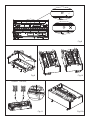
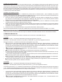
COMMISSIONING/INITIAL PRODUCT START-UP
Connecting the Receiver/Tethered Remote
With the fuel bed removed, insert the 3.5mm jack of the Bluetooth receiver into the socket at the back of the appliance
(Fig 11). It is important to ensure that the jack is pushed fully into the socket. Failure to fully insert the jack will prevent
the product from functioning correctly. The receiver has a cable length of 1.4m which will allow you position it anywhere
around the product. If you prefer to hide it, the receiver can be placed inside the surround/wall. Please ensure that the
receiver is not enclosed in metal, concrete or any other dense material, this will affect the signal from the remote control.
Filling the Water Tank
Before powering on the product for the rst time, ensure that a full water tank has been placed on the product. Remove
the water tank from its location on top of the sump (Fig 12A) and open it by unscrewing the orange cap (Fig 12B). The
tank should be lled with ltered/decalcied water only. When the tank is replaced on top of the sump, it will take about
one minute for the tank to empty into the sump. Allow the sump to ll fully before switching on the product. Once lling
is complete, the tank can be relled and replaced on top of the sump. This will allow for the maximum capacity of water
to be stored in the product.
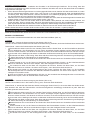
Installing the Log Fuel Bed (If Supplied)
The product is supplied with a ‘metal fuel bed’ tted. If you have chosen to operate your product with a log fuel bed,
remove this metal fuel bed and retain it for future use (Fig. 13). Follow the steps below to install the log fuel bed.
1. Gently lift the LED Log fuel bed out of its packaging. CAUTION: The fuel bed weighs 5kg. Be sure to only lift the fuel
bed by the two centre logs (Fig. 14).
2. Place the fuel bed on top of the appliance, there are 4 plastic guides under the fuel bed to help locate it (Fig.9).
Please note the fuel bed can be placed front to back or back to front on the product.
3. Once the fuel bed is in place, remove the small loose log (Fig 15). This small log is secured with magnets and should
easily lift off the fuel bed.
4. Locate the DC jack under the small log and connect it to the corresponding DC jack located on the product through
the hole in the fuel bed (Fig.16).
5. Each log fuel bed is supplied with a loose non LED log. For single CAS500R installations, this can be placed on top
of the fuel bed or stored away with the packaging. For CAS1000R or multiple product installations, the loose log can
be placed on the centre join between two fuel beds (Fig 17).
MULTIPLE PRODUCT INSTALLATION (DAISY CHAINING)
Power Connections
Both the CAS500R and CAS1000R products can be installed side by side to elongate the ame effect. When supplying
power to multiple products, ensure the maximum wattage of the combined products does not exceed the rated capacity
of the MCB (Minature Circuit Breaker) in the circuit.
Multiple Product Control
Each product can be paired with its own remote or multiple products can be paired a single remote. Please note a
maximum of six individual products (CAS500R/CAS1000R) can be connected to a single Bluetooth remote control. This
will allow for control of all products at once with a single remote control. Additionally, the software of the product has
been designed in such a way that when multiple products are connected to an external isolating switch, products can be
manually switched off and when switched back on they will operate in the same state as before they were switched off.

4
This section describes how to activate your re using either the manual controls or remote control.
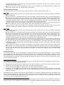
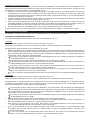
MANUAL CONTROLS
The manual controls are located beneath the fuel bed. (Fig 21)
CAS500R
Mains Switch - Controls the electricity supply to the appliance. (Fig 21A)
Note: This switch must be in the ‘ON’ ( I ) position for the appliance to operate
Button Panel - Controls the functioning of the appliance. (Fig 21B)
• is the on/standby button. Press it to turn on and off the ame effect. Turning it on will be indicated by a single
beep and the main LED lights activating. Be careful not to look directly into the LED’s as they can be very bright.
Although the main LED lights operate immediately, a further 45 seconds of warm up time is required before the
ame effect starts.
• is the Pairing button. This will pair your remote control to the receiver. See ‘Remote Control Operation’ for details.
• is the test mode button. This will be used by the manufacturer and the Service Engineer.
• is the reduce ame button. Press this to reduce the height/intensity of your ame. You will hear an audible beep
when you reach the minimum level.
• is the increase ame button. Press this to increase the height/intensity of your ame. You will hear an audible
beep when you reach the maximum level.
• is the reduce re crackling sound. Press this to reduce the volume of the crackling sound. The minimum volume
for this is off. You will hear an audible beep when you reach the minimum level
• is the increase re crackling sound. Press this to increase the volume of the crackling sound.You will hear an
audible beep when you reach the maximum level.
CAS1000R
Mains Switch - Controls the electricity supply to the appliance. (Fig 21A)
Note: This switch must be in the ‘ON’ ( I ) position for the appliance to operate
Button Panel ‘C’ Controls the functioning of the left side of product while Button Panel ’D’ controls the functioning of the
right side of the product. Please note the ame height and re crackling noise can be controlled independently on each
individual side of the product.
• is the on/standby button. Press it to turn on and off the ame effect. Turning it on will be indicated by a single
beep and the main LED lights activating. Be careful not to look directly into the LED’s as they can be very bright.
Although the main LED lights operate immediately, a further 45 seconds of warm up time is required before the
ame effect starts.
• is the pairing button. This will pair your remote control to the receiver. See ‘Remote Control Operation’ for details.
• is the test mode button. This will be used by the manufacturer and the Service Engineer.
• is the reduce ame button. Press this to reduce the height/intensity of your ame. You will hear an audible beep
when you reach the minimum level
• is the increase ame button. Press this to increase the height/intensity of your ame. You will hear an audible
beep when you reach the maximum level.
• is the reduce re crackling sound. Press this to reduce the volume of the crackling sound. The minimum volume
for this is off. You will hear an audible beep when you reach the minimum level.
• is the increase re crackling sound. Press this to increase the volume of the crackling sound. You will hear an
audible beep when you reach the maximum level.
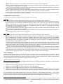
Operating the Product
Multiple Product Installation
Follow steps 1-4 in “Installing the Product into Surround/Enclosure” to t the rst product. It is important that the rst
product is orientated so that the side of the product with the slots is left free and not connected to rst end of the
installation (Fig 18).
1. When the rst product is installed and securely xed, prepare the second product by unscrewing the joining screws
(Fig 19A) and screwing them into the opposite side of the metalwork (Fig 19B). Please note, these screws should
not be fully tightened and 5-10mm of thread should be left protruding from the edge of the product.
2. Fit the second product beside the rst product, ensuring the protruding screws of the second product engage with
slots of the rst product. (Fig 20)
3. Ensure the second product is at the correct height to match the rst product and ensure it is adequately level. This
can be done by adjusting the adjustable feet with a at head screwdriver. (Fig 8) The levelness of the product can
be veried by checking the on-board level (Fig 9)
4. Tighten the screws of the second product so that it joins tightly with the rst product.
Additional products can be tted to the second product by following steps 1-4 above.

5
RECEIVER CONTROLS
The product can also be controlled using the receiver which is supplied with the product. (Fig 12)
CAS500R
• is the on/standby button. Press it to turn on and off the ame effect.
• is used to mute the re crackling sound. Press this to turn on and off the crackling sound. The volume can be
adjusted on the manual controls of the appliance. Please note that the mute setting will not be saved after a product
restart. The crackling sound can be turned off completely by using the volume control buttons on the button panel to
reduce the volume to its minimum setting. This minimum setting will be remembered after a product restart.
• is the reduce ame button. Press this to reduce the height/intensity of your ame. You will hear an audible beep
when you reach the minimum level.
• is the increase ame button. Press this to increase the height/intensity of your ame. You will hear an audible
beep when you reach the maximum level
CAS1000R
• is the on/standby button. Press it to turn on and off the ame effect.
• is used to mute the re crackling sound. Press this to turn on and off the crackling sound. The volume can be
adjusted on the manual controls of the appliance. Please note that the mute setting will not be saved after a product
restart. The crackling sound can be turned off completely by using the volume control buttons on the button panel to
reduce the volume to its minimum setting. This minimum setting will be remembered after a product restart.
• is the reduce ame button. Press the reduce ame button on the second button row to reduce the height/intensity
of the ame on the left hand side of the product. Press the reduce ame button on the third button row to reduce
the height/intensity of the ame on the right hand side of the product. You will hear an audible beep when you reach
the minimum level.
• is the increase ame button. Press the increase ame button on the second button row to increase the height/
intensity of the ame on the left hand side of the product. Press the increase ame button on the third button row to
increase the height/intensity of the ame on the right hand side of the product. You will hear an audible beep when
you reach the maximum level.
REMOTE CONTROL
The remote control is supplied with 2xAAA batteries. Remove the battery cover from the underside of the remote control
and after removing the batteries from the plastic wrapping t them into place. Replace the battery cover. With the product
powered off, a functional test can be carried out on the remote control by pushing any button and observing the blue LED
at the top o the remote ashing with each button push.
Pairing the Remote Control
The remote control has wireless Bluetooth technology and needs to be paired to the receiver. This can be done by
following the steps below.
1. Press the rocker switch to the on (I) position; a single beep will be heard.
2. Press the button on the Button Panel; the product will turn on.
3. Press the button on the Button Panel, the LED’s will start to slowly blink on and off.
4. Press the button on the remote control; the product LEDs will ash quickly three times and the product will then
automatically switch off. The remote control is now paired to the product and can be used to switch it back on.
The operation of the remote control is the same as described in ‘Receiver Controls’. You can pair multiple products to the
one remote control by repeating the pairing operation as above on your subsequent products. Please note a maximum
of six CAS500R/CAS1000R products can be paired to the one remote control.
Pairing the Remote Control to Multiple Products
If you are installing multiple CAS500R/CAS1000R products you can pair them to a single remote control. To do this,
please install the products as described in the “Installation Instructions”. Ensure that all products are connected to mains
power and have water supplied. If you are pairing CAS1000R and CAS500R products please choose the 6 button
remote control as the master remote control.
1. Pair the rst product as described in steps 1-4 above.
2. On your second product, press the rocker switch to the on (I) position; a single beep will be heard.
3. Press the button on the Button Panel; the product will turn on.
4. Press the button on the Button Panel, the LED’s will start to slowly blink on and off.
5. Press the button on the remote control; the LEDs will ash quickly three times and the product will then
automatically switch off. The remote control is now paired to the two products and can be used to switch them on.
6. Repeat the above steps to pair the next product.

6
GENERAL TIPS
Only use ltered/decalcied water in this appliance.
Always ensure that the appliance is sitting on a level surface.
If you intend not using the appliance for longer than 2 weeks, remove and empty the sump and water tank.
Once installed, never move this appliance or lay on its back, without draining the water from sump.
CLEANING
Warning – Always press Switch ‘A’ to the ‘OFF’ (0) position (Fig 21) and disconnect from the power supply before
cleaning the re.
We recommend cleaning the following components once every 2 weeks, particularly in hard water areas:
Sump, Nozzle, Tank cap and seal, Air lter
For general cleaning use a soft clean duster – never use abrasive cleaners.
To remove any accumulation of dust or uff, the soft brush attachment of a vacuum cleaner should occasionally be used.
Sump
1. Press Switch ‘A’ to the ‘OFF’ (0) position (Fig 21)
2. Gently lift off the fuel bed and place it aside.
3. Remove the water tank from its position on top of the sump.
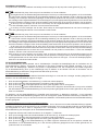
4. Disconnect the electrical connector to the transducers, located on the right side of the sump. (Fig 23).
5. There are two orange clips holding down the nozzle on the sump; one on the left and one on the right hand side of
the nozzle. On the left side, press in the clip with one hand and with the other lift the nozzle out of the clip. Repeat
this for the right side (Fig 24). The nozzle can now be lifted up and placed aside (Fig 25).
6. Gently lift up the sump (Fig 26), taking care to keep it level so as not to spill any water. Sit the sump in the sink.
7. Carefully empty the sump into the sink taking note that the transducer is held in place by a retaining clip.
Maintenance
7. When all products are paired, test the remote control by pressing the button. If any of the products fail to receive
a signal from the remote control you can bring that product back in line with the others via the Manual Controls or
the receiver controls.
GETTING THE DESIRED FLAME EFFECT
1. Switch the appliance on by pressing the main switch to the on position and pressing the button. The ames will
start after 45seconds.
2. Press the and buttons to adjust the ame to your desired level. Please give the ame generator time to react
to the changes you make.
Once you have made your adjustments to both the ame height and crackling sound, the appliance will keep these
settings even if you power off the appliance by either the on/standby button or by the main switch. The next time you
switch on the appliance, it will start up as normal, wait 45 seconds for the ames to start and then revert to the adjusted
settings.
Nozzle Inserts
Nozzle inserts have been supplied and tted to the nozzle opening. These inserts are used to alter the prole of the
ame effect. These inserts can be removed if a different ame prole is preferred. In addition to these inserts, inserts for
blocking the ame in certain areas have also been supplied. To t these inserts, remove the exisitng inserts that have
been supplied and tted to the product. Break the blocking inserts into the required length. Snap the inserts into the
nozzle opening in the desired location. See Fig 22 for further deatils.
LOW WATER / REFILLING THE WATER TANKS
When the water tanks have emptied and the water level in the product is getting low, the product will ash its LEDs twice
and beep twice. The product will operate for a further 15 minutes before beeping once and switching into low water
mode. For products being operated with the LED log fuel bed, the fuel bed will remain illuminated while in low water
mode. At this point, the product can either be switched into stand-by mode using the remote control or Bluetooth receiver
or the product can be relled with water. Relling the product with water will cause the product to restart automatically.
To rell the tank, remove the fuel bed and remove the water tank from its position on top of the sump. Rell the water tank
using ltered/decalcied water only. The tank can then be replaced on top of the sump. If the product was not switched
into stand-by mode after experiencing low later, the product will restart automatically after about 20 seconds of relling.
Please note that for a CAS1000R product, the side of the product that is experiencing low water will ash twice and beep
twice. The water tanks on both sides of the CAS1000R product can be relled at this point as it is likely that they should
both be empty or near empty.

7
AFTER SALES SERVICE
Your product is guaranteed for two years from the date of purchase. Within this period, we undertake to repair or
exchange this product free of charge (excluding transducer discs & subject to availability) provided it has been installed
and operated in accordance with these instructions. Your rights under this guarantee are additional to your statutory
rights, which in turn are not affected by this guarantee.
RECYCLING
For electrical products sold within the European Community - At the end of the electrical products useful life
it not be disposed of with household waste. Please recycle where facilities exist. Check with your Local
Authority or retailer for recycling advice in your country.
PATENT / PATENT APPLICATION
Products within the Optimyst range are protected by one or more of the following patents and patent applications:
Great Britain GB2460259B, GB2475794B, GB2418014, EP2029941, GB2436212, GB2402206B
United States US8413358, US8136276, US7967690, US8574086
Russia RU2434181
European EP2029941, EP2315976, EP1787063 (A1), EP2388527, EP2029941,
China CN101883953A, CN102105746A, CN101057105 (A), CN101438104
Australia AU2009248743A1, AU2007224634
Canada CA2725214, CA2579444, CA2645939
South Africa ZA2008/08702
Mexico MX2008011712
South Korea KR101364191
Japan JP5281417, JP5496291
Brazil BRP10708894
India 4122/KOLNP/2008
New Zealand NZ571900
8. Put a small amount of washing up liquid into the sump, and using a soft brush, gently clean all surfaces in the sump
and gently clean the transducer including the cone and metal discs located in the top grooved surface.
9. When cleaned, thoroughly rinse the sump with clean water to remove all traces of washing up liquid.
10. Clean the nozzle with a soft brush and ush out thoroughly with water.
11. Reverse the above steps 1 – 6 to reassemble.
Transducer
The transducer is a consumable item and may need to be replaced through time, depending on its usage. Replacement
transducers can be purchased from our your dealer. The transducer is xed in the sump with a plastic clip. If you need
to replace your transducer:
1. Follow the steps 1-5 in the CLEANING - Sump section under ‘Maintenance’ to gain access to the transducer.
2. Press the clip back and lift the transducer upwards out of its holder.
3. Place the new transducer into the sump, ensuring the its cable does not sit over the cone.
4. Reverse the above steps to reassemble the nozzle and sump.
Air Filter
1. Gently lift out the fuel bed and place it aside.
2. Gently slide the air lter upwards out of its plastic holder. (Fig 27)
3. Gently rinse with water in the sink and dry with fabric towel.
4. Replace the lter making sure that the coarse black lter is facing outwards.
5. Replace the fuel bed.
Additional Information

8
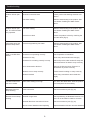
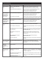
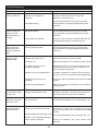
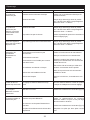
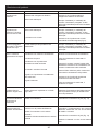
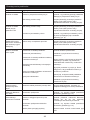
Symptom Cause Corrective Action
Product will not oper-
ate.
Electrical connection issue
Low water reading
Ensure product has working electrical con-
nection.
Rell the water tank(s) of the product. See
“Low Water / Relling the Water Tanks”
above.
Product will not oper-
ate. The LED fuel bed
only operates.
Low water reading
Product is not level
Rell the water tank(s) of the product. See
“Low Water / Relling the Water Tanks”
above.
Ensure the product is level by checking the
on-board level (Fig 8).
LEDs blink twice and
product beeps twice
Product is approaching low water Rell the water tank(s) of the product. See
“Low Water / Relling the Water Tanks”
above.
Little or No Mist Gen-
eration
Transducer not operating correctly
Transducer is dirty
Transducer is not sitting correctly in sump
Fan is obstructed or blocked
Nozzle is not on sump correctly
Nozzle is blocked
Check operation of transducer
Clean sump and transducer thoroughly
Switch off product, take nozzle off sump and
ensure transducer is tted in sump correctly
Remove air lter and clean. Ensure it is
placed back in product correctly.
Ensure Nozzle is sitting on sump correctly
Clean sump, transducer and nozzle thor-
oughly
The ame effect has
too much smoke.
Flame effect setting is too high Turn down the ame effect. Give the product
time to adjust to the new setting
Bluetooth Receiver
stops working
Loose connection Check connection to jack (Fig 12)
Remote Control stops
working
Bluetooth range issue
Bluetooth Receiver connection is loose
Remote control batteries need replacing
Check positioning of Bluetooth Receiver. En-
sure it is not encased in metal or concrete.
Check connection to jack (Fig 12)
Replace batteries with two new AAA batteries
Troubleshooting

9
Dimplex CAS500, CAS1000
Wichtiger Sicherheitshinweis
Einleitung
Lesen Sie diese Informationen bitte sorgfältig, damit Sie das Gerät sicher installieren und warten können.
Wenn Sie elektronische Geräte verwenden, sollten Sie stets grundlegende
Sicherheitsvorkehrungen treffen, um die Gefahr von Feuer, einem elektrischen Schlag und
Verletzungen zu vermeiden. Dazu zählen:
Ist das Gerät beschädigt, sprechen Sie vor der Installation und Inbetriebnahme unverzüglich
mit dem Lieferanten.
Nicht draußen verwenden.
Nicht in unmittelbarer Umgebung von Badewannen, Duschen oder Schwimmbecken verwenden.
Nicht unter einer xen Steckdose oder einer Anschlussbox stellen.
Dieses Gerät darf von Kindern benutzt werden, die acht Jahre oder älter sind und reduzierte
körperliche, sensorische und geistige Fähigkeiten bzw. mangelnde Erfahrung aufweisen,
wenn sie dies unter Aufsicht oder Anleitung tun und sie über die möglichen Gefahren bei der
Benutzung dieses Geräts aufgeklärt wurden. Kinder dürfen mit diesem Gerät nicht spielen. Die
Reinigung und Wartung dieses Geräts durch Kinder darf nicht ohne Aufsicht erfolgen.
Kinder, die jünger als drei Jahre sind, sollten von diesem Gerät ferngehalten werden, wenn sie
nicht unter permanenter Aufsicht sind.
Kinder im Alter zwischen drei und acht Jahren dürfen das Gerät nur an- und ausschalten,
wenn es in seiner vorgesehenen normalen Betriebsposition aufgestellt und installiert wurde
und sie Anweisungen für den sicheren Betrieb des Gerätes erhalten haben und die potentiellen
Gefahren verstehen. Kinder zwischen drei und acht Jahren dürfen das Gerät nicht einstecken,
reinigen oder Wartungsarbeiten durchführen.
WARNUNG: Einige Teile dieses Geräts können sehr heiß werden und Verbrennungen verursachen.
Besondere Aufmerksamkeit ist geboten, wenn Kinder und gefährdete Personen anwesend sind.
Das Gerät nicht zu einer Wärmeregelung, einer Programmsteuerung, einer Zeitschaltuhr oder
einem anderen Gerät in Reihe schalten, mit dem die Wärmequelle automatisch geschaltet
wird. Bei versehentlicher Blockierung oder Verstellung des Heizgeräts besteht Brandgefahr.
Stellen Sie sicher, dass sich Möbel, Vorhänge oder andere brennbare Materialien nicht näher
als 1 Meter vom Gerät benden.
Sollte ein Fehler auftreten, bitte das Gerät ausstecken.
Stecken Sie das Gerät aus, wenn es längere Zeit nicht benutzt wird.
Obwohl dieses Gerät den Sicherheitsstandards entspricht, empfehlen wir, das Gerät nicht auf
Hochor-Teppichen oder auf Teppichen mit langen Fasern zu benutzen.
Das Gerät muss so platziert werden, dass der Stecker zugänglich ist.
Wenn das Stromkabel beschädigt ist, muss es durch den Hersteller oder einen Servicetechniker
oder eine ähnlich qualizierte Person ersetzt werden, um Gefahrenquellen auszuschließen.
Halten Sie das Stromkabel vom vorderen Teil des Geräts fern.
WARNUNG: Um Überhitzung zu vermeiden das Gerät nicht abdecken. Keine Materialien oder
Textilien auf das Gerät legen oder den Luftuss um das Gerät herum beeinträchtigen.
Das Gerät trägt ein Warnetikett mit der Aufschrift: NICHT BEDECKEN.
Dieses Gerät besitzt keine Raumtemperaturkontrolle. Verwenden Sie das Gerät nicht in kleinen
Räumen, wenn die Personen im Raum nicht in der Lage sind, den Raum selbst zu verlassen,
es sei denn, sie werden stets beaufsichtigt.

10
Allgemeine Informationen
Installationsanleitung
In diesem Abschnitt wird beschrieben, wie Sie Ihren Kamin einrichten und installieren.
Vor Beginn:
Stellen Sie bitte sicher, dass alle Verpackungsmaterialien entfernt wurden (Warnkennzeichnungen sorgfältig lesen) und
bewahren Sie die Verpackung für eine mögliche Wiederverwendung auf.
Vor Anschluss des Geräts an das Stromnetz prüfen Sie bitte, ob die Voltzahl der Zahl entspricht, die auf dem Heizgerät
angegeben ist.
NOTWENDIGE ANSCHLÜSSE VOR DER INSTALLATION
Elektrische Anschlüsse
Stellen Sie sicher, dass sich eine Steckdose mit 240 V (13 A) innerhalb von einem Meter im Umfeld des Geräts bendet.
Der Stromanschluss sollte während der Installation zugänglich sein, sodass die Verbindung leicht hergestellt werden kann.
BAU DES RAHMENS/DES GEHÄUSES
Dieses Produkt kann in eine Wand, einen Rahmen oder eine Struktur eingebaut werden. Bitte beachten Sie die
Abmessungen des Produkts (Abb.1) und konstruieren Sie Ihre Wand oder Ihren Rahmen dementsprechend. Eine
entsprechende Reinigung sorgt dafür, dass das Gerät einfach installiert werden kann.
Es ist notwendig, mindestens einen Abstand von 400 mm von der Basis des Brennstoffbetts zu einem Regal/Gehäuse
oberhalb des Geräts einzuhalten (Abb. 2). Das ermöglicht ausreichend Platz, sodass sich der Flammeffekt voll entfalten
kann und er nicht gestört wird.
Wenn Sie einen Standort für das Gerät festlegen, stellen Sie sicher, dass das Gerät keinem Luftzug, keinen Ventilatoren
oder anderen Luftströmungen ausgesetzt ist. Große Luftbewegungen beeinträchtigen die Fähigkeit des Geräts, den
Flammeffekt zu erzeugen und zu erhalten (ähnlich wie bei einer Kerze). Wenn der gewünschte Standort großen
Luftbewegungen ausgesetzt ist, können die abgeänderten Installationsanweisungen wie in Abb. 2 verwendet werden.
BELÜFTUNG
Dieses Gerät benötigt ausreichend Belüftung (von unten), um ordnungsgemäß zu arbeiten. Einlassschächte
benden sich an der Unterseite des Produkts, damit Luft durch das Gerät strömen kann. Dieser freie Luftzug hilft den
Komponenten dabei abzukühlen und sorgt dafür, dass der Nebel aus dem Gerät entweichen kann. Siehe Abb. 3 und 4
für die notwendige Belüftung. Beachten Sie, dass das Regal, auf dem das Produkt steht, eine Lüftungsöffnung erfordert,
damit Luft problemlos zum Produkt gelangen kann.
CAS500R Freier Belüftungsbereich: Minimum 210 cm
2
CAS1000R Freier Belüftungsbereich: Minimum 420 cm
2
ELEKTRISCHE ANSCHLÜSSE
Stecken Sie den Kamin in eine Steckdose mit 13 Ampere/240 Volt. Achten Sie darauf, dass Sie nach der Installation
Zugang zum Stecker haben, damit Sie das Gerät ausstecken können. Das Netzkabel muss an der Rückseite des
Kamins rechts oder links in der Ecke auf möglichst kurzem Wege zur Steckdose austreten und darf nicht unter dem
Kamineinsatz eingeklemmt werden, da es hierdurch beschädigt werden kann.
Das Gerät kann an die feste Verkabelung der Räumlichkeiten mittels einer kleinen Anschlussdose angeschlossen
werden, die sich neben dem Gerät bendet. Die elektrische Installation muss von einem professionellen Elektriker
ausgeführt werden. Dabei müssen die aktuellen Bestimmungen zu elektrischen Geräten in Gebäuden befolgt werden.
Der Elektriker kann den mitgelieferten Stecker folgendermaßen entfernen:
1. Heben Sie das Brennstoffbett ab und setzen Sie den Schalter „A“ in die Position OFF (Abb. 21).
2. Stellen Sie sicher, dass das Gerät ausgesteckt ist.
3. Heben Sie den Zugangsdeckel ab, indem Sie die Fixierschraube lösen (Abb. 5).
4. Aufschrauben und Leiter, Nullleiter und Masse entfernen (Abb. 6A)
Verwenden Sie für das Gerät nur geltertes bzw. entkalktes Leitungswasser.
Packen Sie das Gerät sorgfältig aus und bewahren Sie die Verpackung für den Fall auf, dass Sie das Gerät zu Ihrem
Lieferanten bringen oder zurückschicken müssen.
Stellen Sie immer sicher, dass das Gerät auf einer ebenen Fläche steht.
Es handelt sich dabei lediglich um ein Gerät mit Flammeffekt.
Das Gerät ist darauf ausgelegt, in einen Rahmen oder in eine Wand eingebaut zu werden.
Hinweis: In leisen Umgebungen ist ein hörbares Geräusch des Geräts möglich, welches vom Betrieb des Flammenef-
fekts herrührt. Dies ist normal und stellt kein Problem dar.
Nach der Installation dürfen Sie das Gerät niemals bewegen oder auf den Rücken legen, ohne das Wasser aus dem
Sammelbehälter und dem Wassertank abzulassen.
Der Wassertank, der Sammelbehälter, der Wannendeckel, der Tankdeckel und die Luftlter müssen alle zwei Wochen
gereinigt werden, insbesondere in Gebieten mit hartem Wasser.
Wenn Sie das Gerät länger als zwei Wochen nicht benutzen, lassen Sie das Wasser aus dem Sammelbehälter und
dem Wassertank ab und trocknen Sie den Sammelbehälter.
Der Sammelbehälter und der Wassertank in diesem Produkt sind mit dem Biozidprodukt Silberbiozid behandelt, um
schädliche oder unerwünschte Organismen zu bekämpfen. Dies entspricht dem neuesten einschlägigen ISO-Standard.
Trinken Sie nicht das Wasser aus dem Sammelbehälter oder aus den Wassertanks.

11
5. Schrauben Sie die Kabelklemme auf (Abb. 6B) und entfernen Sie das Stromkabel.
6. Der Elektriker kann anschließend das Kabel des Geräts mit der Anschlussdose verbinden (indem er oben genannte
Schritte in umgekehrter Reihenfolge durchführt) und sicherstellen, dass ein doppelpoliger Isolierschalter vorhanden
ist, der eine Kontakttrennung von mindestens 3 mm aufweist. Braun - Leiter, Blau (Nullleiter) und Grün/Gelb (Masse)
INSTALLATION DES PRODUKTS IM RAHMEN/GEHÄUSE
Wenn Ihr Gehäuse dann die richtigen Abmessungen aufweist und alle Elektroarbeiten abgeschlossen sind, befolgen Sie
diese Schritte, um Ihr Gerät zu installieren.
1. Setzen Sie das Produkt auf die Basis auf und stellen Sie sicher, dass alle Kabel zugänglich sind und sie sich nicht
unter dem Gerät benden.
2. Stellen Sie sicher, dass sich das Gerät auf der passenden Höhe bendet, und achten Sie darauf, dass es gerade
steht. Mit einem Schraubenzieher können Sie die verstellbaren Füße anpassen. (Abb. 7) Sie können überprüfen,
ob das Gerät gerade steht, indem Sie auf die integrierte Wasserwaage blicken, die auf dem Metallsockel in hinteren
Bereich des Kamins zu nden ist (Abb. 8).
3. Wenn sich das Gerät auf der korrekten Höhe bendet und gerade steht, zentrieren Sie das Gerät mit der Öffnung.
Wenn Sie das LED-Brennstoffbett verwenden (es ist breiter als das Gerät), kann dies erreicht werden, indem Sie
das Brennstoffbett an das Gerät anpassen. Das Brennstoffbett positioniert sich innerhalb der Öffnung und die
Führung zentriert es unten von selbst (Abb. 9).
4. Wenn sich das Gerät in der nalen Position bendet, entfernen Sie das Brennstoffbett und schrauben Sie das Gerät
an die Einrahmung, indem Sie die vier Fixierlöcher, die in Abb. 10 gezeigt werden, verwenden.
KOMMISSIONIERUNG / ERSTE INBETRIEBNAHME DES GERÄTS
Verbindung des Empfänger/der Fernsteuerung
Stecken Sie nach Entfernung des Brennstoffbetts den 3,5-mm-Stecker des Bluetooth-Empfängers in den Anschluss auf
der Rückseite des Geräts (Abb. 11). Es ist wichtig, dass der Stecker vollständig in die Steckdose gesteckt wird. Wenn
der Stecker nicht vollständig eingesteckt wird, kann es sein, dass das Produkt nicht ordnungsgemäß funktioniert. Der
Empfänger hat eine Kabellänge von etwa 1,4 Metern, wodurch er an beliebiger Stelle im Umfeld des Geräts positioniert
werden kann. Wenn Sie ihn lieber verstecken möchten, kann der Empfänger auch in der Wand/Einfassung platziert
werden. Stellen Sie bitte sicher, dass der Empfänger nicht von Metall, Beton oder anderen dichten Materialien umgeben
ist. Das beeinträchtigt nämlich das Signal.
Füllen des Wassertanks
Bevor Sie das Produkt zum ersten Mal einschalten, müssen Sie sicherstellen, dass es über einen vollen Wassertank
verfügt. Entfernen Sie den Wassertank von seiner Position über dem Sammelbehälter (Abb. 12A) und öffnen Sie ihn,
indem Sie den orangen Deckel abschrauben. Der Tank darf ausschließlich mit geltertem/entkalktem Wasser gefüllt
werden. Wenn Sie den Tank wieder auf dem Sammelbehälter platzieren, dauert es etwa eine Minute, bis sich der
Tank in den Sammelbehälter entleert. Warten Sie, bis sich der Sammelbehälter vollständig gefüllt hat, bevor Sie das
Produkt einschalten. Im Anschluss an die Füllung können Sie den Tank wieder auffüllen und auf dem Sammelbehälter
platzieren. So lässt sich im Produkt die maximale Menge an Wasser aufbewahren.
Installation des Log-Brennstoffbetts (falls vorhanden)
Das Produkt wird mit einem Brennstoffbett aus Metall geliefert. Wenn Sie sich dazu entschieden haben, das Gerät mit
einem Scheitholzbett zu betreiben, entfernen Sie das Brennstoffbett aus Metall und heben Sie es für die Zukunft auf
(Abb. 13). Folgen Sie den Anweisungen, um das Scheitholzbett zu installieren.
1. Heben Sie das LED-Scheitholzbett sorgfältig aus der Verpackung. WARNUNG: Das Brennstoffbett wiegt 5
Kilogramm. Heben Sie das Brennstoffbett nur an den zwei Mittelblöcken an (Abb. 14).
2. Setzen Sie das Brennstoffbett oben auf das Gerät; es gibt vier Plastikführungen unter dem Brennstoffbett, die Ihnen
dabei helfen, es richtig zu platzieren (Abb. 10). Bitten beachten Sie, dass das Brennstoffbett mit der vorderen oder
hinteren Seite auf das Produkt aufgesetzt werden kann.
3. Wenn das Brennstoffbett korrekt sitzt, entfernen Sie den kleinen, losen Klotz (Abb. 15). Dieser kleine Klotz ist mit
Magneten xiert und sollte sich leicht aus dem Brennstoffbett entfernen lassen.
4. Suchen Sie nach der DC-Buchse unter dem kleinen Klotz und verbinden Sie sie mit dem DC-Anschluss auf dem
Produkt durch das Loch im Brennstoffbett (Abb. 16).
5. Jedes Scheitholzbett ist mit einem losen LED-Scheitholz ausgestattet. Für einfache CAS500R-Installationen kann
dieses oben auf dem Brennstoffbett platziert werden oder gemeinsam mit der Verpackung weggeräumt werden.
Bei CAS1000R- oder mehrfachen Produktinstallationen kann dieses lose Scheitholz auf der mittleren Verbindung
zwischen den beiden Brennstoffbetten platziert werden (Abb. 17).
INSTALLATION MEHRERER PRODUKTE (DURCHSCHLEIFEN)
Stromanschlüsse
Die Produkte CAS500R und CAS1000R können gemeinsam installiert werden, um den Flammeffekt zu vergrößern.
Wenn Sie mehrere Produkte gemeinsam betreiben, stellen Sie sicher, dass die gemeinsame Wattzahl aller Geräte nicht
die vorgesehene Kapazität des Miniaturtrennschalters im Stromkreis übersteigt.
Steuerung mehrerer Produkte
Jedes Gerät kann mit seiner eigenen Fernsteuerung betrieben werden. Es ist aber auch möglich, mehrere Geräte mit
einer Fernsteuerung zu bedienen. Achten Sie bitte darauf, dass maximal sechs einzelne Geräte (entweder CAS500R
oder CAS1000R) mit einer Bluetooth-Fernsteuerung betrieben werden können. Somit können alle Geräte gleichzeitig
mit nur einer Fernsteuerung betrieben werden. Die Software des Produkts wurde derart entwickelt, dass, wenn mehrere
Geräte an einem externen Trennschalter hängen, die Geräte manuell abgeschaltet werden können. Wenn sie wieder
aktiviert werden, arbeiten sie auf die gleiche Art und Weise wie vor dem Abschalten.

12
Dieser Abschnitt beschreibt, wie Sie das Feuer entweder durch manuelle Bedienung oder mit der Fernsteuerung aktivieren.
MANUELLE STEUERUNG
Die manuellen Kontrollelemente benden sich neben dem Brennstoffbett. (Abb. 21)
CAS500R
Hauptschalter – Steuert die Stromversorgung des Geräts. (Abb. 21A)
Hinweis: Hinweis: Dieser Schalter muss sich auf der Position EIN ( I ) benden, damit das Gerät betrieben werden kann.
Tasten-Panel - Steuert die Funktionsweise des Geräts. (Abb. 21B)
• Es handelt sich dabei um die Ein- bzw. Standby-Taste. Drücken Sie die Taste, um den Flammeffekt zu aktivieren
und zu deaktivieren. Das Einschalten wird von einem einmaligen Piepton begleitet und die Haupt-LED-Lichter
leuchten. Achten Sie drauf, nicht direkt in die LEDs zu schauen, da sie sehr hell leuchten können. Die LED-Lampen
leuchten zwar sofort, allerdings sind weitere 45 Sekunden Aufwärmzeit notwendig, bevor der Flammeffekt startet.
• Es handelt sich dabei um die Pairing-Taste. Dies stellt eine Verbindung zwischen Fernsteuerung und Empfänger
her. Siehe „Benutzung der Fernsteuerung“ für weitere Details.
• Dabei handelt es sich um die Taste für den Testmodus. Diese Funktion wird vom Hersteller und Servicetechniker
verwendet.
• Hierbei handelt es sich um die Taste zum Reduzieren des Flammeffekts. Drücken, um die Höhe/Intensität der
Flamme zu reduzieren. Sie hören einen Piepton, wenn das niedrigste Level erreicht wurde.
• Es handelt sich dabei um die Taste zum Vergrößern der Flamme. Drücken Sie diese Taste, um die Höhe/
Intensität der Flamme zu erhöhen. Sie hören einen Piepton, wenn die höchste Stufe erreicht ist.
• Es handelt sich hierbei um das Knistergeräusch des Feuers. Drücken Sie diese Taste, um die Lautstärke
des Knistergeräusches zu reduzieren Die Minimal-Lautstärke ist deaktiviert. Sie hören einen Piepton, wenn das
niedrigste Level erreicht wurde.
• dient zum Erhöhen der Knisterlautstärke. Drücken, um die Lautstärke des Knistergeräusches zu erhöhen.Sie
hören einen Piepton, wenn die höchste Stufe erreicht wurde.
CAS1000R
Hauptschalter – Steuert die Stromversorgung des Geräts. (Abb. 21A)
Hinweis: Der Schalter muss in der Position „EIN“ (I) sein, damit das Gerät funktioniert.
Tasten-Panel „C“ steuert die linke Seite des Geräts, wohingegen Tasten-Panel „D“ die rechte Seite des Geräts steuert.
Bitte beachten Sie, dass die Flammenhöhe und das Knistergeräusch unabhängig voneinander an jeder Seite des
Produkts gesteuert werden können.
• Es handelt sich dabei um die Ein- bzw. Standby-Taste. Drücken Sie die Taste, um den Flammeffekt zu aktivieren
und zu deaktivieren. Das Einschalten wird von einem einmaligen Piepton begleitet und die Haupt-LED-Lichter
leuchten. Achten Sie drauf, nicht direkt in die LEDs zu schauen, da sie sehr hell leuchten können. Die LED-Lampen
leuchten zwar sofort, allerdings sind weitere 45 Sekunden Aufwärmzeit notwendig, bevor der Flammeffekt startet.
• Es handelt sich dabei um die Pairing-Taste. Dies stellt eine Verbindung zwischen Fernsteuerung und Empfänger
her. Siehe „Benutzung der Fernsteuerung“ für weitere Details.
• Dabei handelt es sich um die Taste für den Testmodus. Diese Funktion wird vom Hersteller und Servicetechniker
verwendet.
• Hierbei handelt es sich um die Taste zum Reduzieren des Flammeffekts. Drücken, um die Höhe/Intensität der
Flamme zu reduzieren. Sie hören ein akustisches Signal, wenn das niedrigste Niveau erreicht wurde.
• Es handelt sich dabei um die Taste zum Vergrößern der Flamme. Drücken Sie diese Taste, um die Höhe/
Intensität der Flamme zu erhöhen. Sie hören einen Piepton, wenn die höchste Stufe erreicht ist.
• Es handelt sich hierbei um das Knistergeräusch des Feuers. Drücken Sie diese Taste, um die Lautstärke
Bedienung des Produkts
Installation mehrerer Produkte
Folgen Sie den Schritten 1-4 in „Installation des Produkts in der Einfassung/im Gehäuse“. Es ist wichtig, dass das
erste Gerät so aufgestellt wird, dass die Seite mit den Schächten frei bleibt und nicht an das erste Ende der Installation
angeschlossen wird (Abb. 18).
1. Wenn das erste Gerät angeschlossen und ordnungsgemäß xiert wurde, bereiten Sie das zweite Gerät vor, indem
Sie die Verbindungsschrauben lockern (Abb. 19A) und sie in die gegenüberliegende Seite des Metallgehäuses
schrauben (Abb. 19B). Bitte beachten, dass die Schrauben nicht vollständig angezogen werden sollten und 5-10
mm des Gewindes aus dem Gehäuse des Geräts herausragen sollten.
2. Verbinden Sie nun das erste Gerät mit dem zweiten und stellen Sie sicher, dass die herausragenden Schrauben des
zweiten Geräts in die Schächte des ersten Geräts greifen. (Abb. 20)
3. Stellen Sie sicher, dass sich das zweite Gerät in der korrekten Höhe passend zum ersten Produkt bendet, und
sorgen Sie dafür, dass es gerade steht. Mit einem Schraubenzieher können Sie die verstellbaren Füße anpassen.
(Abb. 8) Die Ebenheit des Produkts kann mit der integrierten Wasserwaage überprüft werden (Abb. 9)
4. Ziehen Sie die Schrauben des zweiten Produkts an, damit es fest mit dem ersten Gerät verbunden ist.
Weitere Geräte können am zweiten Gerät montiert werden, indem Sie die Schritte 1-4 (oben) befolgen.
Strona się ładuje...
Strona się ładuje...
Strona się ładuje...
Strona się ładuje...
Strona się ładuje...
Strona się ładuje...
Strona się ładuje...
Strona się ładuje...
Strona się ładuje...
Strona się ładuje...
Strona się ładuje...
Strona się ładuje...
Strona się ładuje...
Strona się ładuje...
Strona się ładuje...
Strona się ładuje...
Strona się ładuje...
Strona się ładuje...
Strona się ładuje...
Strona się ładuje...
Strona się ładuje...
Strona się ładuje...
Strona się ładuje...
Strona się ładuje...
Strona się ładuje...
Strona się ładuje...
Strona się ładuje...
Strona się ładuje...
Strona się ładuje...
Strona się ładuje...
Strona się ładuje...
Strona się ładuje...
Strona się ładuje...
Strona się ładuje...
Strona się ładuje...
Strona się ładuje...
-
 1
1
-
 2
2
-
 3
3
-
 4
4
-
 5
5
-
 6
6
-
 7
7
-
 8
8
-
 9
9
-
 10
10
-
 11
11
-
 12
12
-
 13
13
-
 14
14
-
 15
15
-
 16
16
-
 17
17
-
 18
18
-
 19
19
-
 20
20
-
 21
21
-
 22
22
-
 23
23
-
 24
24
-
 25
25
-
 26
26
-
 27
27
-
 28
28
-
 29
29
-
 30
30
-
 31
31
-
 32
32
-
 33
33
-
 34
34
-
 35
35
-
 36
36
-
 37
37
-
 38
38
-
 39
39
-
 40
40
-
 41
41
-
 42
42
-
 43
43
-
 44
44
-
 45
45
-
 46
46
-
 47
47
-
 48
48
-
 49
49
-
 50
50
-
 51
51
-
 52
52
-
 53
53
-
 54
54
-
 55
55
-
 56
56


Dimplex CAS 500R Instrukcja obsługi
- Typ
- Instrukcja obsługi
w innych językach
- italiano: Dimplex CAS 500R Manuale del proprietario
- Deutsch: Dimplex CAS 500R Bedienungsanleitung
- français: Dimplex CAS 500R Le manuel du propriétaire
- English: Dimplex CAS 500R Owner's manual
- Nederlands: Dimplex CAS 500R de handleiding
Powiązane artykuły
Inne dokumenty
-
Tristar AT-5464 Instrukcja obsługi
-
Sea Ray 2007 44DA Parts Manual
-
-
-
-
-
Stovax Radiance Inset Electric Fires User Instructions
-
-
Lumi WC0112 Instrukcja obsługi
-
Garmin Portable echo Instrukcja obsługi