
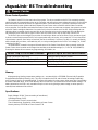
MENU
CANCEL
BACK
FORWARD
ENTER
SPA AUX 1
AUX 4
AUX 2
AUX 5
AUX 3
AUX 6
POOLHEATERS
AUX 7
SPA SOL AR
DISPLAY HOLD/RELEASE
®
Troubleshooting Manual

TABLE OF CONTENTS
Equipment Layout . . . . . . . . . . . . . . . . . . . . . . .
Controller . . . . . . . . . . . . . . . . . . . . . . . . . . . . . .
Power Center . . . . . . . . . . . . . . . . . . . . . . . . . . .
Power Center (continued) . . . . . . . . . . . . . . . . .
Standard Relay . . . . . . . . . . . . . . . . . . . . . . . . .
Two-Speed Relay . . . . . . . . . . . . . . . . . . . . . . .
Light Dimming Relay . . . . . . . . . . . . . . . . . . . . .
Jandy Valve Actuator . . . . . . . . . . . . . . . . . . . . .
Sensors . . . . . . . . . . . . . . . . . . . . . . . . . . . . . . .
DIP Switches . . . . . . . . . . . . . . . . . . . . . . . . . .
TeleLink RS . . . . . . . . . . . . . . . . . . . . . . . . . . .
Spa Side Switch . . . . . . . . . . . . . . . . . . . . . . . .
Glossary of Terms. . . . . . . . . . . . . . . . . . . . . . .
Quick Check List . . . . . . . . . . . . . . . . . . . . . . .
Quick Check List (continued) . . . . . . . . . . . . . .
Controller Inoperable, Display Blank . . . . . . . .
All Lights Lit on Controller . . . . . . . . . . . . . . . .
Some Controller Buttons Do Not Operate . . . .
Three Amp Fuse Keeps Failing . . . . . . . . . . . .
Heater Doesn't Fire . . . . . . . . . . . . . . . . . . . . .
Wiring Diagram for AquaLink RS
Dual Equipment RS2/6, 2/10, 2/14 . . . . . . .
Wiring Diagram for AquaLink RS
Combos and Onlys, RS4, 6, 8, 12, 16 . . . .
1
2
3
4
5
6
7
8
9
10
11
12
13
14
15
16
17
18
19
20
21
22
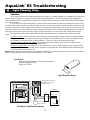
This is the Troubleshooting Manual for the AquaLink RS line of electronic controllers. Use it as
a tool to solve problems with the AquaLink RS Control Systems. Please follow all local, state and
national codes when installing or servicing electronic equipment, and please refer to all warning
decals and notices before proceeding with any troubleshooting.
AquaLink
®
RS Troubleshooting
Table of Contents

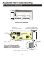
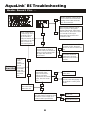
Intake
JVA
Return
JVA
Filter
Pump
Pool Filter
Pool Heater
TM
Pool Water Sensor
2
5
7
OPTIONAL
IMPORTANT:
Plug in Orange 3-pin
connector from Transformer
to P.C.B.
8
2
5
6
6
3
4
6
AquaLink
®
RS Troubleshooting
Equipment Layout
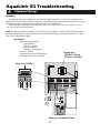
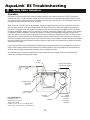
1

Operation:
The Indoor Controller serves as a means of entering and viewing information for equipment settings. All
programs, labels, etc., are held in a memory chip on the Power Center Printed Circuit Board. Power is not
required to maintain programs, etc. - they will be held indefinitely.
The Controller is supplied 10 VDC from the power center via the outside two wires (red and green) of the
4 conductor cable. The inner two wires (yellow and black) provide the communication link between the
Controller PCB and Power Center PCB.
If either of the communication wires are broken ("open circuit"), but the power supply wires are connected,
the display screen will indicate a break in communication by displaying the controller part number and the
version letter of the Micro Controller (e.g., 6543 REV B01 or 6700 REV C).
Pressing the Reset button, located on the left side of the Indoor Controller, will momentarily display the
software part numbers and revision letters for both the Controller's Micro-controller chip and the Power
Center's PPD chip. The Reset button also resets the Micro-controller, but does not remove any programming,
AUX labels, etc. (see chart on Page 16 for list of Part Numbers).
Time/Date Backup: Supplied by 9-volt battery located at Power Center
Programming and Memory Backup: Stored in EEPROM on Power Center PCB, stored indefinitely,
even with no power to unit.
NOTE: A Jandy Service Controller (P.N. 7057)
can be attached out at the Power Center, to review
and/or change programs and equipment settings.
Controller Specifications:
Supply Voltage: 10 VDC
Operating Voltage: 5 VDC
Circuit Activation: Serial Communication
TM
Co
ntr
o
ll
e
r
Reset Switch
Access Hole
B
ac
k Vi
e
w
o
f
Co
ntr
o
ll
e
r
Controller (back view)
Yellow
Green
Black
Red
4321
Delay Override Switch
PCB
Display Module
J
umpers
f
or
Multiple Controller
Reset
Switch
Micro Controller
Chart of Multiple Controllers
Jumper Settin
g
s
Controller 1
W2
W1
Controller 3
W2
W1
Controller 4
W2
W1
W2
Controller 2
W1
AquaLink
®
RS Troubleshooting
1 Controller
2

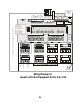
Power Center Operation:
The Power Center PCB is the true brain of the system. The micro-controller on the PCB is constantly sending
signals through the communication wires to the Controller and polling the system to determine which circuits should
be on and which should be off. When an equipment button, such as Auxiliary 1, is pressed, impulses are sent via
the communication wires (yellow and black) between Power Center micro-controller and the Indoor Controller
micro-controller. If all impulses received at the Power Center micro-controller are consistent, the system then looks
at the DIP Switch settings to determine if an option for this circuit has been set. If the DIP Switch settings do not
indicate a delay is needed, signals are sent back to the Controller to turn on the appropriate LED and display the
ON message. At the same time, a signal is sent to one of the two Driver Chips on the Power Center PCB.
The Driver Chips can be thought of as a series of small relays. When one of the Driver Chips receives a signal,
it closes a contact which passes 24 VDC to the appropriate relay coil socket, in this case AUX 1. Each relay driver
chip activates a specific set of relay coil sockets (see the chart below). If a Driver Chip fails, it is usually caused by
either shorted relay coil wires, a shorted relay coil, or a relay not designed for the 24 VDC coil voltage (i.e., 24 VAC
rather than 24 VDC).
The Reset button, located in the upper left hand corner of the Power Center Bezel, when pressed, resets the
Power Center micro-controller and changes time and date to the default settings (i.e., 1:00 P.M. 01/31/96 WED).
Pressing this button will not remove any programming, AUX labels, etc.
Memory:
All programming, labeling, temperature settings, etc., are stored within a EEPROM (Electronically Eraseable
Programmable Read Only Memory) chip. This chip is located on the PCB and will retain all settings indefinitely,
even if power is lost for an extended period. To remove information from the system, either press the Cancel button
to remove individual items, or the Clear Memory item from the Menu, to reset all items to their default settings. The
battery attached to the PCB is only needed to keep the clock running during a power outage, so when power is
restored, time and date will be correct.
Specifications:
Supply Voltage: 24 VAC (from secondary of transformer)
Operating Voltage: 5 VDC
Circuit Activation: Serial Communication
Time / Date backup: Supplied by 9 Volt battery at Power Center
Memory backup: EEPROM on Power Center PCB
Driver Chip in U9 socket activates: Driver Chip in U10 socket activates:
Relay Socket for Filter Pump
Relay Socket for Auxiliaries 1 throu
g
h 7
Relay Socket for Spare Auxiliary
Relay Socket for Electric Heater
Solar Booster Pump Socket
All JVA Relay Coils
Low Volta
g
e Heater Relay Coil
AquaLink
®
RS Troubleshooting
2 Power Center
3

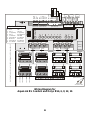
Back View Of Power Center Board
24 VAC from
Secondary of Transformer
3 Amp Fuse
Relay Driver Chips
Jumper for Freeze Protection
with Solar on Dual Equipment Models
Programmable Peripheral Device
Spare Aux
pry slots
alignment arrow
be
v
e
l
ed
co
rn
e
r
U9 Socket
U10 Socket
SPARE AUX -
This socket has power only when the Filter
Pump is on and the pool water is circulating.
It has no power when the system switches to
“Spa”. It is used on a pool/spa combination
system when the user wishes to turn off a piece
of equipment (such as the chlorine generator)
while the spa is being used.
DIP
S
witches
Bezel and Power Center Board
AquaLink
®
RS Troubleshooting
2 Power Center (continued)
4

A Standard Relay's coil is supplied 24 VDC from the Power Center PCB via one of the two driver chips.
When 24 VDC is received by the relay's coil wires, it closes the contacts that complete the circuit to turn on the
equipment (i.e., power supplied to Line 1 goes out Load 1 to the equipment).
Standard Relays may be wired to activate a 110 VAC circuit (e.g., Line 1/Load 1) or a 220 VAC circuit
(e.g., Line 1/Load 1 and Line 2/Load 2).
NOTE: If a relay's coil wires are shorted, or an AC relay coil is plugged into a relay socket, when that circuit is
activated, it will damage one of the two relay Driver Chips (Part No. 3814) on the Power Center PCB. (These
chips can be replaced/see Page 4).
Specification:
Maximum Contact Ratings:
3 hp at 220 VAC
1 1/2 hp at 110 VAC
25 amps - Inductive
1500 watts - Incandescent
Relay Coil: 24 VDC
Resistance across coil: 0.300K Ohms
Amperage draw of coil: 0.10 Amps
Operation:
Wirin
g
for a Standard Rela
y
Relay Coil (24 VDC)
Transformer
120 VAC Primary
24 VAC Secondary
Filter P um p Rela
y
Aux. 3 Rela
y
Optional
Load 2
Line 2
Load 1
Line 1
Optional
Optional
Optional
Wire Nut to
120 VAC Power
Low voltage raceway (do not run high voltage in this compartment)
Breakers
Ground
Neutral
Blower
(110 VAC)
Filter Pump
(220 VAC)
120 VAC
PRIMARY
24 VAC
SECONDARY
Relay
Line 1
Load 1
Line 2
Load 2
AquaLink
®
RS Troubleshooting
5
3 Standard Relays

Operation:
The Two Speed Relay operates in conjunction with a Standard Relay to operate a two speed pump/motor.
The Standard Relay is the On/Off relay and the Two Speed Relay is the switching relay. Activating the relay coil for
the Standard Relay will complete the contact circuit between Line 1 and the motor common, and Line 2 and the Two
Speed Relay's Common. If the Two Speed Relay's coil wires are deactivated, its contacts make connection between
its Common terminal and its Normally Closed terminal and the motor runs at High Speed. When the Two Speed Relay
coil is activated, its contact makes connection between its Common contact and Normally Open contact, and the
motor switches to Low Speed.
If the Two Speed Motor is the filtration pump, plug the relay coil wires for the Standard Relay into the Filter Pump
Relay socket. Next, plug the Two Speed Relay's coil wires into Auxiliary 2. Finally, turn on DIP switch 2 to set circuitry
to two speed operation.
NOTE: Turn off power to system before moving DIP switches.
S
pecifications:
Maximum Contact Ratin
g
s:
2 hp at 220 VAC
1 hp at 110 VAC
Relay Coil: 24 VDC
Resistance across coil: 128 Ohms
Ampera
g
e draw of coil: 0.20 Amps
Wirin
g
for a Two Speed Rela
y
NO
NC
COMMON
Filter
Pump
HIGH
COM
LOW
240
VAC
Two Speed Relay
Standard Relay
T
O
FILTER PUMP
SOCKET
TO AUX 2
SOCKET
(2 H.P. Maximum)
AquaLink
®
RS Troubleshooting
4 Two Speed Relay
6

Operation:
The Controller signals the Light dimming Relay to turn ‘fully on”, “partially dimmed”, or “completely off” by sending a
specific number of pulses in a set period of time to the Light Dimming Relay. The circuitry of the Light Dimming Relay
(which requires 120 VAC to operate) then interprets the number and timing of pulses to determine whether the light should
be on, off, or dimmed.
The circuitry of the Light Dimming Relay is driven by the 120 VAC power from the circuit breaker for the light. Unlike
a Standard Relay, which receives a constant 24 VDC to its coil to hold the relay contacts closed (and which opens when that
voltage is removed), the Light Dimming Relay receives only signal pulses on the relay coil wires, and it is the circuitry on the
relay that actually turns on, off, and dims the light. Therefore, if the light is full on or dimmed, unplugging the relay coil wires
to the Light Dimming Relay will not turn off the light. The light will remain on as long as 120 VAC is supplied to the relay.
The Light Dimmer will operate slightly differently when activated from the Controller, Power Center or Spa Side
Switch.
From the Controller - When the auxiliary, which has been assigned to light dimming is pressed or programmed on,
the light will turn on to the brightness last set by pressing Back or Forward Buttons. Once on, the brightness may
be changed by pressing the Back or Forward Buttons. To turn it off, press the auxilliary button again.
From the Power Center override switch - Pressing the appropriate auxilliary button will turn the light on to the
brightness last set at the Controller or Spa Side Switch.
From the Spa Side Switch - If a button on the Spa Side Switch has been programmed to control a Light Dimmer
auxilliary, the first press of this button will turn the light on to full brightness, each additional press will dim the light
in 25% increments until the light is off.
Note: Besides needing a Light Dimming Relay installed, the auxilliary to operate the light dimming circuit must be assigned
at the Controller using the Menu button and moving to the SETUP Menu.
AquaLink
®
RS Troubleshooting
4 Light Dimming Relay
7
Specification:
Maximum Contact Ratings : 1000 watts incandescent
Operating Voltage: 120 VAC
Relay Coil : 24 VDC
Installation Intructions - Jand
y
p/n 6587 or 6785
GFCI
NEUTRAL
LIGHT HOT
LIGHT
SUB PANEL
120 v. Breaker
Neutral Bar
LOAD
LINE
Incandescent only.
1000 watts, max.
Wiring for Light Dimming Relay
Standard Rela
y
ma
y
be
pi
ggy
backed on top of
Dimmer Rela
y
Li
g
ht Dimmin
g
Rela
y

Operation:
One leg of a 24 VAC transformer secondary supplies voltage to the common terminal of a SPDT (single-pole,
double-throw) relay. The NC (normally closed) terminal of that relay is connected to the red wire of the JVA cord,
and the NO (normally open) terminal is connected to the white wire of the JVA cord. The completion of the circuit
is through the black (common) wire of the JVA cord.
When the coil of the SPDT relay is de-energized, voltage is supplied from one leg of the transformer secondary
to the common terminal of the relay and then down the red wire of the JVA cord to the toggle switch at the rear
of the JVA. The toggle switch then routes the voltage to either the lower microswitch (toggle in AUTO 1 position),
the upper microswitch (toggle in AUTO 2 position), or to neither microswitch (toggle in OFF position). If the voltage
is routed to the lower microswitch, and that microswitch is closed, the voltage passes through the motor to the
black wire and then back to the other leg of the transformer secondary to complete the circuit. The motor will then
rotate clockwise, turning the gear train (and ultimately the output shaft) until the lower cam comes in contact with
the lower microswitch, which opens the circuit and stops the motor. If the voltage is routed to the upper microswitch,
the motor rotates in the opposite direction until the upper cam lobe comes into contact with the upper microswitch,
which stops the rotation.
If the coil of the SPDT relay is energized, the voltage travels through the white wire to the toggle switch, which as
above, routes it either to the lower microswitch for clockwise rotation or upper microswitch for counterclockwise
rotation, with the voltage traveling back the black wire to complete the circuit.
The capacitor, which is wired in parallel with the motor, keeps the motor rotating in the correct direction and
insures the JVA rotates with the proper torque.
JVA
S
pecifications:
Volta
g
e: 24 VAC
Ampera
g
e: 1.0 AMPS
Torque: 180 in/lbs.
Rotation Time: 34 sec. for 180 de
g
rees
Motor Type: Synchronous - Bidirectional
AquaLink
®
RS Troubleshooting
5 Jandy Valve Actuators
8
Toggle Switch
(on-off-on
D.P.D.T.)
M
otor
24 VAC
Lower Microswitch
(clockwise rotation)
Upper
Microswitch
(counter-
clockwise
rotation)
common
normally
closed
Capacitor
35UF - 150V
black
red
white

10K Ohm
Se
n
so
r
S
ensor Resistance Range
C
hart:
At this temperature (degrees F) Resistance should be (Ohms - X 1000)
50 F 19.9 K Ohms (19,900 Ohms)
60 F 15.3 K Ohms
71 F 11.6 K Ohms
80 F 9.3 K Ohms
90 F 7.3 K Ohms
100 F 5.8 K Ohms
104 F 5.3 K Ohms
Sensor
There is only one AquaLink RS temperature sensor. It is used for reading water, air and solar temperatures. The sensor is
described as a 10K RTD (10,000 Ohms - Resistive Temperature Detector) sensor, although the actual resistance will vary
with temperature. Below is a chart which shows how resistance changes as temperature changes.
When measuring resistance across the sensor leads you must remove the sensor from the circuit.
Either disconnect both wires from the terminal bar or remove the terminal bar from the PCB. Then, to test
the Sensor, “0” out your meter and take reading across the sensor.
If a sensor fails, the Controller display will scroll on that sensor “Shorted” (i.e., little or no resistance), or “Open”
(i.e., no continuity).
NOTE: Temperature sensors from other Jandy Control Models cannot be used with the AquaLink RS.
AquaLink
®
RS Troubleshooting
6 Sensor
9

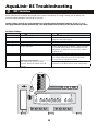
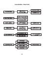
Caution: Always turn off all circuits and then turn off power before moving DIP switches. If AUX 1, 2, or 3
were programmed to operate automatically, clear the programs before turning on the appropriate clip switch.
All DIP Switches are located on the left side of the Power Center Bezel. To change a setting, turn off power, then
move the appropriateswitch from left (off) to right (on).
DIP Switch Settings:
DIP Switch #
Off On
1 Aux 1= any equipment Aux 1 = Pool Cleaner (Pressure Side Cleaner)
2 Aux 2 = any equipment Aux 2 = Low Speed of a two speed pump (filter
pump becomes hi
g
h speed)
3 Aux 3 = any equipment Aux 3 = Spa Spillover effect
4 Heater Cool Down circuit operates Heater Cool Down circuit is disabled
5 Normal operation Factory adjustment for calibration - when this switch
is on heater safety delays are eliminated and solar
temperature is displayed. Don’t leave this switch in
the ON position
6 Normal operation Sharin
g
one heater on Dual Equipment Models
7 Normal operation Allows Cleaner JVA to be assi
g
ned to operate from
an auxiliary; allows air sensor to become Solar
Sensor with Dual Equipment models
8
3
After thermostat settin
g
has been
reached, heater will remain off for
minutes
After thermostat settin
g
has been reached, heater
will remain off for
5
minutes (used for heat pumps)
AquaLink
®
RS Troubleshooting
7 DIP Switches
10

Spa Side Switch buttons send a momentary signal to the Power Center PCB. Each button sends a signal down
one wire with the circuit completed through the common wire. The operation of each button may be tested by
disconnecting the Spa Side Switch from the PCB and with a meter set to continuity measure between each button
wire and the common (black) wire, while holding the button down.
If any button on the Spa Side Switch is held down for more than 5 seconds, the AquaLink RS's microprocessor
considers this a shorted button and will ignore its signal. When the button is released or repaired, and a "shorted
circuit" no longer exists, the microprocessor will again recognize all buttons. The LED in the center of the switch will
be on solid when the spa is on, flashing fast when heating, and flashing slowly when in cool down mode.
Remove the Spa Side Switch (6 pin) terminal bar from the printed circuit board.
Set your meter to read continuity (or resistance ).
• Ensure No Shorts
Measure between the black (common) wire and each of the button wires.
If there is continuity between any of the two (without depressing a button),
the switch is shorted; replace it.
• Ensure Continuity
Do this same test again except this time have a helper hold down the button
while you test for continuity. For example, measure between black and blue
while helper holds down button 1
Black - Common wire
Red - LED wire
Blue - Button 1 wire
Brown - Button 2 wire
White - Button 3 wire
Green - Button 4 wire
Troubleshooting Steps
S
p
a Side Switch
AquaLink
®
RS Troubleshooting
8 Spa Side Switch
11

There are two DIP switches on the TeleLink printed circuit board. DIP switch 1 allows the number of rings before
the TeleLink "picks up" to be set, and DIP switch 2 allows the access code to be changed from the factory default (62).
To change either setting, turn on the DIP switch for the item you wish to change (its LED will light). Next, go to a touch-
tone telephone on the same phone line, lift the receiver and press the button or buttons corresponding to the desired
change (e.g., turn on DIP switch 2 and press telephone buttons 7 and 5 to change access code to 75). Finally, replace
the receiver and turn off the DIP switch. The new setting will now be turned into a memory chip.
The TeleLink printed circuit board has a number of LEDs on it. These LEDs help to identify problems with either the
telephone or the TeleLink (see diagram below). When the TeleLink is operating correctly, LED 2 will be on and LED 12
will be flashing. The four LEDs in the upper left hand corner (5, 6, 7 and 8) indicate whether the TeleLink is receiving the
correct pulse when a button is pressed on the telephone key pad. For example, pressing button 4 on a telephone should
light LED 7. Follow the chart to determine other button/LED operations.
The Diagnostics section of the AquaLink RS menu will indicate if the TeleLink is communicating.
Operation
X
X
X X
X
X X
X X
X X X
X
X X
X X
Phone Cable
from Wall Jack
AquaLink RS
TeleLink Board
To RS485
4-Conductor
Cable
(Cable between
Controller and
Power Center)
red
black
yellow
green
Pro
g
ram
# of rin
g
s
(default: 7)
Pro
g
ram
access code
(default: 62)
12
8
7
6
Key Code
LEDs
LED flashin
g
- system communication
O
K
Second di
g
it of Access Code accepted
First di
g
it of Access Code accepted
Rings
Access
5
LEDs Lit
®
5
6
78
LEDs
Phone
Key
LED li
g
hts up when TeleLink
answers incomin
g
call
LED
g
oes off when phone rin
g
s
LED li
g
hts when button on phone is pressed
1
2
3
4
5
6
7
8
9
0
®
12
11
9
22
1
The chart below indicates
the LED that should li
g
ht
when a button on the
Telephone Key Pad is
pressed, if theTeleLink is
receivin
g
the correct si
g
nal.
AquaLink
®
RS Troubleshooting
TeleLink
12

EEPROM - Electronically Erasable Programmable Read Only Memory
JVA - Jandy Valve Actuator
PCB - Printed Circuit Board
PPD - Programmable Peripheral Device
RTD - Resistive Temperature Detector
VAC - Volts Alternating Current
VDC - Volts Direct Current
AquaLink
®
RS Troubleshooting
Glossary of Terms
13

Symptom
Problem Possible Solution
Power Center override
switches operate when in
Service or Time Out Mode, but
the Controller is completel
y
dead
(
no li
g
hts on, no displa
y)
.
Mis-wired four conductor wire.
Broken four conductor wire.
Check connection of the outside
two wires
(
red and
g
reen
)
of the
four conductor cable.
If wired correctl
y
, check the volt-
a
g
e between these two wires -
volta
g
e should be 10 VDC.
All LEDs are on at Controller
and the part # and Rev. letter of
the Controller software are
displa
y
ed
(
either 6553 Rev.
B01 or 6700 Rev. C
)
. The
override switches at the Power
Center operate as the
y
should.
Controller is not communicatin
g
with the Power Center PCB.
Check the two center wires
(
black and
y
ellow
)
of the four
conductor cable. Also check
the installation of the PPD on
the Power Center PCB; if it is
not seated properl
y
, the s
y
stem
will not communicate.
All LEDs are on at Controller
and the part # and Rev. letter
are displa
y
ed, but override
switches at the Power Center
do not operate at all.
1.Dama
g
ed or improperl
y
installed PPD.
2. Dama
g
ed Power Center PCB.
1. Check ali
g
nment of the PPD.
2. If PPD is installed correctl
y
,
replace the Power Center PCB.
Some buttons do not operate
from the Controller, nor from the
Power Center override
switches.
Wron
g
PPD chip installed at
the Power Center PCB.
Check part number and
revision letter b
y
pressin
g
the
Reset button at the Controller.
The second part number and
Rev letter displa
y
ed is for the
PPD indicatin
g
which model.
S
y
stem locked up. Microprocessor locked. Turn off power to s
y
stem.
Disconnect batter
y
and turn on
power. Reconnect batter
y
and
reset time and date.
AquaLink
®
RS Troubleshooting
Quick Check List
14

Symptom
Problem Possible Solution
System sometimes does not
run pro
g
rammed on and off
times.
Power outa
g
e with dead
battery.
At Controller, check battery
level. With software level Rev. F
or newer, battery status is
located in Dia
g
nostics section
of System Setup Menu.
One button on the Spa Side
Switch does not operate.
Check pro
g
rammin
g
first.
If the Spa Side Switch is
pro
g
rammed correctly, the
button may be shorted.
Troubleshoot Spa Side Switch
per Pa
g
e 11 steps.
Pool cleaner booster pump
turns on without the filter pump
bein
g
on, and can run with the
spa on.
System is not reco
g
nizin
g
DIP
switch 1 is on.
NOTE: Before turnin
g
on any
DIP switches, first turn off all
equipment.
Turn off all equipment buttons,
then turn off power to system.
Finally turn off, then on, DIP
switch 1. Turn on power and
test system.
Cannot assi
g
n Cleaner JVA.
DIP switches not set correctly.
DIP switch 1 must be off, and
DIP switch 7 must be on to
assi
g
n the Cleaner JVA to an
auxiliary.
Controller Model is Dual
Equipment, messa
g
e scrolls
“Adjustable Freeze Sensor
Not Installed.”
Normal operation when a Dual
Equipment model is controllin
g
a solar system and an adjust-
able freeze sensor is not
installed.
Either install the adjustable
freeze sensor, or wait 24 hours
and this messa
g
e will
g
o away.
System comes on at times that
are not pro
g
rammed.
Phantom pro
g
rams.
At Controller, press Menu, then
scroll to REVIEW. Make note of
all pro
g
rams, Spa Side Switch
settin
g
s, labels, and temperature
settin
g
s, then CLEAR
MEMORY, repro
g
ram and try
system a
g
ain.
Heater will not fire.
Heater LED will not li
g
ht in
“Service Mode”.
Water temperature sensor
not installed or defective.
Check water temperature
sensor.
AquaLink
®
RS Troubleshooting
Quick Check List (continued)
15

No LEDs
are on at
Controller,
Display is
totally
blank.
At Power
Center,
move
override
switch
from
Auto to
Service.
Do
override
switches
operate?
Turn off power and
remove 3 amp fuse,
check for continuity.
Is there continuity?
Check volta
g
e to primary
of transformer: Is primary
110 VAC?
Check circuit breaker and
System Power wires.
Check JVAs for spliced
wires, water dama
g
e or
incorrect volta
g
e. Plu
g
JVAs in one at a time, if
fuse blows a
g
ain replace
that JVA.
Wires are broken
or in wron
g
terminals.
No
Yes
Controller PCB will
need to be replaced.
The power supply is dama
g
ed
and the PCB at the Power
Center will need to be replaced.
Yes
No
No
Yes
Yes
No
Replace
transformer.
Yes
No
No
Yes
Unplu
g
all JVAs and
replace fuse, and turn on
power. Does fuse fail
a
g
ain?
Remove, ali
g
n and carefully
reinstall the PPD chip. Test
system, if still not operable,
replace Power Center PCB and
PPD chip.
Remove
both Relay
Driver Chips
and replace
the fuse.
If fuse blows
a
g
ain; PCB is
dama
g
ed, if
fuse doesn't
blow, Driver
Chips are bad,
replace
appropriate
component.
Yes
No
Check volta
g
e
across secondary
of transformer
(two yellow wires of
oran
g
e 3-pin
connector)
Is volta
g
e 24 VAC?
AquaLink
®
RS Troubleshooting
Controller Inoperable, Display Blank . . .
16

Go to in-house
Controller: Check Reset
button on the left side
of the Controller for
dama
g
e.
Go to the Controller
and check its
operation; Does
Controller operate?
Turn off power a
g
ain and
disconnect the battery,
then turn power on a
g
ain;
Do the override switches
operate?
Replace PPD chip and try
system. If system still does not
operate, replace Power Center
PCB.
Replace the battery
and recheck system.
Recheck the jumpers on the
Controllers. Each Controller
jumper must be set
differently so each has a
different address.
Are multiple
Controllers installed?
No
No
Yes
Yes
No
Check Controller
operation.
Return to the be
g
innin
g
of
this Troubleshootin
g
sheet.
Turn off power, remove the
battery at the Power Center,
and turn on power a
g
ain.
Does Controller operate?
Operate system.
Problem may be in the
Controller PCB or
Power Center PCB.
Replace the Power
Center PCB first.
No
Yes
No
Turn off power;
remove Bezel and
remove PPD chip
from Power Center
PCB; inspect le
g
s
for dama
g
e and
carefully ali
g
n and
reinstall the PPD chip.
Yes
All LEDs are
on at
Controller,
but
Controller
does not
operate.
Yes
Go to the
Power
Center;
Switch from
Auto to
Service; Do
Power
Center
override
switches
operate?
No
Yes
No
Yes
Turn on power;
Chan
g
e from
Auto to Service.
Do the override
switches
operate?
AquaLink
®
RS Troubleshooting
All Lights Lit on Controller . . .
17

Some buttons on
Controller do not
operate (LEDs for
those buttons
don't light).
Replace
Controller PCB.
Replace Power
Center PPD chip.
No
Yes
Yes
Press the
Cancel button
then select
Lockouts and
finally Device to
unlock.
No
Go to the Power
Center and look at
the LED above the
button; is the LED
on?
No
Contact Jandy
for correct PPD.
Press Reset
button on left
side of
Controller;
the second
number and
Revision letter
is that of the
Power Center
PPD chip.
Does the Part #
for PPD match
the model of
AquaLink RS?
See Chart below.
Press button
which does not
operate; does the
display read
"Locked"?
Yes
Model
Description
Part No. of PPD Chips
AquaLink RS16 P & S
AquaLink RS12 P & S
AquaLink RS8 P & S
AquaLink RS6 P & S
AquaLink RS16 P or S
AquaLink RS4 P & S
AquaLink RS12 P or S
Pool and Spa combination
Pool and Spa combination
Pool and Spa combination
Pool and Spa combination
Pool and Spa combination
Pool or Spa only system
Separate Equipment System
7202
7201
6520
6521
6522
7215
7214
AquaLink RS8 P or S
AquaLink RS6 P or S
AquaLink RS4 P or S
AquaLink RS2/14 Dual
AquaLink RS2/10 Dual
AquaLink RS2/6 Dual
Separate Equipment System
Separate Equipment System
Pool or Spa only system
Pool or Spa only system
Pool or Spa only system
Pool or Spa only system
6523
6524
6525
7217
7216
6526
AquaLink
®
RS Troubleshooting
Some Controller Buttons Do Not Operate . . .
18
Strona się ładuje...
Strona się ładuje...
Strona się ładuje...
Strona się ładuje...
Strona się ładuje...
Strona się ładuje...
Strona się ładuje...
Strona się ładuje...
-
 1
1
-
 2
2
-
 3
3
-
 4
4
-
 5
5
-
 6
6
-
 7
7
-
 8
8
-
 9
9
-
 10
10
-
 11
11
-
 12
12
-
 13
13
-
 14
14
-
 15
15
-
 16
16
-
 17
17
-
 18
18
-
 19
19
-
 20
20
-
 21
21
-
 22
22
-
 23
23
-
 24
24
-
 25
25
-
 26
26
-
 27
27
-
 28
28


Jandy AquaLink RS8 Troubleshooting Manual
- Typ
- Troubleshooting Manual
- Niniejsza instrukcja jest również odpowiednia dla
w innych językach
- English: Jandy AquaLink RS8
Inne dokumenty
-
 Haworth e100-5300a Instrukcja obsługi
-
 Haworth e101-0401a Instrukcja obsługi
-
 Haworth e101-0720b Instrukcja obsługi
-
Intermatic T104P201 Instrukcja obsługi
-
Bestway Lay-Z-Spa Instrukcja obsługi
-
Bradford White E32-50S3-3L18 Instrukcja obsługi
-
Bestway S100101 Instrukcja obsługi
-
-
Bestway 60059 Instrukcja obsługi
-
Bradford White 50A-15-3-103Q-AA Instrukcja instalacji


