
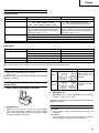
Variable speed
WH 12DAF2
•
WR 12DAF2
Cordless Impact Driver/Wrench
Akku-Schlagschrauber
¢Ú··ÓÔηÙÛ¿‚È‰Ô ª·Ù·Ú›·˜/∫ÏÂȉ›
Bezprzewodowa wkrętarka udarowa
Akkus ütvecsavarozó/Csavarkulcs
Rázový utahovák/Klíč
Akülü darbeli vidalama/anahtar
ìÀapÌêÈ aÍÍyÏyÎÓÚopÌêÈ åypÔoÇepÚ
Read through carefully and understand these instructions before use.
Diese Anleitung vor Benutzung des Werkzeugs sorgfältig durchlesen und verstehen.
¢È·‚¿ÛÙ ÚÔÛÂÎÙÈο Î·È Î·Ù·ÓÔ‹ÛÂÙ ·˘Ù¤˜ ÙȘ Ô‰ËÁ›Â˜ ÚÈÓ ÙË ¯Ú‹ÛË.
Przed użytkowaniem należy dokładnie przeczytać niniejszą instrukcję i zrozumieć jej treść.
Használat előtt olvassa el figyelmesen a használati utasítást.
Před použitím si pečlivě přečtěte tento návod a ujistěte se, že mu dobře rozumíte.
Aleti kullanmadan önce bu kılavuzu iyice okuyun ve talimatları anlayın.
BÌËÏaÚeÎëÌo ÔpoäÚËÚe ÀaÌÌyï ËÌcÚpyÍáËï Ôo íÍcÔÎyaÚaáËË ÔpeÊÀe äeÏ ÔoÎëÁoÇaÚëcÓ ËÌcÚpyÏeÌÚoÏ.
Handling instructions
Bedienungsanleitung
√‰ËÁ›Â˜ ¯ÂÈÚÈÛÌÔ‡
Instrukcja obsługi
Kezelési utasítás
Návod k obsluze
Kullanım talimatları
àÌcÚpyÍáËÓ Ôo íÍcÔÎyaÚaáËË
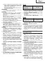
WH12DAF2
WR12DAF2

1
1
4
3
87
1
2
8
7
6
H
E
C
I
E
C
F
G
1
2
1
3
2
5
4
〈UC14YFA〉
9
A
0
1
8
7
6
6
C
D
E
〈UC18YG〉
B

2
14
O
J
N
13
3
M
J
11
K
J
12
L
109
(A)
5
1
J
16
,
.
,.
J
S
S
Q
R
T
R
15
Q
P
4
3
2
(B)

3
17
L
R
U
V V

4
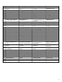
14.4 V Rechargeable
battery
Latch
Handle
Insert
Pull out
Insert
Pilot lamp
Hole for connecting the
rechargeable battery
Movement
Guide sleeve
Hexagonal hole in the
anvil
Driver bit
Hexagonal socket
Groove
Anvil
Pin
Ring
Hole
Plunger
Hook
Spring
Larger diameter faces
away
Switch
Phillips-head
screwdriver
Screw
Arrow
Hook cover
Indentation
Protuberance
AAAA batteries
Push button
Push
14,4 V aufladbare
Batterie
Verriegelung
Handgriff
Einsetzen
Herausziehen
Einsetzen
Kontrollampe
Anschlußloch für
Ladebatterir
Bewegung
Führungsmanschette
Sechskantloch in der
Schabotte
Dreherspitze
Sechskantbuchse
Nut
Schabotte
Stift
Ring
Öffnung
Preßkolben
Haken
Feder
Der große Durchmesser
weist zur anderen Seite
Schalter
Kreuzschlitzschrauben-
zieher
Schraube
Pfeil
Hakenabdeckung
Einkerbung
Vorsprung
Batterien der Größe
AAAA
Druckknopf
Drücken
English Deutsch ∂ÏÏËÓÈο Polski
1
2
3
4
5
6
7
8
9
0
A
B
C
D
E
F
G
H
I
J
K
L
M
N
O
P
Q
R
S
T
U
V
Akumulator 14,4 V
Zapadka
Rączka
Włóż/wprowadź
Wyciągnij
Włóż/wprowadź
Lampka kontrolna
Otwór wsuwowy
akumulatora
Ruch
Tuleja prowadnicy
Otwór sześciokątny w
kowadle
Wkrętak
Gniazdo sześciokątne
Rowek
Kowadło
Kołek
Pierścień
Otwór
Trzpień ruchomy
Hak
Sprężyna
Większa średnica jest
odwrócona
Przełącznik (włącznik/
wyłącznik)
Wkrętak Philipsa/
zgniazdkiem krzyżykowym
Śruba/wkręt
Strzałka
Pokrywa haka
Nacięcie
Wypukłość
Baterie AAAA
Przycisk
Wcisnąć
14,4V ∂·Ó·ÊÔÚÙÈ˙fiÌÂÓË
Ì·Ù·Ú›·
ª¿Ó‰·ÏÔ
ÃÂÚÔ‡ÏÈ
∂ÈÛ¯ˆÚ‹ÛÙÂ
∆Ú·‚‹ÍÙ ¤Íˆ
∂ÈÛ¯ˆÚ‹ÛÂÙÂ
¢ÔÎÈÌ·ÛÙÈ΋ Ï¿Ì·
∆Ú‡· ÁÈ· ÙËÓ Û‡Ó‰ÂÛË
Ù˘ ·ӷÊÔÚÙÈ˙fiÌÂÓ˘
Ì·Ù·Ú›·˜
∫›ÓËÛË
√‰ËÁËÙÈÎfi˜ ‚Ú·¯›ÔÓ·˜
∂Í¿ÁˆÓË ÙÚ‡· ÛÙÔÓ
¿ÎÌÔÓ·
§Â›‰· ΛÓËÛ˘
ª·ÎÚÈ¿ ˘Ô‰Ô¯‹
∞˘Ï¿ÎˆÛË
ÕÎÌÔÓ·˜
¶Â›ÚÔ˜
¢·ÎÙ‡ÏÈÔ˜
∆Ú‡·
ŒÌ‚ÔÏÔ
°¿ÓÙ˙Ô˜
∂Ï·Ù‹ÚÈÔ
∏ ÌÂÁ·Ï‡ÙÂÚË ‰È¿ÌÂÙÚÔ˜
‚ϤÂÈ ÚÔ˜ ¿ÏÏË
ηÙ‡ı˘ÓÛË
¢È·ÎfiÙ˘
∫·ÙÛ·‚›‰È ÎÂÊ·Ï‹˜
Phillips
µ›‰·
µ¤ÏÔ˜
∫¿Ï˘ÌÌ· ·ÁΛÛÙÚÔ˘
∞˘Ï¿ÎˆÛË
¶ÚÔÂÍÔ¯‹
∞∞∞∞ ̷ٷڛ˜
∫Ô˘Ì› ÒıËÛ˘
™ÚÒÍÂ

5
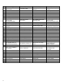
Magyar Čeština Türkçe PyccÍËÈ
1
2
3
4
5
6
7
8
9
0
A
B
C
D
E
F
G
H
I
J
K
L
M
N
O
P
Q
R
S
T
U
V
14,4 V-os tölthet
ő
akkumulátor
Retesz
Markolat
Bedugni
Kihúzni
Bedugni
Jelzőlámpa
Nyílás a tölthető
akkumulátor
csatlakoztatásához
Mozgás
Vezetőhüvely
Hatszögletű nyílás a
szárban
Behajtófej
Hatszögletű befogópatron
Vájat
Szár
Csap
Gyűrű
Nyílás
Hengeres csap
Kampó
Rúgó
A nagyobb átmérő az
ellenkező irány felé néz
Kapcsoló
Keresztfejes (Phillips-)
csavarhúzó
Csavar
Nyíl
A kampó fedele
Bemélyedés
Kidudorodás
AAAA méretű
szárazelemek
Nyomógomb
Benyomni
14,4V Akumulátor
Zámek
Držadlo
Zasunout
Zatáhnout
Zasunout
Indikátor
Otvor pro zasunutí
akumulátoru
Pohyb
Vodicí objímka
Šestihranný otvor v pevné
části
Hrot šroubováku
Šestihranný nástrčkový klíč
Drážka
Pevná část
Kolík
Kroužek
Otvor
Západkový čep
Páčka
Pružina
Větší průměr směřuje ven
Spínač
Křížový šroubovák
Šroub
Šipka
Kryt páčky
Prohlubeň
Výstupek
AAAA baterie
Tlačítko
Stisknout
14,4 V Íarj edilebilir
batarya
Mandal
Kol
Yerleßtirin
Çekin
Yerleßtirin
Kılavuz lamba
Íarj edilebilir bataryanın
takılacaåı delik
Hareket
Kılavuz segmanı
Örstekki altıgen delik
Tahrik ucu
Altıgen yuva
Yiv
Örs
Pim
Halka
Delik
Ótici
Askı
Yay
Büyük olan çap uzaåa
bakar
Íalter
Yıldız baßlı tornavida
Vida
Ok
Askı kapaåı
Girinti
Çıkıntı
AAAA piller
Kilit iånesi
Ótin
14,4 B aÍÍyÏyÎÓÚopÌaÓ
ÄaÚapeÓ
îËÍcaÚop
PyÍoÓÚÍa
BcÚaÇËÚë
BêÚaçËÚë
BcÚaÇËÚë
KoÌÚpoÎëÌaÓ ÎaÏÔa
OÚÇepcÚËe ÀÎÓ
ÔoÀÍÎïäeÌËÓ
aÍÍyÏyÎÓÚopÌoÈ ÄaÚapeË
èepeÏeçeÌËe
HaÔpaÇÎÓïçËÈ oÄoÀ
òecÚËÖpaÌÌoe
oÚÇepcÚËe Ç ÌaÍoÇaÎëÌe
HacaÀÍa åypyÔoÇepÚa
òecÚËÖpaÌÌoe ÖÌeÁÀo
KaÌaÇÍa
HaÍoÇaÎëÌÓ
òÚËÙÚ
KoÎëáo
OÚÇepcÚËe
èÎyÌÊep
KpïäoÍ
èpyÊËÌa
ÅoÎëåËÈ ÀËaÏeÚp
ÔoÇopaäËÇaeÚcÓ Ç
ÀpyÖyï cÚopoÌy
BêÍÎïäaÚeÎë
OÚÇepÚÍa c
ÍpecÚooÄpaÁÌoÈ
ÖoÎoÇÍoÈ
BËÌÚ
CÚpeÎÍa
KpêåÍa ÍpïäÍa
ìÖÎyÄÎeÌËe
BêcÚyÔ
AÍÍyÏyÎÓÚopÌêe
ÄaÚapeË AAAA
HaÊËÏÌaÓ ÍÌoÔÍa
HaÊaÚë

English
6
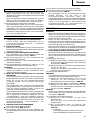
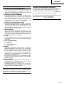
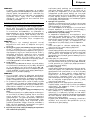
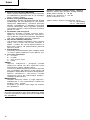
GENERAL OPERATIONAL PRECAUTIONS
WARNING! When using battery operated tools, basic
safety precautions should always be followed to reduce
the risk of fire, leaking batteries and personal injury,
including the following.
Read all these instructions before operating this product
and save these instructions.
For safe operations:
1. Keep work area clean. Cluttered areas and benches
invite injuries.
2. Consider work area environment. Do not expose
tools to rain. Do not use tools in damp or wet
locations. Keep work area well lit.
Do not use tools where there is risk to cause fire
or explosion.
3. Keep children away. Do not let visitors touch the
tool. All visitors should be kept away from work
area.
4. Store batteries or idle tools. When not in use,
tools and batteries should be stored separately in
a dry, high or locked up place, out of reach of
children.
Ensure that battery terminals cannot be shorted
by other metal parts such as screws nails etc.
5. Do not force the tool. It will do the job better and
safer at the rate for which it was intended.
6. Use the right tool. Do not force small tools or
attachments to do the job of a heavy duty tool.
Do not use tools for purposes not intended.
7. Dress properly. Do not wear loose clothing or
jewellery, they can be caught in moving parts.
Rubber gloves and non-skid footwear are
recommended when working outdoors. Wear
protecting hair covering to contain long hair.
8. Use safety glasses. Also use face or dust mask
if the cutting operation is dusty.
9. Connect dust extraction equipment.
If devices are provided for the connection of dust
extraction and collection facilities, ensure these
are connected and properly used.
10. Do not abuse the cord (if fitted). Never carry the
tool by the cord or yank it to disconnect it from
the socket. Keep the cord away from heat, oil and
sharp edges.
11. Secure work. Use clamps or a vice to hold the
work. It is safer than using your hand and it frees
both hands to operate the tool.
12. Do not overreach. Keep proper footing and balance
at all times.
13. Maintain tools with care. Keep cutting tools sharp
and clean for better and safer performance. Follow
instructions for lubrication and changing
accessories. Inspect tool cords periodically and if
damaged, have it repaired by authorized service
facility. Keep handles dry, clean, and free from oil
and grease.
14. Disconnect tools. Where the designs permits,
disconnect the tool from its battery pack, when
not in use, before servicing, and when changing
accessories such as blades, bits and cutters.
15. Remove adjusting keys and wrenches. Form the
habit of checking to see that keys and adjusting
wrenches are removed from the tool before turning
it on.
16. Avoid unintentional starting. Do not carry the tool
with a finger on the switch.
17. Stay alert. Watch what you are doing. Use common
sense. Do not operate the tool when you are tired.
18. Check damaged parts. Before further use of the
tool, a guard or other part that is damaged should
be carefully checked to determine that it will
operate properly and perform its intended function.
Check for alignment of moving parts, free running
of moving parts, breakage of parts, mounting and
any other conditions that may affect its operation.
A guard or other part that is damaged should be
properly repaired or replaced by an authorized
service center unless otherwise indicated in this
handling instructions. Have defective switches
replaced by an authorized service facility. Do not
use the tool if the switch does not turn it on and
off.
19. Warning
䡬 The use of any accessory or attachment, other
than those recommended in this handling instruc-
tions, may present a risk of personal injury.
䡬 Ensure that the battery pack is correct for the tool.
䡬 Ensure that the outside surface of battery pack or
tool is clean and dry before plugging into charger.
䡬 Ensure that batteries are charged using the correct
charger recommended by the manufacturer. In-
correct use may result in a risk of electric shock,
overheating or leakage of corrosive liquid from
the battery.
20. Have your tool repaired by a qualified person.
This tool is in accordance with the relevant safety
requirements. Repairs should only be carried out
by qualified persons using original spare parts,
otherwise this may result in considerable danger
to the user.
21. Disposal of battery
Ensure battery is disposed of safely as instructed
by the manufacturer.
22. If under abusive conditions, liquid is ejected from
the battery, avoid contact
If this accidentally occurs, frush with water. If
liquid contacts eyes additionally, seek medical
help.
PRECAUTIONS FOR CORDLESS IMPACT
DRIVER
1. This is portable tool for tightening and loosenig
screws. Use it only for these operation.
2. Use the earplugs if using for a long time.
3. One-hand operation is extremely dangerous; hold
the unit firmly with both hands when operating.
4. After installing the driver bit, pull lightly out the
bit to make sure that it does not come loose. If
the bit is not installed properly, it can come loose
during use, which can be dangerous.
5. Use the bit that matches the screw.
6. Tightening a screw with the impact driver at an
angle to that screw can damage the head of the
screw and the proper force will not be transmitted
to the screw. Tighten with this impact driver lined
up straight with the screw.
7. Always charge the battery at a temperature of 0
– 40°C.
A temperature of less than 0°C will result in over
charging which is dangerous. The battery cannot
be charged at a temperature greater than 40°C.
The most suitable temperature for charging is that
of 20 – 25°C.
8. Do not use the charger continuously.
When one charging is completed, leave the charger
for about 15 minutes before the next charging of
battery.
9. Do not allow foreign matter to enter the hole for
connecting the rechargeable battery.
10. Never disassemble the rechargeable battery and
charger.
11. Never short-circuit the rechargeable battery.
Short-circuiting the battery will cause a great
electric current and overheat. It results in burn or
damage to the battery.

English
7
12. Do not dispose of the battery in fire.
If the battery burnt, it may explode.
13. Do not insert object into the air ventilation slots
of the charger.
Inserting metal objects or inflammables into the
charger air ventilation slots will result in electrical
shock hazard or damaged charger.
14. Bring the battery to the shop from which it was
purchased as soon as the post-charging battery
life becomes too short for practical use. Do not
dispose of the exhausted battery.
15. Using an exhausted battery will damage the
charger.
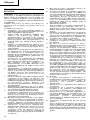
PRECAUTIONS FOR CORDLESS IMPACT
WRENCH
1. This is a portable tool for tightening and loosening
bolts and nuts. Use it only for these operation.
2. Use the earplugs if using for a long time.
3. One-hand operation is extremely dangerous; hold
the unit firmly with both hands when operating.
4. Check that the socket is not cracked or broken.
Broken or cracked sockets are dangerous. Check
the socket before using it.
5. Secure the socket with the socket pin and the ring.
If the socket pin or ring securing the socket is damaged,
the socket may come off from the impact wrench,
which is quite dangerous. Do not use socket pins
or rings that are deformed, worn out, cracked, or in
any other way damaged. Always make sure to install
the socket pin and ring in the correct position.
6. Check the tightening torque.
The appropriate torque for tightening a bolt
depends on the material the bolt is made of, its
dimensions, grade, etc.
Also, the tightening torque generated by this impact
wrench depends on the materials and dimensions
of the bolt, how long the impact wrench is applied
for the way in which the socket is installed, etc.
Also the torque when the battery has just been
charged and when it is about to run out are slightly
different. Use a torque wrench to check that the
bolt has been tightened with the appropriate torque.
7. Stop the impact wrench before switching the
direction of rotation. Always release the switch
and wait for impact wrench to stop before
switching the direction of rotation.
8. Never touch the turning part.
Do not allow the turning socket section to get near
your hands or any other part of your body. You could
be cut or caught in the socket. Also, be careful not
to touch the socket after using continuously it for
a long time. It gets quite hot and could burn you.
9. Never let the impact wrench turn without a load
when using the universal joint.
If the socket turns without being connected to a load,
the universal joint causes the socket to turn wildly.
You could get hurt or the movement of the socket
could shake the impact wrench so much as to
make you drop it.
10. Always charge the battery at a temperature of 0
– 40°C.
A temperature of less than 0°C will result in over
charging which is dangerous. The battery cannot
be charged at a temperature greater than 40°C.
The most suitable temperature for charging is
that of 20 – 25°C.
11. Do not use the charger continuously.
When one charging is completed, leave the charger
for about 15 minutes before the next charging of
battery.
12. Do not allow foreign matter to enter the hole for
connecting the rechargeable battery.
13. Never disassemble the rechargeable battery and
charger.
14. Never short-circuit the rechargeable battery.
Short-circuiting the battery will cause a great
electric current and overheat. It results in burn
or damage to the battery.
15. Do not dispose of the battery in fire.
If the battery burnt, it may explode.
16. Do not insert object into the air ventilation slots
of the charger.
Inserting metal objects or inflammables into the
charger air ventilation slots will result in electrical
shock hazard or damaged charger.
17. Bring the battery to the shop from which it was
purchased as soon as the post-charging battery
life becomes too short for practical use. Do not
dispose of the exhausted battery.
18. Using an exhausted battery will damage the
charger.
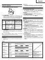
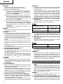
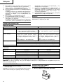
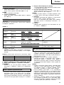
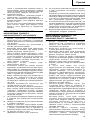
MODEL
WH12DAF2:with charger and case
WR12DAF2:with charger and case
SPECIFICATIONS
POWER TOOL
Model WH12DAF2 WR12DAF2
No-load speed 0 – 2500 min
–1
Capacity M4 – M8 (Small screw) M6 – M14 (Ordinary bolt)
M5 – M12 (Ordinary bolt) M6 – M10 (High tension bolt)
M5 – M10 (High tension bolt)
Tightening torque
Rechargeable battery EB1214S: Ni-Cd battery, 12 V (1.4 Ah 10 cells)
EB1220BL: Ni-Cd battery, 12 V (2.0 Ah 10 cells)
EB1226HL: Ni-MH battery, 12 V (2.6 Ah 10 cells)
Weight 1.6 kg (EB1214S Installation)
Maximum 130 N·m {1330 kgf·cm}
Tightening is M12 high tension bolt
(strength grade 12.9), when fully
charged at 20°C temp.
Tightening time: 3 sec.
Maximum 110 N·m {1120 kgf·cm}
Tightening is M12 high tension bolt
(strength grade 12.9), when fully
charged at 20°C temp.
Tightening time: 3 sec.

English
8
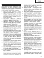
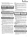
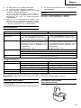
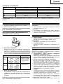
STANDARD ACCESSORIES
1. Charger (UC14YFA or UC18YG)............................... 1
2. Plastic case ................................................................ 1
Standard accessories are subject to change without
notice.
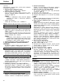
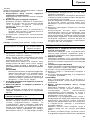
OPTIONAL ACCESSORIES
(Sold separately)
1. Battery (EB1214S, EB1220BL, EB1226HL)
2. For WH12DAF2
There are two types of attachment sizes for the driver
bit and the socket. Please refer to the table below and
select the attachment size for the driver bit or socket
that is appropriate for your WH12DAF2.
3. For WR12DAF2
The WR12DAF2 type is a 12.7 square driver
specification. Please select the socket with the
appropriate attachment size.
Optional accessories are subject to change without notice.
CHARGER
Model UC14YFA UC18YG
Charging time EB1214S: Approx. 30 min. (at 20°C) EB1214S: Approx. 30 min. (at 20°C)
EB1220BL: Approx. 50 min. (at 20°C) EB1220BL: Approx. 50 min. (at 20°C)
EB1226HL: Approx. 60 min. (at 20°C) ×
Charging voltage 7.2 – 14.4 V 7.2 – 18 V
Weight 0.6 kg 0.3 kg
“×” Indicates that the battery pack is not compatible with that specific charger.
NOTE: The charging time may vary according to the ambient temperature and power source voltage.
Attachment size Purchase location
Type-L
Type-S
Republic of Korea,
Taiwan, Hong Kong,
People’s Republic of
China, Republic of
Singapore
Other than above
regions.
17mm
12mm
13mm
9mm
APPLICATION
〈WH12DAF2〉
䡬 Driving and removing of small screws, small bolts,
etc.
〈WR12DAF2〉
䡬 Tightening and loosening of all types of bolts and
nuts, used for securing structural items
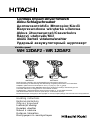
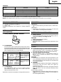
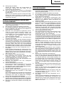
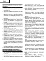
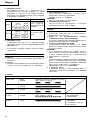
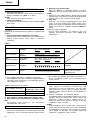
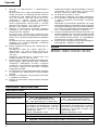
BATTERY REMOVAL/INSTALLATION
1. Battery removal
Hold the handle tightly and push the battery latch to
remove the battery. (See Fig. 1 and 2)
CAUTION:
Never short-circuit the battery.
2. Battery installation
Insert the battery while observing its polarities. (See
Fig. 2)
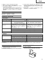
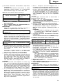
CHARGING
〈UC14YFA〉
Before using the power tool, charge the battery as follows.
1. Connect the charger’s power cord to a receptacle
When the power cord is connected, the charger’s
pilot lamp will blink in red. (At 1-second intervals.)
2. Insert the battery into the charger
Insert the battery firmly, in the direction shown in
Fig. 3, until it contacts the bottom of the charger
compartment.
CAUTION:
䡬 If the battery is inserted in the reverse direction, not
only recharging will become impossible, but it may
also cause problems in the charger such as deformed
recharging terminal.
3. Charging
When inserting a battery in the charger, charging will
commence and the pilot lamp will light up
continuously in red.
When the battery becomes fully recharged, the pilot
lamp will blink in red. (At 1-second intervals.) (See
Table 1)
(1) Pilot lamp indication
The indications of the pilot lamp will be as shown in
Table 1, according to the condition of the charger or
the rechargeable battery.

English
9
(2) Regarding the temperatures of the rechargeable battery
The temperatures for rechargeable batteries are as
shown in the table below, and batteries that have
become hot should be cooled for a while before
being recharged.
Table 2 Recharging ranges of batteries
4. Disconnect the charger’s power cord from the receptacle
5. Hold the charger firmly and pull out the battery
NOTE:
Be sure to pull out the battery from the charger after
use, and then keep it.
Regarding electric discharge in case of new
batteries, etc.
As the internal chemical substance of new batteries
and batteries that have not been used for an extended
period is not activated, the electric discharge might
be low when using them the first and second time.
This is a temporary phenomenon, and normal time
required for recharging will be restored by recharging
the batteries 2 – 3 times.
How to make the batteries perform longer
(1) Recharge the batteries before they become completely
exhausted.
When you feel that the power of the tool becomes
weaker, stop using the tool and recharge its battery.
If you continue to use the tool and exhaust the electric
current, the battery may be damaged and its life will
become shorter.
(2) Avoid recharging at high temperatures.
A rechargeable battery will be hot immediately after
use. If such a battery is recharged immediately after
use, its internal chemical substance will deteriorate,
and the battery life will be shortened. Leave the battery
and recharge it after it has cooled for a while.
CAUTION:
䡬 If the battery is charged while it is heated because it
has been left for a long time in a location subject to
direct sunlight or because the battery has just been
used, the pilot lamp of the charger lights up green. In
such a case, first let the battery cool, then start
charging.
䡬 When the pilot lamp flikers in red quickly (at 0.2-
second intervals), check for and take out any foreign
objects in the charger’s battery installation hole. If
there are no foreign objects, it is probable that the
battery or charger is malfunctioning. Take it to your
Authorized Service Center.
䡬 Since the built-in micro computer takes about 3
seconds to confirm that the battery being charged
with UC14YFA is taken out, wait for a minimum of 3
seconds before reinserting it to continue charging. If
the battery is reinserted within 3 seconds, the battery
may not be properly charged.
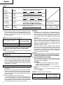
〈
UC18YG
〉
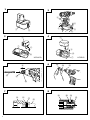
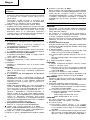
Before using the power tool, charge the battery as follows.
1. Connect the charger power cord to the receptacle
Connecting the power cord will turn on the charger.
2. Insert the battery into the charger
Insert the battery firmly while observing its direction,
until it contacts the bottom of the charger (the pilot
lamp lights up) (See Fig. 4).
CAUTION
If the pilot lamp does not light up, pull out the
power cord from the receptacle and check the
battery mounting condition.
䡬 Regarding the temperatures of the rechargeable
battery
The temperatures for rechargeable batteries are as
shown in Table 3.
Table 3 Recharging ranges of batteries
Temperatures at
Rechargeable batteries which the battery
can be recharged
EB1214S, EB1220BL –5°C – 60°C
EB1226HL 0°C – 45°C
Temperatures at
Rechargeable batteries which the battery
can be recharged
EB1214S, EB1220BL 0°C – 45°C
Lights for 0.5 seconds. Does not light for
0.5 seconds. (off for 0.5 seconds)
Lights continuously
Lights for 0.5 seconds. Does not light for
0.5 seconds. (off for 0.5 seconds)
Lights for 0.1 seconds. Does not light for
0.1 seconds. (off for 0.1 seconds)
Before
charging
While
charging
Charging
complete
Charging
impossible
Charging
impossible
Blinks
(RED)
Lights
(RED)
Blinks
(RED)
Flikers
(RED)
Lights
(GREEN)
Malfunction in the battery
or the charger.
The battery temperature
is high, making
recharging impossible.
Table 1
Indications of the lamps
Lights continuously

English
10
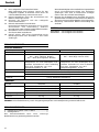
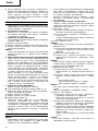
4. Selecting the socket matched to the bolt
(WR12DAF2)
Be sure to use a socket which is matched to the bolt
to be tightened. Using an improper socket will not
only result in insufficient tightening but also in
damage to the socket or nut.
A worn or deformed hex. or square-holed socket will
not give an adequate tightness for fitting to the nut or
anvil, consequently resulting in loss of tightening
torque.
Pay attention to wear of socket hole, and replace
before further wear has developed.
Finally, install the socket prescribed in Item 5. The
section on “Optional Accessories” details the
relationship between bolt sizes and sockets. Sockets
are named according to the dihedral width of the
hexagonal hole.
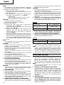
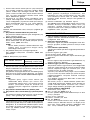
5. Installing a socket (WR12DAF2)
Select the socket to be used.
䢇 Pin, O-ring type (Fig. 6 and 7)
(1) Align the hole in the socket with the hole in the anvil
and insert the anvil into the socket.
(2) Insert the pin into the socket.
(3) Attach the ring to the groove on the socket.
䢇 Plunger type (Fig. 8)
Align the plunger located in the square part of the
anvil with the hole in the hex. socket. Then push the
plunger, and mount the hex. socket on the anvil.
Check that the plunger is fully engaged in the hole.
When removing the socket, reverse the sequence.
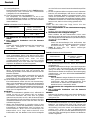
HOW TO USE
CAUTION:
䡬 When using the light equipped hook, pay sufficient
attention so that the main equipment does not fall. If
the tool falls, there is a risk of accident.
䡬 Do not attach the tip tool except phillips bit to the tool
main unit when carrying the tool main unit with the
light equipped hook suspended from a waist belt.
Injury may result if you carry the equipment
suspended from the waist belt with sharp tipped
components such as drill bit attached.
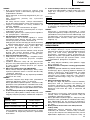
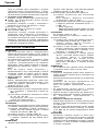
1. Using the light equipped hook
The light equipped hook can be installed on the right
or left side and the angle can be adjusted in 5 steps
between 0° and 80°.
(1) Operating the hook
(a) Pull out the hook toward you in the direction of
arrow (A) and turn in the direction of arrow (B).
(Fig. 9)
(b) The angle can be adjusted in 5 steps (0°, 20°, 40°,
60°, 80°).
Adjust the angle of the hook to the desired position
for use.
(2) Switching the hook position
CAUTION:
Incomplete installation of the hook may result in
bodily injury when used.
(a) Securely hold the main unit and remove the screw
using a slotted head screwdriver or a coin. (Fig.
10)
(b) Remove the hook and spring. (Fig. 11)
(c) Install the hook and spring on the other side and
securely fasten with screw. (Fig. 12)
䡬 The pilot lamp goes off to indicate that the battery is
fully charged.
The battery charging time becomes longer when a
temperature is low or the voltage of the power source
is too low.
When the pilot lamp does not go off even if more
than 120 minutes have elapsed after starting of the
charging, stop the charging and contact your HITACHI
AUTHORIZED SERVICE CENTER.
CAUTION
If the battery is heated due to direct sunlight, etc.,
just after operation, the charger pilot lamp may
not light up. At that time, cool the battery first,
then start charging.
3. Disconnect the charger’s power cord from the
receptacle
4. Hold the charger firmly and pull out the battery
NOTE
After charging, pull out batteries from the charger
first, and then keep the batteries properly.
Regarding electric discharge in case of new batteries,
etc.
As the internal chemical substance of new batteries
and batteries that have not been used for an extended
period is not activated, the electric discharge might
be low when using them the first and second time.
This is a temporary phenomenon, and normal time
required for recharging will be restored by recharging
the batteries 2 – 3 times.
How to make the batteries perform longer.
(1) Recharge the batteries before they become
completely exhausted.
When you feel that the power of the tool becomes
weaker, stop using the tool and recharge its battery.
If you continue to use the tool and exhaust the electric
current, the battery may be damaged and its life will
become shorter.
(2) Avoid recharging at high temperatures.
A rechargeable battery will be hot immediately after
use. If such a battery is recharged immediately after
use, its internal chemical substance will deteriorate,
and the battery life will be shortened. Leave the
battery and recharge it after it has cooled for a while.
PRIOR TO OPERATION
1. Preparing and checking the work environment
Make sure that the work site meets all the conditions
laid forth in the precautions.
2. Checking the battery
Make sure that the battery is installed firmly. If it is at
all loose it could come off and cause an accident.
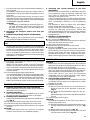
3. Installing the bit (WH12DAF2)
Always follow the following procedure to install driver
bit. (Fig. 5)
(1) Pull the guide sleeve away from front of the tool.
(2) Insert the bit into the hexagonal hole in the anvil.
(3) Release the guide sleeve and it returns to its original
position.
CAUTION:
If the guide sleeve does not return to its original
position, then the bit is not installed properly.

English
11
NOTE:
Pay attention to the spring orientation. Install the
spring with larger diameter away from you. (Fig. 12)
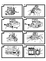
(3) Using as an auxiliary light
(a) Press the switch to turn off the light.
If forgotten, the light will turn off automatically
after 15 minutes.
(b) The direction of the light can be adjusted within
the range of hook positions 1 - 5. (Fig. 13)
䡬 Lighting time
AAAA manganese batteries: approx. 15 hrs.
AAAA alkali batteries: approx. 30 hrs.
CAUTION:
Do not look directly into the light.
Such actions could result in eye injury.
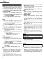
(4) Replacing the batteries
(a) Loosen the hook screw with a phillips-head
screwdriver (No. 1). (Fig. 14)
Remove the hook cover by pushing in the direction
of the arrow. (Fig. 15)
(b) Remove the old batteries and insert the new
batteries. Align with the hook indications and
position the plus (+) and minus (–) terminals
correctly. (Fig. 16)
(c) Align the indentation in the hook main body with
the protuberance of the hook cover, press the
hook cover in the direction opposite to that of the
arrow shown in Fig. 15 and then tighten the screw.
Use commercially available AAAA batteries
(1.5 V).
NOTE:
Do not tighten the screw excessively. Such action
could strip the screw threads.
CAUTION:
䡬 Failure to observe the following can result in battery
leakage, rust or malfunction.
Position the plus (+) and minus (–) terminals correctly.
Replace both batteries at the same time. Do not mix
old and new batteries.
Remove exhausted batteries from the hook
immediately.
䡬 Do not discard batteries together with normal trash
and do not throw batteries into fire.
䡬 Store batteries out of the reach of children.
䡬 Use batteries correctly in accordance with the battery
specifications and indications.
2. Check the rotational direction
The bit rotates clockwise (viewed from the rear side)
by pushing the R-side of the push button.
The L-side of the push button is pushed to turn the bit
counterclockwise. (See Fig. 17) (The
L
and
R
marks
are provided on the body.)
CAUTION:
The push button cannot be switched while the impact
driver is turning. To switch the push button, stop the
impact driver, then set the push button.
3. Switch operation
䡬 When the trigger switch is depressed, the tool rotates.
When the trigger is released, the tool stops.
䡬 The rotational speed can be controlled by varying the
amount that the trigger switch is pulled. Speed is low
when the trigger switch is pulled slightly and increases
as the trigger switch is pulled more.
4. Tightening and loosening screws (WH12DAF2)
Install the bit that matches the screw, line up the bit
in the grooves of the head of the screw, then tighten
it.
Push the impact driver just enough to keep the bit
fitting the head of the screw.
CAUTION:
Applying the impact driver for too long tightens the
screw too much and can break it.
Tightening a screw with the impact driver at an angle
to that screw can damage the head of the screw and
the proper force will not be transmitted to the screw.
Tighten with this impact driver lined up straight with
the screw.
5. Number of screws tightenings possible (WH12DAF2)
Please refer to the table below for the number of
screw tightened possible with one charge.
EB1214S
These values may vary slightly, according to
surrounding temperature and battery characteristics.
6. Number of bolt tightened possible (WR12DAF2)
Please refer to the table below for the number of bolt
tightened possible with one charge.
EB1214S
These values may vary slightly, according to
surrounding temperature and battery characteristics.
NOTE:
The use of the battery EB1226HL in a cold condition
(below 0 degree Centigrade) can sometimes result in
the weakened tightening torque and reduced amount
of work. This, however, is a temporary phenomenon,
and returns to normal when the battery warms up.
OPERATIONAL CAUTIONS
1. Resting the unit after continuous work
After use for continuous bolt-tightening work, rest
the unit for 15 minutes or so when replacing the
battery. The temperature of the motor, switch, etc.,
will rise if the work is started again immediately after
battery replacement, eventually resulting in burnout.
NOTE:
Do not touch the hammer case, as it gets very hot
during continuous work.
2. Cautions on use of the speed control switch
This switch has a built-in, electronic circuit which
steplessly varies the rotation speed. Consequently,
when the switch trigger is pulled only slightly (low
speed rotation) and the motor is stopped while
continuously driving in screws, the components of
the electronic circuit parts may overheat and be
damaged.
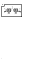
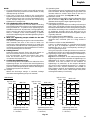
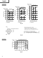
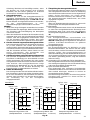
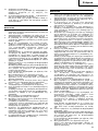
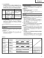
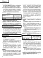
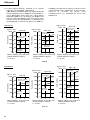
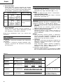
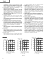
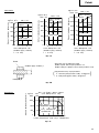
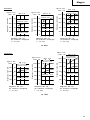
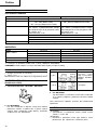
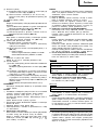
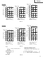
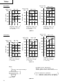
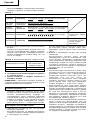
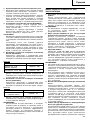
3. Tightening torque
Refer to Fig. 18 and Fig. 19 for the tightening torque
of bolts (according to size), under the conditions
shown in Fig. 20. Please use this example as a general
reference, as tightening torque will vary according to
tightening conditions.
Bolt used No. of tightenings
M12 × 45 High tension bolt
Approx. 87
Screw used No. of tightenings
Wood screw ø4 × 50
Approx. 190
(Soft wood)
Machine screw M8 × 16
Approx. 500

English
12
NOTE:
䡬 If a long striking time is used, screws will be strongly
tightened. This may cause the screw to break, or may
damage the tip of the bit.
䡬 If the unit is held at an angle to the screw being
tightened, the head of the screw may be damaged, or
the specified torque may not be transmitted to the
screw. Always keep the unit and the screw being
tightened in a straight line.
4. Use a tightening time suitable for the screw
The appropriate torque for a screw differs according
to the material and size of the screw, and the material
being screwed etc., so please use a tightening time
suitable for the screw. In particular, if a long tightening
time is used in the case of screws smaller than M8,
there is a danger of the screw breaking, so please
confirm the tightening time and the tightening torque
beforehand.
5. Work at a tightening torque suitable for the bolt
under impact
The optimum tightening torque for nuts or bolts differs
with material and size of the nuts or bolts. An
excessively large tightening torque for a small bolt
may stretch or break the bolt. The tightening torque
increases in proportion to the operaton time. Use the
correct operating time for the bolt.
6. Holding the tool
Hold the impact wrench firmly with both hands. In
this case hold the wrench in line with the bolt.
It is not necessary to push the wrench very hard.
Hold the wrench with a force just sufficient to
counteract the impact force.
7. Confirm the tightening torque
The following factors contribute to a reduction of the
tightening torque. So confirm the actual tightening
torque needed by screwing up some bolts before the
job with a hand torque wrench. Factors affecting the
tightening torque are as follows.
(1) Voltage
When the discharge margin is reached, voltage
decreases and tightening torque is lowered.
(2) Operating time
The tightening torque increases when the operating
time increases. But the tightening torque does not
increase above a certain value even if the tool is
driven for a long time. (See Fig. 18 and 19)
(3) Diameter of bolt
The tightening torque differs with the diameter of the
bolt as shown in Fig. 18 and 19. Generally a larger
diameter bolt requires larger tightening torque.
(4) Tightening conditions
The tightening torque differs according to the torque
ratio; class, and length of bolts even when bolts with
the same size threads are used. The tightening torque
also differs according to the condition of the surface
of workpiece through which the bolts are to be
tightened. When the bolt and nut turn together, torque
is greatly reduced.
(5) Using optional parts (WR12DAF2)
The tightening torque is reduced a little when an
extension bar, universal joint or a long socket is
used.
(6) Clearance of the socket (WR12DAF2)
A worn or deformed hex. or a square-holed socket
will not give an adequate tightness to the fitting
between the nut or anvil, consequently resulting in
loss of tightening torque.
Using an improper socket which does not match to
the bolt will result in an insufficient tightening torque.
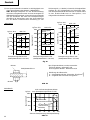
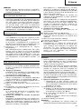
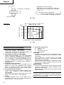
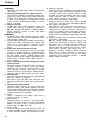
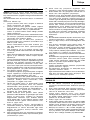
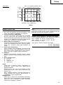
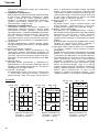
(7) Tightening torque varies, depending on the battery’s
charge level. (WR12DAF2)
Fig. 21 show examples of the relationship between
tightening torque and the number of tightenings, for
WR12DAF2. As shown, tightening torque gradually
weakens with the increase in the number of
tightenings. In particular, as the torque decreases
very close to the complete discharge (“a” margin in
graph), the unit’s impact weakens, the number of
time impacts declines and tightening torque drops
off abruptly. If this occurs, check torque level, then
recharge the battery if necessary.
Fig. 18
〈
WH12DAF2
〉
Tightening time: sec.
(Steel plate thickness
t = 10 mm)
High tension bolt
Ordinary bolt
M8 × 30
N
•
m
100
80
60
40
20
0
kgf
•
cm
1000
800
600
400
200
0
0123
Tightening time: sec.
(Steel plate thickness
t = 10 mm)
Ordinary bolt
High tension bolt
M10 × 30
N
•
m
100
80
60
40
20
0
kgf
•
cm
1000
800
600
400
200
0
0123
Tightening time: sec.
(Steel plate thickness
t = 25 mm)
Ordinary bolt
High tension bolt
M12 × 45
N
•
m
120
100
80
60
40
20
0
kgf
•
cm
1200
1000
800
600
400
200
0
0123
Tightening torque
Tightening torque
Tightening torque

English
13
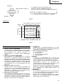
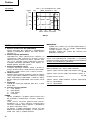
Nut
Fig. 20
Explanation of strength grade:
4 — Yield point of bolt: 32 kgf/mm
2
8 — Pulling strength of bolt: 40 kgf/mm
2
*The following bolt is used.
Ordinary bolt: Strength grade 4.8
High tension bolt: Strength grade 12.9
)(
Bolt
Steel plate thickness t
〈
WR12DAF2
〉
Fig. 19
Tightening torque
High tension
bolt
Tightening time: sec.
(Steel plate thickness
t = 10 mm)
Ordinary bolt
M8 × 30
N
•
m
100
80
60
40
20
0
kgf
•
cm
1000
800
600
400
200
0
0123
Tightening torque
Ordinary bolt
High tension
bolt
Tightening time: sec.
(Steel plate thickness
t = 10 mm)
M10 × 30
N
•
m
120
100
80
60
40
20
0
kgf
•
cm
1200
1000
800
600
400
200
0
0123
Ordinary bolt
Tightening torque
High tension
bolt
Tightening time: sec.
(Steel plate thickness
t = 25 mm)
M12 × 45
N
•
m
140
120
100
80
60
40
20
0
kgf
•
cm
1400
1200
1000
800
600
400
200
0
0123
Fig. 21
〈WR12DAF2〉
Tightening torque
M12 × 45 High tension bolt
(tighening time 3 sec)
When full recharged
When completely
discharged
Number of tightenings (PCS)/charging
N
•
m
160
120
80
40
0
kgf
•
cm
1600
1200
800
400
0
a
0 20 40 60 80 100

English
14
MAINTENANCE AND INSPECTION
1. Inspecting the driver bit (WH12DAF2)
Using a broken bit or one with a worn out tip is
dangerous because the bit can slip. Replace it.
2. Inspecting the socket (WR12DAF2)
A worn or deformed hex. or a square-holed socket
will not give an adequate tightness to the fitting
between the nut or anvil, consequently resulting in
loss of tightening torque. Pay attention to wear of a
socket holes periodically, and replace with a new one
if needed.
3. Inspecting the mounting screws
Regularly inspect all mounting screws and ensure
that they are properly tightened. Should any of the
screws be loose, retighten them immediately. Failure
to do so may result in serious hazard.
4. Cleaning of the outside
When the impact driver is stained, wipe with a soft
dry cloth or a cloth moistened with soapy water. Do
not use chloric solvents, gasoline or paint thinner, as
they melt plastics.
5. Storage
Store the impact driver in a place in which the
temperature is less than 40°C, and out of reach of
children.
6. Service parts list
A : Item No.
B : Code No.
C : No. Used
D : Remarks
CAUTION:
Repair, modification and inspection of Hitachi Power
Tools must be carried out by an Hitachi Authorized
Service Center.
This Parts List will be helpful if presented with the
tool to the Hitachi Authorized Service Center when
requesting repair or other maintenance.
In the operation and maintenance of power tools, the
safety regulations and standards prescribed in each
country must be observed.
MODIFICATIONS:
Hitachi Power Tools are constantly being improved
and modified to incorporate the latest technological
advancements.
Accordingly, some parts (i.e. code numbers and/or
design) may be changed without prior notice.
NOTE:
Due to HITACHI’s continuing program of reserch and
development, the specifications herein are subject to
change without prior notice.
Information concerning airborne noise and vibration
The measured values were determined according to
EN50260.
The typical A-weighted sound pressure level: 95 dB
The typical A-weighted sound power level: 108 dB
Wear ear protection.
The typical weighted root mean square acceleration
value: 9.6 m/s
2
(WH12DAF2)
7.6 m/s
2
(WR12DAF2)

Deutsch
15
ALLGEMEINE VORSICHTSMASSNAHMEN
WARNUNG! Bei der Arbeit mit akkubetriebenen
Werkzeugen sollten jederzeit grundlegende
Sicherheitsmaßnahmen befolgt werden, um die Gefahr
von Bränden, auslaufenden Akkus und Verletzungen zu
verringern. Dazu zählen die folgenden Dinge:
Lesen Sie diese Anweisungen völlig, bevor Sie dieses
Erzeugnis verwenden, und bewahren Sie diese
Anweisungen auf.
Für sicheren Betrieb:
1. Der Arbeitsplatz sollte sauber gehalten werden.
Unaufgeräumte Arbeitsplätze und Werkbänke
erhöhen die Unfallgefahr.
2. Wählen Sie eine vernünftige Arbeitsumgebung.
Setzen Sie Werkzeuge keinem Regen oder sonstigen
Flüssigkeiten aus. Verwenden Sie Werkzeuge nicht
an feuchten oder gar nassen Stellen. Sorgen Sie für
einen gut beleuchteten Arbeitsbereich.
Verwenden Sie Werkzeuge nicht an Orten, an denen
Brand- oder Explosionsgefahr besteht.
3. Halten Sie Kinder fern. Lassen Sie Werkzeuge nicht
von Zuschauern berühren. Sämtliche Zuschauer
sollten grundsätzlich vom Arbeitsbereich fern
gehalten werden.
4. Verstauen Sie Akkus und Werkzeuge, die nicht
gebraucht werden. Wenn Werkzeuge oder Akkus
nicht im Einsatz sind, sollten sie getrennt
voneinander an einem trockenen, hoch gelegenen
oder verschlossenen Ort außerhalb der Reichweite
von Kindern gelagert werden.
Achten Sie darauf, dass Akkukontake nicht durch
Metallgegenstände wie Schrauben, Nägel, und so
weiter kurzgeschlossen werden können.
5. Werkzeuge sollten nicht mit übermäßiger Gewalt
verwendet werden. Ihre Leistung ist besser und
sicherer, wenn sie mit der vorgeschriebenen
Geschwindigkeit verwendet werden.
6. Benutzen Sie immer das richtige Werkzeug.
Versuchen Sie nicht mit Gewalt, kleinere Werkzeuge
oder Zubehörteile für Arbeiten einzusetzen, für die
ein Hochleistungswerkzeug erforderlich ist.
Verwenden Sie Werkzeuge nicht für Dinge, für die
sie nicht gedacht sind.
7. Die richtige Kleidung tragen. Keine lose Kleidung
oder Schmuck tragen, da sich lose Kleidungsstücke
in den bewegenden Teilen verfangen können. Bei
Arbeiten im Freien sollten Gummihandschuhe und
rutschfeste Schuhe getragen werden. Tragen Sie
eine schützende Haarabdeckung, um langes Haar
zurückzuhalten.
8. Tragen Sie eine Schutzbrille. Benutzen Sie auch
eine Gesichts- oder Staubmaske, wenn Sie Arbeiten
ausführen, bei denen Staub anfällt.
9. Schließen Sie eine Staubabsaugvorrichtung an.
Wenn Vorrichtungen für den Anschluß von
Staubabsaug- und -sammelvorrichtungen
vorhanden sind, so stellen Sie sicher, daß diese
angeschlossen sind und richtig verwendet werden.
10. Gehen Sie sorgsam mit dem Anschlusskabel um
(sofern das Werkzeug mit einem solchen Kabel
ausgestattet ist ). Tragen Sie das Werkzeug niemals
am Kabel umher, ziehen Sie nicht am Kabel, wenn
Sie den Stecker aus der Steckdose ziehen möchten.
Halten Sie das Kabel von Hitze, Öl und scharfen
Kanten fern.
11. Den Arbeitsplatz gut absichern. Zwingen oder einen
Schraubstock zur Befestigung des Werkstücks
verwenden. Das ist sicherer als die Benutzung der
Hände und macht beide Hände zur Bedienung des
Werkzeugs frei.
12. Sich niemals weit überbeugen. Immer einen festen
Stand und ein sicheres Gleichgewicht bewahren.
13. Warten Sie Werkzeuge mit Sorgfalt. Halten Sie
Schneidwerkzeuge scharf und sauber; auf diese
Weise erbringen sie eine bessere und sicherere
Leistung. Halten Sie sich an Vorschriften hinsichtlich
Schmierung und Austausch von Zubehörteilen.
Inspizieren Sie die Kabelverbindungen des
Werkzeugs von Zeit zu Zeit. Falls diese beschädigt
sein sollten, lassen Sie diese von einer autorisierten
Fachkraft reparieren. Halten Sie Handgriffe trocken,
sauber und frei von Öl und sonstigen
Schmiermitteln.
14. Stromversorgung trennen
Wenn es die Bauart erlaubt, trennen Sie das
Werkzeug von seinem Akku, wenn es nicht im
Einsatz ist, vor Wartungsarbeiten und beim
Wechseln von Zubehörteilen wie Klingen, Bits und
Schneidwerkzeugen.
15. Alle Stellkeile und Schraubenschlüssel entfernen.
Vor Einschaltung des Gerätes darauf achten, daß
alle Stellkeile und Schraubenschlüssel entfernt
worden sind.
16. Vermeiden Sie unbeabsichtigten Anlauf des
Werkzeugs. Tragen Sie das Werkzeug nicht mit dem
Finger am Schalter herum.
17. Den Arbeitsvorgang immer unter Kontrolle haben.
Das Gerät niemals in einem abgespannten Zustand
verwenden.
18. Beschädigte Teile überprüfen. Vor Benutzung des
Werkzeugs sollten beschädigte Teile oder
Schutzvorrichtungen sorgfältig überprüft werden,
um festzustellen, ob sie einwandfrei funktionieren
und die vorgesehene Funktion erfüllen, Ausrichtung,
Verbindungen sowie Anbringung sich bewegender
Teile überprüfen. Ebenfalls uberprufen, ob Teile
gebrochen sind. Teile oder Schutzvorrichtungen,
die beschädigt sind, sollten, wenn in dieser
Bedienungsanleitung nichts anderes erwähnt ist,
durch eine autorisierte Kundendienststelle ausge
wechselt oder repariert werden. Lassen Sie defekte
Schalter von einer autorisierten Fachkraft reparieren.
Benutzen Sie das Werkzeug nicht, wenn es sich
nicht am Schalter ein- und ausschalten lässt.
19. Warnung
䡬 Die Verwendung von anderem Zubehör oder
anderen Zusätzen als in dieser
Bedienungsanleitung empfohlen kann das Risiko
einer Körperverletzung einschließen.
䡬 Vergewissern Sie sich, dass sich der Akku zum
Einsatz mit dem jeweiligen Werkzeug eignet.
䡬 Sorgen Sie dafür, dass die Außenseite von Akkus
und Werkzeugen gereinigt und trocken ist, bevor
Sie das Ladegerät anschließen.
䡬 Achten Sie darauf, dass Akkus mit dem richtigen,
vom Hersteller empfohlenen, Ladegerät aufgeladen
werden. Ein falscher Einsatz kann zu Brandgefahr,
Überhitzung oder zum Austreten ätzender
Flüssigkeiten aus dem Akku führen.
20. Lassen Sie Ihr Werkzeug von einer qualifizierten
Fachkraft reparieren.
Dieses Werkzeug erfüllt die zutreffenden
Sicherheitsbestimmungen. Reparaturen sollten
ausschließlich von qualifizierten Fachkräften unter
Verwendung von Original-Ersatzteilen ausgeführt
werden. Andernfalls kann es zu erheblichen
Gefährdungen des Benutzers kommen.

Deutsch
16
21. Entsorgung von Akkus
Achten Sie darauf, Akkus auf sichere Weise zu
entsorgen. Halten Sie sich dabei an die
Anweisungen des Herstellers.
22. Falls aus irgendwelchen Gründen eine Flüssigkeit
aus dem Akku austreten sollte, vermeiden Sie jeden
Kontakt damit.
Falls dies aus Versehen einmal vorkommen sollte,
spülen Sie sofort gründlich mit Wasser. Falls
Flüssigkeit in Ihre Augen geraten sollte, suchen Sie
sofort einen Arzt auf.
VORSICHTSMASSNAHMEN FÜR DEN AKKU-
SCHLAGSCHRAUBER
1. Dies ist ein tragbares Werkzeuggerät zum Anziehen
und Lösen von Schrauben. Es sollte nur für diesen
Zweck eingesetzt werden.
2. Bei längerem Arbeiten Ohrstöpsel verwenden.
3. Es ist äußerst gefährlich, das Gerät nur mit einer
Hand zu bedienen. Das Gerät ist beim Betrieb mit
beiden Händen festzuhalten.
4. Nachdem das Schraubstück angebracht wurde,
sollte ein wenig daran gezogen werden, um
sicherzugehen, daß es festsitzt. Wenn das
Schraubstück nicht richtig aufgesetzt wird, kann es
sich während des Betriebs lösen, was
Verletzungsgefahr bedeutet.
5 Das Schrubstück gemäß der anzuziehenden
Schraube verwenden.
6. Sollte versucht werden, mit dem Schlag-Schrauber
eine Schraube anzuziehen, wenn sich der Schlag-
Schrauber in einem Winkel zur Schraube befindet,
kann die Preßkraft des Geräts nicht voll zur Geltung
kommen; außer dem kann der Schraubenkopf
beschädigt werden. Anziehen, wenn sich der Schlag-
Schrauber mit der Schraube auf einer Linie befindet.
7. Die Batterie immer bei einer Temperatur von 0 –
40°C laden.
Laden bei einer Temperatur die niedriger als 0°C is
twird gefährliche Überladung verursachen. Die
Batterie kann nicht bei einer Temperatur über 40°C
geladen werden. Die beste Temperatur zum Laden
wäre von 20 – 25°C.
8. Das Ladegerät nicht fortlaufend laden.
Nach Beendung einer Ladung, lassen Sie das
Ladegerät ungefähr 15 Minuten ruhen bevor die
nächste Batterieladung unternommen wird.
9. Keine Fremdkörper durch das Anschlußloch der
Batterie eindringen lassen.
10. Niemals die Batterie und das Ladegerät
auseinandernehmen.
11. Niemals die Batterie kurzschließen.
Kurzschluß der Batterie verursacht eine zu große
Stromzufuhr und Überhitzung, wodurch
Durchbrennen oder Schaden beider Batterie ensteht.
12. Die Batterie nicht ins Feuer werfen.
Sie könnte dabei explodieren.
13. Darauf achten, daß keine Gegenstände durch
Belüftungsschlitze des Aufladers in das Gerät
eindringen.
Wenn Metallobjekte oder entzündliche Gegenstände
durch die Belüftungsschlitze des Aufladers
eindringen, kann dies zu elektrischen Schlägen
führen oder den Auflader beschädigen.
14. Bringen Sie die Batterie zum Geschäft, wo Sie ihn
gekauft haben sobald die Lebensdauer der Batterie
abrinnent. Die erschöpfte Batterie nicht wegwerfen.
15. Benutzung verbrauchter Batterie beschädigt den
Auflader.
VORSICHTSMASSNAHMEN FÜR DEN AKKU-
SCHLAGSCHRAUBER
1. Dies ist ein tragbares Werkzeuggerät zum Anziehen
und Lösen von Schrauben. Es sollte nur für diesen
Zweck eingesetzt werden.
2. Bei längerem Arbeiten Ohrstöpsel verwenden.
3. Es ist äußerst gefährlich, das Gerät nur mit einer
Hand zu bedienen. Das Gerät ist beim Betrieb mit
beiden Händen festzuhalten.
4. Nachprüfen, ob die Buchse gesprungen oder
gebrochen ist. Gebrochene und gesprungene
Buchsen sind gefährlich, daher die Buchse vor
Gebrauch prüfen.
5. Die Buchse mit Buchsenstift und-ring sichern. Sollte
der Buchsenstift oder-ring beschädigt sein, kann die
Buchse vom Schlag-Schraubenschlüssel
geschleudert werden, was gefährlich ist. Niemals
Buchsenstifte oder-ring verwenden, die deformiert,
abgenutzt, gesprungen oder sonstwie beschädigt
sind. Immer darauf achten, daß Buchsenstift und
-ring in der richtigen Position sind.
6. Das Anzugsdrehmoment prüfen.
Das geeignete Drehmoment für das Anziehen einer
Schraube hängt vom Material, der Art, den
Abmessungen, usw. der Schraube ab.
Außerdem hängt das von diesem Schlag-
Schraubenschlüssel erzeugte Auzugsdrehmoment
vom Material und den Abmessungen der Schraube,
für welche zeitdauer der Schlag-Schraubenschlüssel
angewendet wird, wie die Bushse angebracht ist,
usw. ab.
Das Drehmomentvariiert auch leicht, wenn die
Batterie gerade aufgeladen wurde und wenn sie
kurz vor dem Erschöpfen steht. Mit einem
Anzugsdrehmomentschlüssel nachprüfen, ob die
Schraube mit dem richtigen Drehmoment
angezogen wurde.
7. Den Schlag-Schraubenschlüssel zuerst stoppen,
wenn die Rotationsrichtung geändert werden soll.
Den Schalter immer erst freigeben und warten, bis
der Schlag-Schraubenschlüssel stoppt, bevor auf
die entgegengesetzte Rotationsrichtung geschaltet
wird.
8. Niemals die rotierenden Teile berühren.
Darauf achten, daß sich der rotierende Buchsenteil
immer in genügendem Abstand zum Körper und
den Händen befindet, da die Gefahr besteht, sich
zu schneiden oder sich in der Buchse zu verfangen.
Die Buchse sollte auch nicht direkt nach langer
kontinuierlicher Benutzuntg berührt werden, da
durch die erzeugte Hitze Verbrennungsgefhr
besteht.
9. Den Schlag-Schraubenschlüssel bei Benutzung des
Universalgelenks niemals ohne Einspannung
rotieren lassen.
Wenn sich die Buchse ohne eingespannt zu sein
dreht verusacht das Universalgelenk ein wildes
Rotieren der Buchse.
Durch die schnelle Rotation der Buchse kann der
Schlag-Schrauber so stark vibrieren, daß er
losgelassen werden muß.
10. Die Batterie immer bei einer Temperatur von 0 -
40°C laden.
Laden bei einer Temperatur die niedriger als 0°C is
twird gefährliche Überladung verursachen. Die
Batterie kann nicht bei einer Temperatur über 40°C
geladen werden. Die beste Temperatur zum Laden
wäre von 20 - 25°C.

Deutsch
17
11. Das Ladegerät nicht fortlaufend laden.
Nach Beendung einer Ladung, lassen Sie das
Ladegerät ungefähr 15 Minuten ruhen bevor die
nächste Batterieladung unternommen wird.
12. Keine Fremdkörper durch das Anschlußloch der
Batterie eindringen lassen.
13. Niemals die Batterie und das Ladegerät
auseinandernehmen.
14. Niemals die Batterie kurzschließen.
Kurzschluß der Batterie verursacht eine zu große
Stromzufuhr und Überhitzung, wodurch
Durchbrennen oder Schaden beider Batterie ensteht.
15. Die Batterie nicht ins Feuer werfen.
Sie könnte dabei explodieren.
16. Darauf achten, daß keine Gegenstände durch
Belüftungsschlitze des Aufladers in das Gerät
eindringen.
Wenn Metallobjekte oder entzündliche Gegenstände
durch die Belüftungsschlitze des Aufladers
eindringen, kann dies zu elektrischen Schlägen
führen oder den Auflader beschädigen.
17. Bringen Sie die Batterie zum Geschäft, wo Sie ihn
gekauft haben sobald die Lebensdauer der Batterie
abrinnent. Die erschöpfte Batterie nicht wegwerfen.
18. Benutzung verbrauchter Batterie beschädigt den
Auflader.
MODELL
WH12DAF2 : mit Ladegerät und Gehäuse
WR12DAF2 : mit Ladegerät und Gehäuse
STANDARDZUBEHÖR
ELEKTRO–WERKZEUG
Modell WH12DAF2 WR12DAF2
Leerlaufdrehzahl 0 – 2500 min
–1
Kapazität M4 – M8 (Kleine Schraube) M6 – M14 (Ordinary bolt)
M5 – M12 (Üblicher Bolzen) M6 – M10 (High tension bolt)
M5 – M10 (Hochzugfester Bolzen)
Spanndrehkraft
Wiederaufladbare EB1214S: Ni-Cd Batterie, 12 V (1,4 Ah 10 Zellen)
Batterie EB1220BL: Ni-Cd Batterie, 12 V (2,0 Ah 10 Zellen)
EB1226HL: Ni-MH Batterie, 12 V (2,6 Ah 10 Zellen)
Gewicht 1,6 kg (EB1214S–Installation)
Maximum 110 N·m
{1120 kgf·cm}
Festspannen von M12 (Härtegrad 12,9)
reißfeste Schraube bei voller Aufladung
und einer Temperatur von 20°C.
Festspannungsdauer: 3 Sek.
Maximum
130 N·m {1330 kgf·cm}
Festspannen von M12 (Härtegrad 12,9)
reißfeste Schraube bei voller Aufladung
und einer Temperatur von 20°C.
Festspannungsdauer: 3 Sek.
LADEGERÄT
Modell UC14YFA UC18YG
Ladedauer EB1214S: Etwa. 30 min. (bei 20°C) EB1214S: Etwa. 30 min. (bei 20°C)
EB1220BL: Etwa. 50 min. (bei 20°C) EB1220BL: Etwa. 50 min. (bei 20°C)
EB1226HL: Etwa. 60 min. (bei 20°C) ×
Ladespannung 7,2 – 14,4 V 7,2 – 18 V
Gewicht 0,6 kg 0,3 kg
„ד bedeutet, dass die Akkus zu diesem bestimmten Ladegerät nicht kompatibel sind.
HINWEIS: Die Aufladezeit kann je nach Umgebungstemperatur und Ladespannung unterschiedlich sein.
STANDARDZUBEHÖR
1. Ladegerät (UC14YFA oder UC18YG) ....................... 1
2. Plastikgehäuse .......................................................... 1
Das Standardzubehör kann ohne vorherige
Bekanntmachung jederzeit geändert werden.

Deutsch
18
SONDERZUBEHÖR
(separat zu beziehen)
1. Batterie (EB1214S, EB1220BL, EB1226HL)
2. Für WH12DAF2
Es gibt zwei Buchsengrößen für Dreherspitze und
Kupplung. Bitte schauen Sie in die nachstehende
Tabelle und wählen Sie die passende Kupplungsgröße
für Dreherspitze und Kupplung Ihres WH12DAF2.
3. Für WR12DAF2
Die WR12DAF2 arbeitet mit einem 12,7-Vierkantkopf.
Bitte wählen Sie die Buchse in der passenden
Kupplungsgröße.
Das Sonderzubehör kann ohne vorherige
Bekanntmachung jederzeit geändert werden.
ANWENDUNG
〈WH12DAF2〉
䡬 Drehen und Lösen vom Kleinen Schrauben, Kleiner
Bolzen, usw.
Leuchtet für 0,5 Sekunden.
Erlischt für 0,5 Sekunden. (aus für 0,5 Sekunden)
Leuchtet kontinuierlich
Leuchtet für 0,5 Sekunden.
Erlischt für 0,5 Sekunden. (aus für 0,5 Sekunden)
Leuchtet für 0,1 Sekunden.
Erlischt für 0,1 Sekunden. (aus für 0,1 Sekunden)
Leuchtet kontinuierlich (aus für 0,1 Sekunden)
Vor dem
Laden
Beim Laden
Laden
durchgeführt
Laden
unmöglich
Laden
unmöglich
Blinkt
(ROT)
Leuchtet
(ROT)
Blinkt
(ROT)
Flackert
(ROT)
Leuchtet
(GRÜN)
Betriebsstörung in der
batterie oder im
Ladegerät.
Die Temperatur der
Batterie ist hoch,
wodurch das Aufladen
unmöglich wird.
Tafel 1
Anzeigen der Kontrollampe
〈WR12DAF2〉
䡬 Festspannen aller Arten von Bolzen und Muttern,
verwendet zum Befestigen von Konstruktionsteilen.
HERAUSNEHMEN/EINSETZEN DER BATTERIE
1. Herausnehmen der Batterie
Den Handgriff fest halten und die Akkumulator-
Verriegelung drücken, um den Akkumulator
herauszunehmen. (Siehe Abb. 1 und 2)
ACHTUNG:
Die Kontakte des Batterie niemals kurzschließen.
2. Einsetzen des Batterie
Den Batterie unter Beachtung der richtigen Richtung
in das Gerät einsetzen. (Siehe Abb. 2)
LADEN
〈UC14YFA〉
Laden Sie den Akku wie folgt, bevor Sie das
Motorwerkzeug verwenden.
1. Den Netzstecker des Ladegerätes in eine Steckdose
einstecken
Beim Anschluß des Ladegeräts an eine Netzsteckdose
blinkt die Kontrollampe in Rot auf. (In
Sekundenabständen.)
2. Eine Batterie in das Ladegerät einlegen
Schieben Sie den Akku bestimmt in der in Abb. 3
gezeigten Richtung ein, bis er in Kontakt mit dem
Boden des Ladegerätfachs kommt.
ACHTUNG:
䡬 Wenn die Batterie verkehrt herum eingelegt wird,
kann nicht nur die Batterie nicht geladen werden,
sondern es kann auch zu Verformung der
Ladeklemmen oder anderen Störungen im Ladegerät
kommen.
3. Anzeigelämpchen
Beim Einlegen einer Batterie in das Ladegerät wird
der Ladevorgang fortgesetzt, und leuchtet die
Kontrollampe kontinuierlich in Rot auf.
Wenn die Batterie voll aufgelader ist, blinkt die
Kontrollampe in Rot. (in Sekundenabständen). (Seihe
Tafel 1)
17mm
12mm
13mm
9mm
Kupplungsgröße Ort des Erwerbs
Typ-L
Typ-S
Republik Korea,
Taiwan, Hongkong,
Volksrepublik China,
Republik Singapur
Sonstige Region.

Deutsch
19
vor. Die Teile vom autorisierten Kundendienst prüfen
lassen.
䡬 Da der eingebaute Mikrocomputer etwa 3 Sekunden
braucht, um zu bestätigen, daß die im UC14YFA zum
Laden eingelegte Batterie herausgenimmen wird,
warten Sie mindestens 3 Sekunden, bevor Sie die
Batterie zum Fortsetzen des Aufladens einlegen. Wenn
die Batterie innerhalb von 3 Sekunden eingelegt wird,
kann es sein, daß sie nicht richtig geladen wird.
〈UC18YG〉
Laden Sie den Akku wie folgt, bevor Sie das
Motorwerkzeug verwenden.
1. Das Ladegerätkabel an den Wechselstromausgang
schließen
Dadurch wird das Ladegerät eingeschaltet.
2. Die Batterie in das Ladegerät einlegen
Bitte schieben Sie den Akkumulator sicher unter
Beachtung seiner Richtung ein, bis er mit dem Boden
des Ladegerätes Kontakt bekommt (die Kontrollampe
leuchtel auf) (Siehe Abb. 4).
VORSICHT
Wenn die Kontrollampe nicht aufleuchtet, das
Netzkabel von der Steckdose abtrennen und die
Einsetzrichtung der Batterie prüfen.
䡬 Tafel 3 zeigt den für Akkus zulässigen
Temperaturbereich.
Tafel 3 Aufladebereiche für Batterien
䡬 Die Kontrollampe erlischt, wenn die Batterie
vollgeladen ist.
Die Batterieladezeit wird länger, wenn die Temperatur
zu niedrig oder die Spannung der Stromquelle zu
gering ist. Wenn das Anzeigelämpchen auch nach
120 Minuten Aufladen nicht erlischt, den Ladevorgang
unterbrechen, und den HITACHI-KUNDENDIENST
benachrichtigen.
VORSICHT
Falls die Batterie wegen direkten Sonnenstrahlen,
usw., gleich nach Betrieb überhitzt wird, mag es
vorkommen, daß die Ladekontrollampe nicht
aufleuchtet. In diesem Fall, die Batterie zuerst
abkühlen lassen, und danach laden.
3. Den Netzstecker des Ladegeräts aus der Steckdose
ziehen
4. Das Ladegerät festhalten und die Batterie
herausziehen
HINWEIS
Nehmen Sie die Akkus gleich nach dem Aufladen aus
dem Ladegerät und lagern Sie sie an einem
geeigneten Ort.
Zur Leistung von neuen Batterien.
Da die Batteriechemikalien von neuen Batterien und
Batterien, die längere Zeit über nicht verwen det
wurden, noch nicht bzw. nicht mehr aktiv sind, kann
die Leistung von beim ersten und zweiten Einsatz
niedrig sein. Dies ist eine vorübergehende
Erscheinung, und die normale Batterieleistung wird
nach zwei-oder dreimaligem Aufladen der Batterien
wieder hergestellt.
Temperaturen, bei
Akkubatterien denen die Batterie
geladen werden kann
EB1214S, EB1220BL –5°C – 60°C
EB1226HL 0°C – 45°C
(1) Anzeigelämpchen
Die Kontrollampe leuchtet auf, wie in Tafel 1 gezeigt,
entsprechend dem Zustand des verwendeten
Ladegeräts für die Akkubatterie.
(2) Über die Temperatur der Akkubatterie
Die Temperatur von Akkubatterien ist wie in der
folgenden Abbildung gezeigt, und Batterien, die sich
zu stark erhitzt haben, sollten sich vor dem Aufladen
etwas abkühlen.
Tafel 2 Aufladebereiche für Batterien
4. Den Netzstecker des Ladegeräts aus der Steckdose
ziehen
5. Das Ladegerät festhalten und die Batterie
herausziehen
HINWEIS:
Achten Sie darauf, die Batterie nach der Verwendung
aus dem Ladegerät zu nehmen und sie
aufzubewahren.
Zur Leistung von neuen Batterien
Da die Chemikalien in neuen bzw. in längere Zeit
nicht verwendeten Akkus nicht aktiviert sind, kann
die elektrische Entladung bei der ersten und zweiten
Verwendung gering sein. Dies ist eine
vorübergehende Erscheinung, und die normale
Batterieleistung wird nach zwei-oder dreimaligem
Aufladen der Batterien wieder hergestellt.
Verlängerung der Lebensdauer von Batterien
(1) Die Batterien aufladen, bevor sie völlig erschöpft sind.
Wenn festgestellt wird, daß die Leistung des
Werkzeugs nachläßt, mit der Arbeit aufhören und die
Batterie aufladen.
Wenn das Werkzeug weiter verwendet wird und die
Batterie völlig erschöpft wird, kann die Batterie
beschädigt und ihre Lebensdauer verkürzt werden.
(2) Nicht bei hohen Temperaturen aufladen.
Eine Akkubatterie erhitzt sich bei der Verwendung.
Wenn solch eine Batterie sofort nach der Verwendung
aufgeladen wird, werden die Batteriechemikalien
beeinträchtigt, und die Batterielebensdauernimmt ab.
Die Batterie etwas stehen lassen und erst aufladen,
wenn sie sich abgekühlt hat.
ACHTUNG:
䡬 Wenn die Akkubatterie geladen wird, während sie
erhitzt ist weil sie sich längere Zeit im direkten
Sonnenlicht befunden hat, oder weil sie gerade
gebraucht wurde, kann es sein, daß die Kontrollampe
des Ladegeräts in Grün leuchtet. In diesem Fall zuerst
die Batterie abkühlen lassen und erst dann mit dem
Aufladen beginnen.
䡬 Wenn das Kontrollampe in schneller Folge in Rot
flackert (in 0,2-Sekun-den-Abständen), nachsehen ob
Fremdkörper im Batteriefach sind und diese ggf.
herausnehmen. Wenn keine Fremdkörper im
Batteriefach sind, liegt wahr-scheinlich eine
Fehlfunktion bei der Batterie oder beim Ladegerät
Temperaturen, bei denen
Akkubatterien die Batterie geladen
werden kann
EB1214S, EB1220BL 0°C – 45°C
Strona się ładuje...
Strona się ładuje...
Strona się ładuje...
Strona się ładuje...
Strona się ładuje...
Strona się ładuje...
Strona się ładuje...
Strona się ładuje...
Strona się ładuje...
Strona się ładuje...
Strona się ładuje...
Strona się ładuje...
Strona się ładuje...
Strona się ładuje...
Strona się ładuje...
Strona się ładuje...
Strona się ładuje...
Strona się ładuje...
Strona się ładuje...
Strona się ładuje...
Strona się ładuje...
Strona się ładuje...
Strona się ładuje...
Strona się ładuje...
Strona się ładuje...
Strona się ładuje...
Strona się ładuje...
Strona się ładuje...
Strona się ładuje...
Strona się ładuje...
Strona się ładuje...
Strona się ładuje...
Strona się ładuje...
Strona się ładuje...
Strona się ładuje...
Strona się ładuje...
Strona się ładuje...
Strona się ładuje...
Strona się ładuje...
Strona się ładuje...
Strona się ładuje...
Strona się ładuje...
Strona się ładuje...
Strona się ładuje...
Strona się ładuje...
Strona się ładuje...
Strona się ładuje...
Strona się ładuje...
Strona się ładuje...
Strona się ładuje...
Strona się ładuje...
Strona się ładuje...
Strona się ładuje...
Strona się ładuje...
Strona się ładuje...
Strona się ładuje...
Strona się ładuje...
Strona się ładuje...
Strona się ładuje...
Strona się ładuje...
Strona się ładuje...
Strona się ładuje...
Strona się ładuje...
Strona się ładuje...
Strona się ładuje...
Strona się ładuje...
Strona się ładuje...
Strona się ładuje...
Strona się ładuje...
Strona się ładuje...
Strona się ładuje...
Strona się ładuje...
Strona się ładuje...
Strona się ładuje...
-
 1
1
-
 2
2
-
 3
3
-
 4
4
-
 5
5
-
 6
6
-
 7
7
-
 8
8
-
 9
9
-
 10
10
-
 11
11
-
 12
12
-
 13
13
-
 14
14
-
 15
15
-
 16
16
-
 17
17
-
 18
18
-
 19
19
-
 20
20
-
 21
21
-
 22
22
-
 23
23
-
 24
24
-
 25
25
-
 26
26
-
 27
27
-
 28
28
-
 29
29
-
 30
30
-
 31
31
-
 32
32
-
 33
33
-
 34
34
-
 35
35
-
 36
36
-
 37
37
-
 38
38
-
 39
39
-
 40
40
-
 41
41
-
 42
42
-
 43
43
-
 44
44
-
 45
45
-
 46
46
-
 47
47
-
 48
48
-
 49
49
-
 50
50
-
 51
51
-
 52
52
-
 53
53
-
 54
54
-
 55
55
-
 56
56
-
 57
57
-
 58
58
-
 59
59
-
 60
60
-
 61
61
-
 62
62
-
 63
63
-
 64
64
-
 65
65
-
 66
66
-
 67
67
-
 68
68
-
 69
69
-
 70
70
-
 71
71
-
 72
72
-
 73
73
-
 74
74
-
 75
75
-
 76
76
-
 77
77
-
 78
78
-
 79
79
-
 80
80
-
 81
81
-
 82
82
-
 83
83
-
 84
84
-
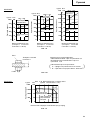 85
85
-
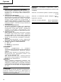 86
86
-
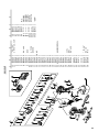 87
87
-
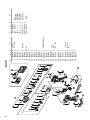 88
88
-
 89
89
-
 90
90
-
 91
91
-
 92
92
-
 93
93
-
 94
94


Hikoki WH 12DAF2 Instrukcja obsługi
- Kategoria
- Wkrętaki mocy
- Typ
- Instrukcja obsługi
w innych językach
- čeština: Hikoki WH 12DAF2 Uživatelský manuál
- Deutsch: Hikoki WH 12DAF2 Benutzerhandbuch
- português: Hikoki WH 12DAF2 Manual do usuário
- Türkçe: Hikoki WH 12DAF2 Kullanım kılavuzu
- English: Hikoki WH 12DAF2 User manual
Powiązane artykuły
Inne dokumenty
-
Hitachi WH 18DL Handling Instructions Manual
-
-
Bahco BCL31IW1K1 Instrukcja obsługi
-
-
-
Hitachi ds 9dvf3 Handling Instructions Manual
-
Tryton TJKU30 Instrukcja obsługi
-
-