
Page 1 of 4
Part Number Description Quantity
30920 Lock Washer, 1/4 inch 3
55142 Separator Drain Hose Assembly w/ Elbow 1
55981 Exhaust Hose Assembly w/ Teflon Tape 1
55499 VS80H Eductor Assembly 1
55498 VS50H Eductor Assembly 1
55147 1/2 inch OD Poly flow tubing, 14 inch Long 1
55231 1/4 inch OD Poly flow tubing, 18 inch Long 1
30914 Hex Head Bolt; 1/4-20x1/2 inch 3
30711 Hex Washer Head Screw; 10-24x1/2 inch 2
56057 Vent Hose and w/ Cuffs 1
49833 Hose Clamp, 2.5 to 3.5 inch diameter 2
56006 VS80 HydroMiser Assembly w/ Bracket & Water System 1
57278 1 inch Rubber Coupling (incl. w/ Separator Assembly) 1
56005 VS50 HydroMiser Assembly w/ Bracket & Water System 1
55927 Adapter Fitting,1 inch MNPTx1 inch Barb 1
HydroMiser Installation Kit
Part Numbers:
56041 for VacStar 50 (VS50)
56042 for VacStar 80 (VS80)
Installation Instructions
DENTAL VACUUM SYSTEMS
Supplied Components. This kit includes the following items listed below.
Tools Required. Tools needed but not supplied for this installation include the following.
7/16 inch Wrench 5/16 inch Nut Driver Phillips Screwdriver
Cutter Tape Measure Adjustable Pliers
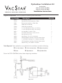
Review the FLOW DIAGRAM, below, before beginning installation.

Page 2 of 4
Prepare the VacStar to receive the hydromiser assembly
Note: 36 inch height clearance is required for proper vent installation.
A. Disconnect the power and shutoff the water supply
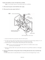
B. Disconnect the water system (See Fig. 1).
1. Disconnect both 3/8 inch poly flow tubes at the water system.
2. The other end of the 3/8 inch poly flow tubes are connected to the pump housing. Measure 13-1/2
inch from the tube fittings on the pump housing. Cut off the excess tubing.
3. Disconnect both 1/4 inch poly flow tubes at the bottom of the water system.
Note: Since one tube is longer than the other, make sure to install the tubes in same
place they were disconnected.
4. Remove and discard both water systems from the back rail using a Phillips screwdriver to disengage
the clamp.
C. Removeanddiscardtheexistingexhausthoseandttingbetweentheexhaustmanifoldand
the drain.
Cut off the exhaust hose. Use adjustable pliers to unscrew the rest of the fitting(See Figs.1 and 6).

Page 3 of 4
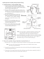
A. Installtheeductor;connectpolyowtubing.
1. Using a 5/16 inch nut driver and 2 hex washer head
screws provided, attach the eductor assembly’s bracket
to the base plate of the VacStar chassis. Set the eductor
valve on recycle mode (See Fig. 3).
2. Route the 3/8 inch poly flow tube from the left pump
assembly over the intake manifold to the left port of the
“Y” connector on the eductor assembly. Insert until the
tube stops (See Fig. 3).
C. ConnectthepolyowtubingtoHydroMiserAssembly(SeeFig.5).
1. Reconnect the 1/4 inch poly flow tubes between the bottom of the water system and the solenoids.
Note: Since one tube is longer than the other, make sure to install the tubes in same
place they were disconnected.
2. Insert the free end of the1/2 inch poly flow tube into the swivel fitting of the HydroMiser assembly
until the tube stops.(See Fig. 2).
3. Connect the1/4 inch poly flow tube from the tee fitting on top of the eductor assembly, (See Fig. 3),
to the elbow found at the top of the water system (See Fig. 2).
Install Hydromiser Assembly, Eductor, Reattach Tubing
3. Route the 3/8 inch poly flow tube from the
right pump assembly to the right port of the
“Y” connector on the eductor assembly.
Loop tubes to avoid kinks. Insert until the
tube stops.
4. Insert the 1/2 inch poly flow tube (incl. w/
kit) into the side port of the eductor assembly
until the tube stops (See Fig. 3).
5. Insert 1/4 inch poly flow tube (incl. w/kit)
into tee fitting on top of eductor assembly
until the tube stops (See Fig. 3).
Note: If, for any reason, it becomes necessary to remove a poly
flow tube held in place with a push to connect fitting,
simply push the outer ring in and pull on the tube.
B. Attach the HydroMiser assembly to the back rail of the VacStar.
Secure with 3 bolt and lock washer pairs (incl. w/kit). Tighten in
three places using a 7/16 inch wrench (See Fig. 4).

Page 4 of 4
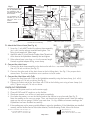
E. Connect the drain hose
1. Connect the drain hose assembly to the drain outlet with the 1 inch black rubber coupling.
Use a 5/16 inch nut driver (See Fig. 2).
2. Connect the other end of the drain hose to the building drain. See Fig. 5 for proper drain
connections. The drain installation must conform to local codes.
F. Connect the Vent Hose with Cuffs
1. Connect the Vent Hose with Cuffs to the HydroMiser assembly using the hose clamp, (incl. w/kit).
Tighten using a 5/16 inch nut driver (See Fig. 4).
2. Connect the other end of the Vent Hose with Cuffs to the building vent using a hose clamp (incl.
w/kit). Tighten using a 5/16 inch nut driver.
CHECK OUT PROCEDURE
1 Reconnect the power and turn on the water supply.
2. Close all HVE’s and SE’s and turn on the VacStar.
3. If leaks are present, turn off the unit and repair accordingly.
4. If no leaks are present, turn on the VacStar and set the eductor to recycle mode (See Fig. 3).
Note the reading on the vacuum gauge. Then, set the eductor to bypass mode. Note the reading
again on the vacuum gauge. If there is no more than 1 In Hg. difference between readings, the
HydroMiser has been installed successfully.
5. If the readings are not the same or widely different, review the installation. If the HydroMiser was installed
correctly, see the VacStar Service Technicians Manual, Trouble Shooting Guide, Low or No Suction.
D. Attach the Exhaust hose (See Fig. 6).
1. Screw the 1 inch MNPT end of the exhaust hose assembly
(incl. w/kit) into the exhaust manifold and tighten. This
fitting is pre-taped with Teflon tape.
2. Attach the other 3/4 inch Female Garden Hose Thread end
of the hose to the HydroMiser Assembly inlet and tighten.
3. If the exhaust hose is too long, cut it to the correct length
& attach supplied adapter fitting, reuse clamp.
VacStar is a trademark of Air Techniques, Inc.
© Copyright 2004 Air Techniques, inc.
PN 55377, Rev. D - November 2017
Air Techniques, Inc.
1295 Walt Whitman Road
Melville, New York, USA 11747- 3062
If the existing drain is higher
than the HydroMiser outlet,
the HydroMiser must be
mounted so that its outlet is
above the drain.
The HydroMiser can be
installed up to 32 inches
above the base of the
VacStar.
Order Kit PN 55087.
32 Inches
Maximum.
Power
Connection
HydroMiser
Eductor
(in back)
Intake from Main Line
Terminate with 1 inch FNPT fitting
Water Suppy 1/2”
copper tube termi-
nate with 1/2” FNPT
shut-off valve
WARNING:
Slope piping toward separator
to avoid accumulation of water
from condensation in vent.
Vent
Vent to outside with
2” schedule 40 pipe
Floor Sink
Note: See Optional Drain
Connections Bottom water system ¼ inch poly flow tubes
Exhaust
Hose
Vent Hose
with Cuffs
Fig. 5
¼ poly flow tube
Drain
Hose
½ poly flow tube
Swivel Fitting
-
 1
1
-
 2
2
-
 3
3
-
 4
4


Air Techniques Air/Water Separator Instrukcja obsługi
- Typ
- Instrukcja obsługi
- Niniejsza instrukcja jest również odpowiednia dla
w innych językach
Inne dokumenty
-
Sea Ray 2008 Sundancer 330 Parts Manual
-
Lincoln Electric IDEALARC SP-200 Instrukcja obsługi
-
LG PM05SP Instrukcja obsługi
-
-
-
-
Follett Symphony C50HR400W-S Instrukcja obsługi
-
-
Follett Symphony 50CT400A/W Installation, Operation & Service Manual
-
 REEFE RCE160 Instrukcja obsługi
