Important: Read all instructions prior to installation.
Wireless LED RGBW 3-Zone Wall Switch
for EZ Dimmer Series Controllers
1 - RGB 3-Zone LED Dimmer Wall Switch
2 - Mounting Screws
Parts Included
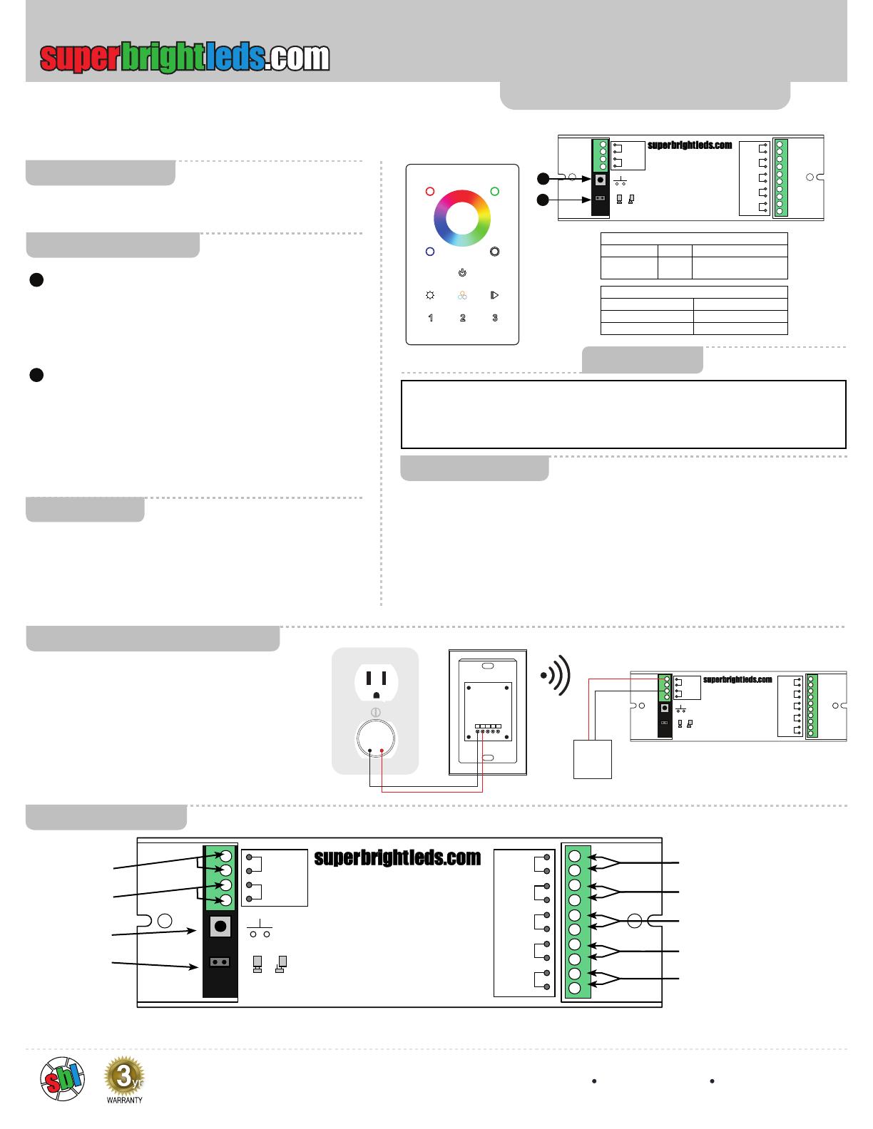
Pairing Controller
1. Pairing Switch
To Pair Wall Switch to Controller, push once and then
push Wall switch. Lights will blink once to indicate linking.
To unpair Wall Switch(es), push and hold until lights blink
twice.
2. Master/Slave Jumper
Set Jumper to Master for main Controller. Master emits
synchronization signal to Slave Controllers. Set Jumper
to Slave to receive synchronization signal from Master
Controller. Use Master for the rst Controller in each zone.
To achieve precise synchronization between Controllers in
one zone, set additional Controllers to slave.
EZD-4C8A Controller
EZD-RGBW3-WM
DC INPUT
OUTPUT
V+
V-
V+
R-
G-
B-
W
12/36VDC
Pairing
Switch
MASTER SLAVE
DC INPUT
OUTPUT
V+
V-
V+
CH1
CH2
CH3
CH4
12/36VDC
Pairing
Switch
MASTER SLAVE
EZD-4C8A
PRI:
Uin=12-36VDC
lin=8.3A
SEC:
Uout=1x(12-36)VDC
Iout=4x8A
Pout=1x(96-288)W
TEMP RANGE: -20ºC-+50ºC
Easy Dimmer Series
EZD-4C8A
PRI:
Uin=12-36VDC
lin=8.3A
SEC:
Uout=1x(12-36)VDC
Iout=4x8A
Pout=1x(96-288)W
TEMP RANGE: -20ºC-+50ºC
Easy Dimmer Series
EZD-RGBW3-WM Remote
Operating Voltage 12~24 VDC
Operating Frequency 868 MHz
FCC ID# 2ACUQ2820
EZD-4C8A Controller
Input Voltage Current Output Wattage
12~36 VDC 4 X 8A 384W(12V) 768W(24V)
1152W(36V)
1
1
2
2
Safety
Set-Up Instructions
Remote
1. Follow illustrated steps below to connect Wall Switch to Power Supply. Connect GND
terminal to negative and connect VIn to positive from power supply.
Controller
1. Make sure power to the Controller is disconnected.
2. Using a small athead screwdriver, loosen the labeled terminal screws visible on the top of
the controller.
3. Matching light strip wires with labeled slots on the Controller, insert wires and tighten
terminal screws. Be sure wire conductor, not wire insulation, is secured in terminal.
4. Turn power on and wait until light strip illuminates. If it does not come on, check light strips
and wiring connections.
• DO NOT install with power applied to controller or switch.
• DO NOT expose the Wall Switch or Controller to moisture.
FCC Statement
This device complies with part 15 of the FCC Rules. Operation is subject to the following two
conditions: (1) This device may not cause harmful interference, and (2) This device must accept
any interference received, including interference that may cause undesired operation. Any changes
or modications in construction of this device which are not expressly approved by the party
responsible for compliance could void the user’s authority to operate the equipment.
Wall Switch Instructions
1. Release Wall Switch control panel from Back Plate
by separating at notch on bottom of Wall Switch and
pivoting away from locking tabs on top of Wall Switch.
2. Connect the wiring from the Wall Switch to the Power
Supply as the diagram shown to the right. Optionally,
connect wired DMX control signal to DMX controllers.
3. Fasten wall switch to existing switch box using
supplied Screws.
4. Align locking tabs on top of Wall Switch Control Panel
to Back Plate and pivot Control panel towards Back
Plate being sure all locking tabs engage fully.
Back of EZD-RGBW3-WM
Power Supply
Power Supply
EZD-4C8A
12-24VDC
GND Vi n D- D+ GND
DC INPUT
OUTPUT
V+
V-
V+
CH1
CH2
CH3
CH4
12/36VDC
Pairing
Switch
MASTER SLAVE
EZD-4C8A
PRI:
Uin=12-36VDC
lin=8.3A
SEC:
Uout=1x(12-36)VDC
Iout=4x8A
Pout=1x(96-288)W
TEMP RANGE: -20ºC-+50ºC
Easy Dimmer Series
DC INPUT
OUTPUT
V+
V-
V+
R-
G-
B-
W
12/36VDC
Pairing
Switch
MASTER SLAVE
DC INPUT
OUTPUT
V+
V-
V+
CH1
CH2
CH3
CH4
12/36VDC
Pairing
Switch
MASTER SLAVE
EZD-4C8A
PRI:
Uin=12-36VDC
lin=8.3A
SEC:
Uout=1x(12-36)VDC
Iout=4x8A
Pout=1x(96-288)W
TEMP RANGE: -20ºC-+50ºC
Easy Dimmer Series
EZD-4C8A
PRI:
Uin=12-36VDC
lin=8.3A
SEC:
Uout=1x(12-36)VDC
Iout=4x8A
Pout=1x(96-288)W
TEMP RANGE: -20ºC-+50ºC
Easy Dimmer Series
Common Anode Output (+)
Channel 2 Output (-)
Channel 1 Output (-)
Channel 3 Output (-)
(+)
(-)
Channel 4 Output (-)
Pairing Switch
Master/Slave
Jumper
Power In
EZD-4C8A Controller
Connection Diagram
User Manual
EZD-RGBW3-WM
with EZD-4C8A controller
4400 Earth City Expy, St. Louis, MO 63045 866-590-3533 superbrightleds.com
Rev Date: V1 07/01/2021


