
1
Video Sound Collaboration System for Huddle Rooms
Operations Guide
Always update the firmware to the latest version.
Please refer to the user’s manual that provides detailed information on how to use the product.
You can download the latest firmware and user’s manual from the following website:
https://uc.yamaha.com/products/video-sound-bar/huddle-room-system/
CS-700
Video Conference System / Système de vidéoconférence
ビデオ会議システム
/
视频会议系统
EN

2
© 2020 YAMAHA UNIFIED COMMUNICATIONS, INC. All rights reserved. No part
of this document may be reproduced in any form or by any means without
express written permission from Yamaha Unified Communications, Inc. Product
specifications are subject to change without notice.
Yamaha CS- 700 Installation and Operation Guide
MN- CS700- 202003 - EN
March 2020 (Rev 1.4 )


4
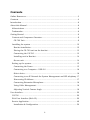
Contents
Online Resources ............................................................................................ 3
Contents ......................................................................................................... 4
Introduction .................................................................................................... 8
About this Manual .......................................................................................... 8
Abbreviations ............................................................................................... 8
Trademarks.................................................................................................. 8
Getting Started ............................................................................................... 9
Content and Component Overview................................................................ 9
CS-700 Unit .............................................................................................. 9
Installing the system .................................................................................. 12
Bracket installation ................................................................................. 12
Placing the CS-700 unit on the bracket ................................................... 13
Connecting the CS-700 ........................................................................... 13
Installing unit in Bracket ......................................................................... 14
Secure unit ............................................................................................. 14
Setting up the system................................................................................. 15
Connecting the Power .............................................................................. 15
Connecting to a Computer – USB 3.0 ...................................................... 16
Select device ............................................................................................ 16
Connecting to an IP Network for System Management and SIP telephony . 17
Discovering IP Address ............................................................................ 17
Connecting Extension Microphone .......................................................... 18
Using Cable Management ........................................................................ 18
Adjusting Vertical Camera Angle ............................................................. 18
User Interface ............................................................................................... 20
CS-700 ...................................................................................................... 20
Web User Interface (Web-UI) ....................................................................... 20
Service Application ..................................................................................... 49
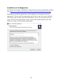
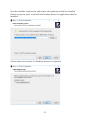
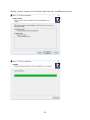
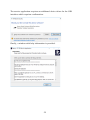
Installation & Configuration .................................................................... 50

5
Using the Service Application .................................................................. 55
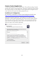
Camera Control Application ....................................................................... 69
Installation & Configuration .................................................................... 69
Using the Camera Control Application ..................................................... 73
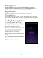
Dialer Application ......................................................................................... 74
Supported Tablets ...................................................................................... 74
Dialer application ....................................................................................... 74
Installing the dialer application .................................................................. 74
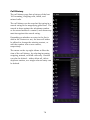
Dialer interface .......................................................................................... 75
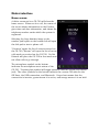
Home screen ........................................................................................... 75
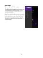
Main Menu .............................................................................................. 76
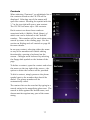
Contacts ................................................................................................. 77
Call History ............................................................................................. 78
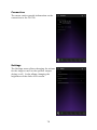
Connection .............................................................................................. 79
Settings ................................................................................................... 79
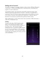
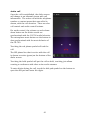
Dialing and call control ........................................................................... 80
Basic Operations ........................................................................................... 85
USB Connected Video Conferencing – BYOD (Bring Your Own Device) ........ 85
USB Connected Video Conferencing – DIR (Device in Room) ....................... 85
Controlling the Video Image ....................................................................... 85
Bluetooth Pairing and Activation ................................................................ 85
Aux-IN Audio Support ................................................................................ 86
Configuring the CS-700................................................................................. 87
Configuring using the Web User Interface ................................................... 87
Configuring using the Service Application................................................... 87
Configuring using a Provisioning Server, Option 66 .................................... 87
Configuring using a Provisioning Server, Option 150 .................................. 88
Provisioning file .......................................................................................... 89
Sample device configuration file ............................................................... 89
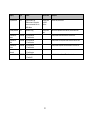
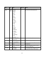
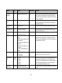
Provisioning file parameters (All Models) ..................................................... 90
Using the Application Programming Interface (API) ................................... 105

6
USB API functions ................................................................................. 105
Telnet / SSH interface ........................................................................... 108
USB/Telnet/SSH CLI Commands .......................................................... 108
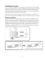
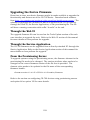
Upgrading the Device Firmware ................................................................... 129
Through the Web UI ................................................................................. 129
Through the Service Application ............................................................... 129
From the Provisioning Server .................................................................... 129
Appendix .................................................................................................... 130
Session Control Functionality Details per Third Party Application ............ 130
Using Windows Computers and MacOS computers ................................ 130
USB 3.0 Extension Cables ........................................................................ 130
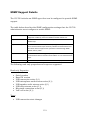
SNMP Support Details .............................................................................. 131
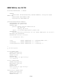
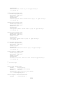
SNMP MIB for the CS-700 ..................................................................... 132
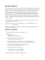
Dial Plan definition................................................................................... 135
Definition of modifiers ........................................................................... 135
Examples .............................................................................................. 136
Optimize Windows for CS-700 Audio ........................................................ 137
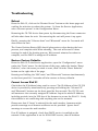
Troubleshooting ....................................................................................... 138
Reboot ................................................................................................... 138
Restore Factory Defaults ....................................................................... 138
Cannot Access Web UI ........................................................................... 138
Lost Password ....................................................................................... 139
Low Camera Image Quality (Far-end video) ............................................ 139
Misaligned Camera Image (Far-end video) .............................................. 140
No Camera Image at Far-end ................................................................. 140
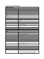
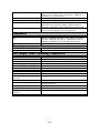
Technical Specifications ........................................................................... 141
Date code ................................................................................................. 143
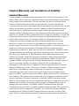
Limited Warranty and Limitation of Liability ................................................ 144
Limited Warranty ..................................................................................... 144
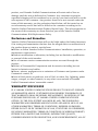
Exclusions and Remedies ......................................................................... 145
WARRANTY EXCLUSION .......................................................................... 145

7
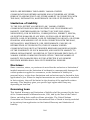
Limitation of Liability ............................................................................... 146
Disclaimer ................................................................................................ 146
Governing Laws........................................................................................ 146
Open Source Software .............................................................................. 147

8
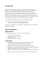
Introduction
Thank you for choosing the Yamaha CS-700 Video Sound Collaboration
System. This Video Sound Collaboration System allows you to provision your
Huddle Room or small multipurpose conference room for all forms of
multimedia Unified Communications using popular video collaboration
applications, as well as independent VOIP-based conference call support. With
Yamaha CS-700 products, video and audio performance is optimized for the
Huddle Room space to deliver class-leading performance, ensuring every word
of the conversation is heard, and every visual nuance is captured.
The complete CS-700 family includes all of the following models
• CS-700AV – Audio/Video/Management Model
• CS-700SP – Audio/Video/SIP/Management Model
Where there is a difference in capabilities or configuration, the document will
highlight that explicitly.
About this Manual
Abbreviations
In this manual, the product names are described as follows.
• Yamaha CS-700: the product
• Microsoft® Windows®: Windows
• macOS®: macOS
• Google® Play Store®: Play Store
Trademarks
• Microsoft and Windows are registered trademarks of Microsoft
Corporation in the United States and other countries.
• Mac and macOS are registered trademarks of Apple Inc.
• Chrome OS is a trademark or registered trademark of Google Inc.
• Bluetooth® is a registered trademark of the Bluetooth SIG and is used by
Yamaha in accordance with a license agreement.
• NFC logo (N-Mark) is a trademark or registered trademark of NFC Forum,
Inc.
• Google and Google Play Store are registered trademarks of Google, LLC

9
Getting Started
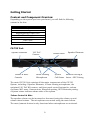
Content and Component Overview
Depending on the system you have purchased, you will find the following
content in the box:
CS-700AV, CS-700SP
CS-700 Sound/Camera Unit
Wall Mounting Bracket
Region Specific Power Cord
Power Supply
Ethernet Cable
USB Cable
Instructions
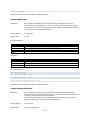
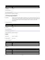
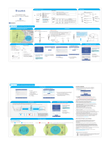
CS-700 Unit
The main CS-700 Unit contains all the major components of the CS-700
System, including 4 Speaker Elements, 4 beam forming microphones, the
optimized 120° FoV HD camera, and front-panel control buttons for: volume
up/down, MIC mute, Camera mute, Bluetooth pairing, NFC Bluetooth pairing.
A system status indicator shows state of the system.
Volume Control & Mute
The speaker volume can be increased or decreased using the volume up and
volume down buttons. The microphones are muted using the mute button.
The mute/unmute button is only functional when microphones are activated.
120° FoV
Camera
Speaker Elements
Beam-Forming
Microphones
Volume & Mute
Controls
Speaker Elements
Camera Mute
Bluetooth Pairing &
Status + NFC Pairing
System
Call Status

10
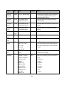
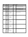
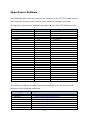
The microphone mute button provides a colored indication of mute status.
Three different microphone states correspond to the color of the LEDs.
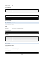
Speaker / Volume State
Volume LED Color
Speaker Volume Buttons Enabled
White
Speaker Volume Buttons Not Enabled
OFF
Microphone/Mute State
MIC LED Color
Active microphones, unmuted
Green
Active microphones, muted
Red
Microphones not active
OFF
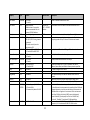
Camera Mute
The camera can be “muted” to prevent active video transmission. Whenever the
Camera Mute button is pressed to mute the video stream, the camera video
stream is substituted with a “pause image” to the far-end.
The camera mute button provides a colored indication of the camera mute
status. The button will light RED when pressed.
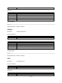
Camera Streaming State
Camera MUTE LED Color
Active camera, unmuted
Green
Active camera, muted
Red
Camera not active
White
Camera software upgrade in process
Slow Flash Red
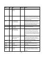
Bluetooth Indicator and NFC Pairing
The Bluetooth indicator shows whenever the CS-700 is in active pairing mode
(flashing blue) or has actively connected with a local Bluetooth device (steady
blue). The NFC paring indicator enables Bluetooth devices capable of NFC
pairing to do so with the CS-700.
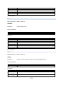
Bluetooth Pairing
Bluetooth LED Color
Bluetooth Enabled, No Connection
White
Bluetooth Initializing
Slow Flash White
System Software Update In Process
Fast Flash White
Bluetooth Pairing In Process
Flash Blue
Bluetooth Enabled, Active Connection
Solid Blue
Bluetooth Service Not Enabled
OFF

11
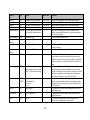
Bluetooth NFC Pairing
NFC LED Color
Bluetooth Enabled +
NFC Pairing Enabled
White
Bluetooth Service, NFC Not Enabled
OFF
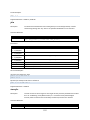
System Call Status Indicator
The System Call Status Indicator located immediately below the Yamaha logo
shows whenever the CS-700 is actively engaged in a call or not. It also shows
whenever a hardware failure has been detected by turning RED. The following
color codes have been assigned:
Call Status Indicator
System Status LED Color
Not in Call (BT, VOIP), or
USB Connected but
NO Video/Audio Stream
White
CS-700 Unit OFF or Booting-UP
OFF
Call Active (BT, VOIP), or
USB Connected and Video/Audio
stream active.
Green
Call on Hold
Flashing Green
Hardware Failure Detected
Red

12
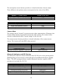
Installing the system
The CS-700 unit is designed to be mounted to the huddle-room wall using the
bracket included with the unit. The recommended mounting location is directly
adjacent to the display unit, typically just below it, with an optimal distance
above the conference room table of 10-18 inches (25 – 45 cm). This provides
an optimum camera perspective for the far-end.
If the CS-700 unit is used in conjunction with a touch-screen or electronic
white board, the preferred installation location is immediately above the screen.
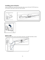
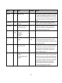
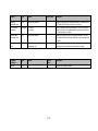
Bracket installation
Install the bracket with 4 appropriate screws on the wall, spacing two pair of
screws as far apart as possible. Ensure that the bracket is tight to the wall or
the spacers to avoid vibration. If installed below the display ensure that the
distance is big enough to fit the CS-700 unit. You can adjust the depth of the
installation by using the appropriate number of spacers (0-2) on each side.
Maximum mounting height is 2m / 6’ 8” from the floor. Always use 4 screws.
0x, 1x, 2x
≥ 3 ¾ in /
95 mm

13
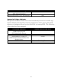
Placing the CS-700 unit on the bracket
Position the CS-700 in such a way that the two hooks in the front of the
bracket fit into the cavities on the lower part of the CS-700. Ensure that the
CS-700 is safely held by the hooks.
Connecting the CS-700
Once the CS-700 is safely positioned on the hooks of the bracket, connect the
power cable and the USB cable to the CS-700 as shown. If it is planned to
manage the CS-700 using the web browser or as a SIP phone (-SP, -DS
models), also connect the network cable into the corresponding connector.
Secure the cables using the provided cable ties to the CS-700 unit.

14
Installing unit in Bracket
Once all cables are correctly connected and secured, tilt the CS-700 back on
the bracket and push it pack into the bracket.
Secure unit
Secure the CS-700 unit in the bracket with the provided machine screws.

15
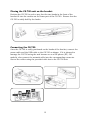
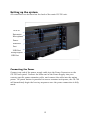
Setting up the system
All connectors can be found on the back of the main CS-700 unit.
Connecting the Power
Connect one end of the power supply cable into the Power Connector on the
CS-700 back panel. Connect the other end of the Power Supply into your
country-specific power extension cable, and connect the cable into the mains
power. No power button is provided to ensure constant unit power; the CS-700
will immediately begin the boot-up sequence once the power connection is fully
made.
AUX-In
Power
Ethernet
Port
USB Port
Extension
Microphone
Multipurpose
USB Port

16
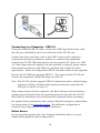
Connecting to a Computer – USB 3.0
Using the included USB 3.0 cable, connect the USB Type-B side of the cable
into the port identified by the icon on the back of the CS-700 unit.
Connect the other end of the cable to the USB 3.0 port on the computer
running the third party softphone, webinar, or conferencing application.
Connect the CS-700 USB cable directly into the attached PC device. If a USB
3.0 cable longer than the length of the one provided is required, please ensure
that extension cables are fully USB 3.0 compliant and certified for video
applications. Find a list of approved USB 3.0 extension cables in the appendix.
Be sure the PC USB Port supports USB 3.0. The camera of the CS-700 will
send an uncompressed 1080p HD image over HD 3.0.
Note: The CS-700 will also support USB 2.0 connections with a reduced image
resolution of 360p. If limited video quality is observed, verify that the
USB port on the PC is truly 3.0.
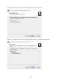
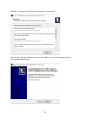
When connecting to the Host computer, the Host OS may need to install pre-
existing drivers provided with the operating system for use with the CS-700.
Wait until the installation of such drivers has completed before continuing.
For optimal audio performance when using a Windows computer, please follow
the instructions in the appendix section. No additional configuration is
required when using macOS or Chrome OS devices.
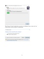
Select device
In your operating system select the “Yamaha AudioVideo Device” as your
default audio playback and recording device.

17
In your unified communications application, select the CS-700 as the Video
device.
Connecting to an IP Network for System Management and SIP
telephony
Note, the CS-700 does not require a network connection in order to operate.
The Plug-and-play nature of the USB connection is sufficient to enable the CS-
700 to function. However, if any network management features, including
network configuration, access to Web-UI, SNMP, and any SIP/VOIP
connectivity (model CS-700SP) is required, an IP Network Connection is
necessary.
Connect one end of the Ethernet cable into the network connection port on the
bottom of the base unit using the network port. Press the Ethernet connector
until it clicks into place. Connect the other end of the Ethernet cable into a
jack providing network access. The CS-700 does not support being powered
over PoE and requires power from the power supply.
If the Ethernet cable needs to be removed, depress the lever on the connector
and pull the cable out gently. Using force when removing this cable may
damage the cable and render it useless.
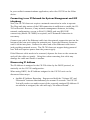
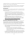
Discovering IP Address
The IP Address is assigned to the CS-700 either by the DHCP protocol, or
statically via the CS-700 configuration.
When using DHCP, the IP Address assigned to the CS-700 unit can be
discovered three ways.
• Audible IP Address Reporting. Depress and hold the “Volume-UP” and
“Bluetooth” buttons simultaneously for around 5 seconds. The CS-700
Unit will produce an audio-report of the currently assigned IP Address. If
no address is assigned, the unit will reply “No address found”.

18
• Connected PC via USB Cable, operating the “Service Application”. The
Service Application will provide a method of identifying the current IP
and MAC addresses of the CS-700 unit. The Service Application is used
by System Administrators.
• Interrogation of DHCP Server Leased IP Address List, and association
with MAC Addresses. Known CS-700 MAC addresses will provide a
remotely managed estate of CS-700 units to be mapped to IP Addresses.
Connecting Extension Microphone
The CS-700 offers wired or wireless Extension Microphone to extend reach of
microphone pick-up as an option. Connect the extension microphone into the
CS-700 connector where indicated. Only the Yamaha extension microphone is
qualified for operation on this port. The Wired Extension Microphone includes
a 25-feet (7.50 meter) cable.
Using Cable Management
To help secure the cables connected to the CS-700 main unit, indents are
provided on the back casing to support the included “hook-and-loop” cable ties.
Cables can be secured and tied-off on the back of the CS-700 to ensure robust
cable connections.
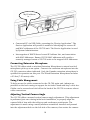
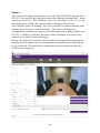
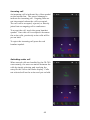
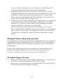
Adjusting Vertical Camera Angle
The CS-700 offers a manual vertical camera angle adjustment. This adjustment
is performed just once during initial unit installation, to properly align the
camera field of view with the table-top and conference participants. The
adjustment is made using a small/medium screwdriver inserted and pressed
into the adjustment hole on the left-side of the camera, then rotate the camera
My IP address
is …

19
assembly up or down to the desired angle. As the camera rotates, mechanical
detents within the camera mechanism will lock the camera into position. You
will hear clicking sounds as the detents engage.
Important Note - When adjusting the manual vertical camera angle do not force or
over stress the mechanism as this could damage the camera mechanism. The
mechanism will stop when it reaches the maximum adjustment, do not apply force
beyond the maximum adjustment. Damage to the camera mechanism caused by
excessive manual force will void warranty.
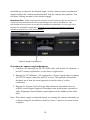
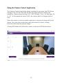
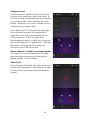
Procedure for camera angle adjustment
1. Connect a PC through the CS-700 USB cable, and enable UC software, a
local PC camera application, or the Service Application.
2. Engage the UC Software / PC application / Service Application to display
the CS-700 camera onto the local PC screen. This provides immediate
feedback as to how the room appears on the far-side of a video
conference.
3. Engage the Camera Vertical Angle Adjustment as described above to
achieve a well-aligned capture of meeting room participants around the
table. Alignment should balance participants in the middle of the video
shot.
Note: The camera angle is adjusted simply by rotating the camera assembly up
or down using the screwdriver shaft as a lever – there is no actual screw
to adjust.
Camera Angle Adjustment

20
User Interface
CS-700
The CS-700 unit provides volume up, volume down, audio mute, camera mute,
Bluetooth Pairing and Bluetooth NFC controls and indicators on the front of
the unit.
Volume Up/Down buttons affect the sound from the CS-700, with
corresponding increasingly or decreasingly loud “beeps” occurring with each
press.
The CS-700 will default the sound level to a pre-set value following each new
USB connection session.
Mute status is reflected on the color of the Mute Buttons.
• Audio microphone Mute not-enable is green, while enabled is red. The
button will be OFF whenever the button is disabled as a configuration
option.
• Camera Mute not-enabled is green, while enabled is red. The button will
glow white whenever the Camera is not active, and will be OFF whenever
the button is disabled as a configuration option.
CS-700 front panel audio controls (Volume, Mute) are synchronized with audio
controls on the attached Computer Operating System, enabling control from
both locations. See the section “Session Control Functionality Details” in the
appendix for more information.
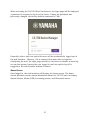
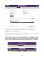
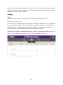
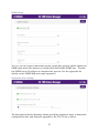
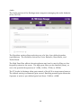
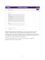
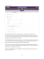
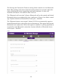
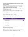
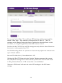
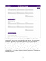
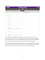
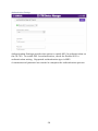
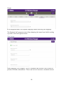
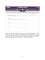
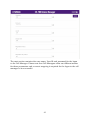
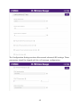
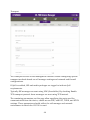
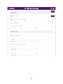
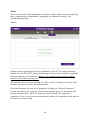
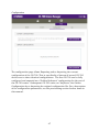
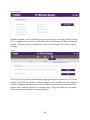
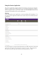
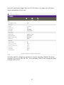
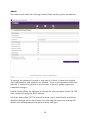
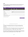
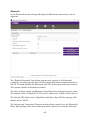
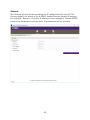
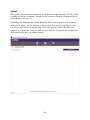
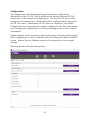
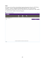
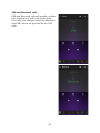
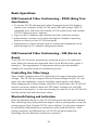
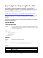
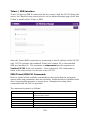
Web User Interface (Web-UI)
The CS-700 supports an internal webserver and web-based user interface (i.e.
Web-UI), providing configuration and operations access to the unit using a
standard web browser. This interface is intended for use by System
Administrators, not end-users, and is only available through the IP network
interface. Using the IP address of the CS-700, the Web-UI can be accessed
using a web browser by entering the IP address in the URL line. Supported
browsers are Microsoft Edge, Google Chrome, and Mozilla Firefox.
Strona się ładuje...
Strona się ładuje...
Strona się ładuje...
Strona się ładuje...
Strona się ładuje...
Strona się ładuje...
Strona się ładuje...
Strona się ładuje...
Strona się ładuje...
Strona się ładuje...
Strona się ładuje...
Strona się ładuje...
Strona się ładuje...
Strona się ładuje...
Strona się ładuje...
Strona się ładuje...
Strona się ładuje...
Strona się ładuje...
Strona się ładuje...
Strona się ładuje...
Strona się ładuje...
Strona się ładuje...
Strona się ładuje...
Strona się ładuje...
Strona się ładuje...
Strona się ładuje...
Strona się ładuje...
Strona się ładuje...
Strona się ładuje...
Strona się ładuje...
Strona się ładuje...
Strona się ładuje...
Strona się ładuje...
Strona się ładuje...
Strona się ładuje...
Strona się ładuje...
Strona się ładuje...
Strona się ładuje...
Strona się ładuje...
Strona się ładuje...
Strona się ładuje...
Strona się ładuje...
Strona się ładuje...
Strona się ładuje...
Strona się ładuje...
Strona się ładuje...
Strona się ładuje...
Strona się ładuje...
Strona się ładuje...
Strona się ładuje...
Strona się ładuje...
Strona się ładuje...
Strona się ładuje...
Strona się ładuje...
Strona się ładuje...
Strona się ładuje...
Strona się ładuje...
Strona się ładuje...
Strona się ładuje...
Strona się ładuje...
Strona się ładuje...
Strona się ładuje...
Strona się ładuje...
Strona się ładuje...
Strona się ładuje...
Strona się ładuje...
Strona się ładuje...
Strona się ładuje...
Strona się ładuje...
Strona się ładuje...
Strona się ładuje...
Strona się ładuje...
Strona się ładuje...
Strona się ładuje...
Strona się ładuje...
Strona się ładuje...
Strona się ładuje...
Strona się ładuje...
Strona się ładuje...
Strona się ładuje...
Strona się ładuje...
Strona się ładuje...
Strona się ładuje...
Strona się ładuje...
Strona się ładuje...
Strona się ładuje...
Strona się ładuje...
Strona się ładuje...
Strona się ładuje...
Strona się ładuje...
Strona się ładuje...
Strona się ładuje...
Strona się ładuje...
Strona się ładuje...
Strona się ładuje...
Strona się ładuje...
Strona się ładuje...
Strona się ładuje...
Strona się ładuje...
Strona się ładuje...
Strona się ładuje...
Strona się ładuje...
Strona się ładuje...
Strona się ładuje...
Strona się ładuje...
Strona się ładuje...
Strona się ładuje...
Strona się ładuje...
Strona się ładuje...
Strona się ładuje...
Strona się ładuje...
Strona się ładuje...
Strona się ładuje...
Strona się ładuje...
Strona się ładuje...
Strona się ładuje...
Strona się ładuje...
Strona się ładuje...
Strona się ładuje...
Strona się ładuje...
Strona się ładuje...
Strona się ładuje...
Strona się ładuje...
Strona się ładuje...
Strona się ładuje...
Strona się ładuje...
Strona się ładuje...
Strona się ładuje...
Strona się ładuje...
-
 1
1
-
 2
2
-
 3
3
-
 4
4
-
 5
5
-
 6
6
-
 7
7
-
 8
8
-
 9
9
-
 10
10
-
 11
11
-
 12
12
-
 13
13
-
 14
14
-
 15
15
-
 16
16
-
 17
17
-
 18
18
-
 19
19
-
 20
20
-
 21
21
-
 22
22
-
 23
23
-
 24
24
-
 25
25
-
 26
26
-
 27
27
-
 28
28
-
 29
29
-
 30
30
-
 31
31
-
 32
32
-
 33
33
-
 34
34
-
 35
35
-
 36
36
-
 37
37
-
 38
38
-
 39
39
-
 40
40
-
 41
41
-
 42
42
-
 43
43
-
 44
44
-
 45
45
-
 46
46
-
 47
47
-
 48
48
-
 49
49
-
 50
50
-
 51
51
-
 52
52
-
 53
53
-
 54
54
-
 55
55
-
 56
56
-
 57
57
-
 58
58
-
 59
59
-
 60
60
-
 61
61
-
 62
62
-
 63
63
-
 64
64
-
 65
65
-
 66
66
-
 67
67
-
 68
68
-
 69
69
-
 70
70
-
 71
71
-
 72
72
-
 73
73
-
 74
74
-
 75
75
-
 76
76
-
 77
77
-
 78
78
-
 79
79
-
 80
80
-
 81
81
-
 82
82
-
 83
83
-
 84
84
-
 85
85
-
 86
86
-
 87
87
-
 88
88
-
 89
89
-
 90
90
-
 91
91
-
 92
92
-
 93
93
-
 94
94
-
 95
95
-
 96
96
-
 97
97
-
 98
98
-
 99
99
-
 100
100
-
 101
101
-
 102
102
-
 103
103
-
 104
104
-
 105
105
-
 106
106
-
 107
107
-
 108
108
-
 109
109
-
 110
110
-
 111
111
-
 112
112
-
 113
113
-
 114
114
-
 115
115
-
 116
116
-
 117
117
-
 118
118
-
 119
119
-
 120
120
-
 121
121
-
 122
122
-
 123
123
-
 124
124
-
 125
125
-
 126
126
-
 127
127
-
 128
128
-
 129
129
-
 130
130
-
 131
131
-
 132
132
-
 133
133
-
 134
134
-
 135
135
-
 136
136
-
 137
137
-
 138
138
-
 139
139
-
 140
140
-
 141
141
-
 142
142
-
 143
143
-
 144
144
-
 145
145
-
 146
146
-
 147
147
-
 148
148
-
 149
149


w innych językach
- čeština: Yamaha CS-700 Uživatelská příručka
- español: Yamaha CS-700 Guía del usuario
- italiano: Yamaha CS-700 Guida utente
- Deutsch: Yamaha CS-700 Benutzerhandbuch
- português: Yamaha CS-700 Guia de usuario
- français: Yamaha CS-700 Mode d'emploi
- English: Yamaha CS-700 User guide
- dansk: Yamaha CS-700 Brugervejledning
- Nederlands: Yamaha CS-700 Gebruikershandleiding
- română: Yamaha CS-700 Manualul utilizatorului
Powiązane artykuły
-
Yamaha CS-700 instrukcja
-
-
-
-
-
-
Yamaha CS-500 instrukcja
-
Yamaha YVC-200 instrukcja
-
-
Inne dokumenty
-
Adastra PS50-B Instrukcja obsługi
-
 WAVLINK WN570HP2 instrukcja
-
Panasonic RP-BTD10E-K Instrukcja obsługi
-
-
fiodio F-SG61 Instrukcja obsługi
-
SEWOO LK-P20ll Instrukcja obsługi
-
Valcom VRCPA Configuration Guide
-
Manta rainbow eye MA417 Instrukcja obsługi
-
Mi Router 4C Instrukcja obsługi
-
