clage E-convenience Instant Water Heater DEX Next instrukcja
- Typ
- instrukcja


I
DEX Next
A1
A3
A2
A4
Abbildungsverzeichnis / List of figures / Liste des figures / Lijst van figuren / Lista de Figuras / Lista de Figuras / Lista liczb / Список рисунков / Seznam čísel /
Zoznam čísiel / Списък с фигури / Lista figura
7
4
6
5
2
1
3

II
CLAGE
v
16
17
18
24
23
22
13
15
4
5
3
3
8
1
14
10
9
2
6
21
19
20
7
1211
C1
Abbildungsverzeichnis / List of figures / Liste des figures / Lijst van figuren / Lista de Figuras / Lista de Figuras / Lista liczb / Список рисунков / Seznam čísel /
Zoznam čísiel / Списък с фигури / Lista figura

III
DEX Next
E1
E3
E2
F1
12
5
3
4
A
SDB
Abbildungsverzeichnis / List of figures / Liste des figures / Lijst van figuren / Lista de Figuras / Lista de Figuras / Lista liczb / Список рисунков / Seznam čísel /
Zoznam čísiel / Списък с фигури / Lista figura
100
170
468 363
56
96
239
D1 D2
D

IV
CLAGE
G2
F3
F4
G3
0
1
G1
(a)
1
0
F5
Abbildungsverzeichnis / List of figures / Liste des figures / Lijst van figuren / Lista de Figuras / Lista de Figuras / Lista liczb / Список рисунков / Seznam čísel /
Zoznam čísiel / Списък с фигури / Lista figura
F2
STB
(c)(b)

2
DE
DEX Next
Inhaltsverzeichnis
2. Umwelt und Recycling
Dieses Produkt wurde klimaneutral nach Scope 1 + 2 hergestellt. Wir empfehlen den Bezug von
100%igem Ökostrom, um den Betrieb ebenfalls klimaneutral zu gestalten.
Entsorgung von Transport- und Verpackungsmaterial: Für einen reibungslosen Transport
ist Ihr Produkt sorgfältig verpackt. Die Entsorgung des Transportmaterials erfolgt über den
Fachhandwerker oder den Fachhandel. Führen Sie die Verkaufsverpackung nach Materialien
getrennt über eines der dualen Systeme Deutschlands in den Wertstoffkreislauf zurück.
Entsorgung von Altgeräten: Ihr Produkt wurde aus hochwertigen,
wiederverwendbaren Materialien und Kompo nenten hergestellt. Die mit dem
Symbol der durchgestrichenen Mülltonne gekennzeichneten Produkte müssen
am Ende ihrer Lebensdauer getrennt vom Hausmüll entsorgt werden. Bringen
Hinweis: Die beiliegenden Sicherheitshinweise sind vor der Installation, der Inbetrieb nahme und der Nutzung sorgfältig und vollstän-
dig durchzulesen und für das weitere Vorgehen, sowie den Gebrauch zu beachten!
Gebrauchsanleitung
Der E-Komfortdurchlauferhitzer DEX Next ist ein elektronisch geregelter Durchlauferhitzer
mit grafikfähigem E-Paper-Display und Sensortasten zur komfortablen und sparsamen
Wasserversorgung einer oder mehrerer Zapfstelle(n).
Die Elektronik regelt die Leistungsaufnahme in Abhängigkeit von der gewählten
Auslauftemperatur, der jeweiligen zulauftemperatur und auch der Durchflussmenge, um die ein-
gestellte Temperatur gradgenau zu erreichen und auch bei Wasser druck schwankungen konstant
zu halten. Die gewünschte Auslauftemperatur kann über die Sensortasten von 20 °C bis 60 °C
eingegeben und auf dem E-Paper-Display abgelesen werden.
1. Gerätebeschreibung
Sobald Sie das Warmwasserventil an der Armatur öffnen, schaltet sich der Durchlauf erhitzer
automatisch ein. Beim Schließen der Armatur schaltet sich das Gerät automatisch wieder aus.
Die Bedienung des Durchlauferhitzers erfolgt entweder direkt am Gerät oder mit einer optionalen
Funkfernbedienung.
Abbildungsverzeichnis
Gebrauchsanleitung
. Gerätebeschreibung .............................................................
. Umwelt und Recycling ............................................................
. Gebrauch ......................................................................
Hauptsteuerung ................................................................
Hauptmenü ....................................................................
Entlüften nach Wartungs arbeiten ..................................................
Reinigung und Pflege. . . . . . . . . . . . . . . . . . . . . . . . . . . . . . . . . . . . . . . . . . . . . . . . . . . . . . . . . . . .
. Selbsthilfe bei Problemen und Kundendienst .........................................
. Produktdatenblatt nach Vorgabe der EU Verordnungen - / / .............
Montageanleitung
. Übersichtsdarstellung ............................................................
. Technische Daten ...............................................................
. Abmessungen ...................................................................
. Installation .....................................................................
Wasseranschlussstücke installieren ................................................
Montageort ....................................................................
Gerät montieren ................................................................
Wandhalter montieren ...........................................................
. Elektroanschluss ................................................................
Elektroanschluss unten ..........................................................
Schaltplan .....................................................................
Bauliche Voraussetzungen ........................................................
. Erstinbetriebnahme ..............................................................
Duschanwendung ...............................................................
Leistungsumschaltung ...........................................................
Erneute Inbetriebnahme .........................................................
Sperrfunktion ..................................................................
. Wartungsarbeiten. . . . . . . . . . . . . . . . . . . . . . . . . . . . . . . . . . . . . . . . . . . . . . . . . . . . . . . . . . . . . . . .
Reinigung und Wechsel des Filtersiebes im Anschlussstück bei Unterputzanschluss ........
Reinigung und Wechsel des Filtersiebes bei Aufputzanschluss ..........................
Die mit dem Gerät gelieferten Unterlagen sind sorgfältig aufzubewahren.
Die Zulauftemperatur kann bis zu 70 °C betragen, so dass auch der Betrieb zur Nacherwärmung,
z.B. in Solaranlagen, möglich ist.
Der Durchlauferhitzer kann in Kombi nation mit einem externen Last abwurf relais für elektroni-
sche Durch lauf erhitzer betrieben werden (Details siehe Montageanleitung).
Sie dieses Gerät daher zu uns als Hersteller oder zu einer der kommunalen Sammelstellen, die
gebrauchte Elektronikgeräte wieder dem Wert stoff kreislauf zuführen. Diese ordnungsgemäße
Entsorgung dient dem Umweltschutz und verhindert mögliche schädliche Auswirkungen auf
Mensch und Umwelt, die sich aus einer unsachgemäßen Handhabung der Geräte am Ende ihrer
Lebensdauer ergeben könnten. Genauere Infor ma tionen zur Entsorgung erhalten Sie bei der
nächstgelegenen Sammelstelle bzw. dem Recyclinghof oder Ihrer Gemeindeverwaltung.
Geschäftskunden: Wenn Sie Geräte entsorgen möchten, treten Sie bitte mit Ihrem Händler oder
Lieferanten in Kontakt. Diese halten weitere Informationen für Sie bereit.
Bei Entsorgung außerhalb Deutschlands beachten Sie auch die örtlichen Vorschriften und
Gesetze.
Geräteregistrierung
Registrieren Sie Ihr Gerät online auf unserer Webseite und profitieren Sie von unseren Serviceleistungen im Garantiefall.
Ihre vollständigen Daten helfen unserem Kundendienst Ihr Anliegen schnellstmöglich zu bearbeiten.
Für die Onlineregistrierung folgen Sie einfach dem unten stehenden Link oder nutzen Sie den QR-Code mit Ihrem Smartphone oder Tablet.
https://partner.clage.com/de/service/geraeteregistrierung/

CLAGE
3
DE
Hauptsteuerung
Das E-Paper-Display wechselt nach ca. 60 Sekunden ohne Tastendruck automatisch in die
Hauptansicht.
Durch einfaches Tippen auf eine der Sensortasten können verschiedene Nutzerprofile und
Anwendungen ausgewählt oder Temperaturänderungen vorgenommen werden.
3. Gebrauch
Temperaturanzeige
Der Skalenring wird bei steigender Temperatureinstellung aufgefüllt. Zusätzlich wird die
Solltemperatur in °C in der Displaymitte angezeigt.
Temperatureinstellung
Die Wunschtemperatur kann über die zwei mittleren Sensortasten in einem Bereich von 20 °C
bis 60 °C gewählt werden. Einmaliges Tippen ändert die Temperatur um 1 °C, im Komfortbereich
zwischen 35 °C und 43 °C um 0,5 °C. Wird die Temperatur unter 20 °C eingestellt, erscheint das
Symbol in der Temperaturanzeige und das Gerät schaltet die Heizfunktion ab.
Nutzerauswahl
Es können bis zu vier Nutzerprofile angepasst werden. Jeder Nutzer hatdie Möglich keit, sich
seine Wunschtemperaturen für die verschiedenen Anwendungs bereiche in seinem Profil zu
speichern. Die Nutzerprofile können durch Tippen auf die linke Sensortaste aufgelistet und dann
über die jeweilige Sensortaste unter den Profilbildern gewählt werden
(Profil individualisieren
siehe Abschnitt »Nutzer«)
(Abb. A2)
.
Anwendungen
Hier können bereits voreingestellte Anwendungen ausgewählt werden. Durch Tippen der
Sensortaste unter der Anzeige öffnet sich die Auswahl (Abb. A3). Tippen auf die Sensortaste unter
einer der Anwendungen aktiviert diese.
Die Anwendungen sind werkseitig auf die folgenden Temperaturwerte ein gestellt:
Handwäsche=35 °C, Dusche=38 °C, Badewanne=40 °C,
Heißwasser=48 °C.
Um eigene Temperaturwerte zu speichern, wählen Sie eine Anwendung und stellen die gewünsch-
te Temperatur ein. Anschließend tippen und halten Sie die Sensortaste unter Ihrem Profilbild oder
unter der Anwendung für zwei Sekunden gedrückt.
Statusanzeige oben
Bediensperre aktiv (PIN)
Die Zulauftemperatur liegt über dem Sollwert (Gerät heizt nicht)
Optionale Funkfernbedienung bzw. Home Server ist installiert. Das Gerät kann fernge-
steuert werden.
Statusanzeige unten
Anzeigebereich für Funktionen, welche eine Bestätigung vom Nutzer verlangen oder im Gebrauch
von hoher Bedeutung sind.
Wartung: Das Gerät hat einen Fehler erkannt. Weitere Informationen erhalten Sie im
Hauptmenü unter »Info«.
Maximaltemperatur erreicht: Die Temperatur lässt sich nicht weiter erhöhen, da
die eingestellte Temperaturgrenze erreicht wurde. Die Temperaturgrenze kann im
Hauptmenü unter »Einstellungen« geändert werden.
Heizung aktiviert: Das Symbol erscheint sobald Wasser durch das Gerät erwärmt wird.
Leistungsgrenze: Die Leistung des Gerätes reicht nicht aus, um die aktuell fließende
Warmwassermenge auf die Wunschtemperatur zu erwärmen. Reduzieren Sie die
Warmwassermenge an der Armatur.
Pos. Funktion
1 Statusanzeige oben
2 Nutzer
3 Menütaste
4 Temperaturanzeige
5 Statusanzeige unten
6 Anwendungen
7 Sensortasten
Displayanzeigen (Abb. A1)
Hauptmenü
Über die Menütaste gelangen Sie in das Hauptmenü. Alle Funktionsmenüs und Speicherwerte
des Gerätes können von hier aus ausgewählt werden
(Abb. A4)
.
Weitere Informationen finden Sie in der online erhältlichen Gebrauchs-
und Montageanleitung. Folgen Sie bitte dem unten stehenden Link oder
nutzen Sie den QR-Code mit Ihrem Smartphone oder Tablet.
https://www.clage.de/links/gma/DEX-Next-GMA-9120-34382
Dieser Durchlauferhitzer ist mit einer auto matischen Luftblasenerkennung
ausgestattet, die ein versehentliches Trocken laufen verhindert. Trotzdem
muss das Gerät vor der erst en Inbetriebnahme entlüftet werden. Nach
jeder Entleerung (z.B. nach Arbeiten in der Wasser installation, wegen
Frostgefahr oder nach Reparaturen am Gerät) muss das Gerät vor der
Wiederinbetriebnahme erneut entlüftet werden.
1. Trennen Sie den Durchlauferhitzer vom Netz, indem Sie die Sicherungen aus schalten.
2. Schrauben Sie den Strahlregler an der Entnahmearmatur ab und öffnen Sie zunächst das
Kaltwasserzapfventil, um die Wasserleitung sauber zu spülen und eine Verschmutzung des
Gerätes oder des Strahlreglers zu vermeiden.
3. Öffnen und schließen Sie danach mehrfach das zugehörige Warm wasser zapfventil, bis keine
Luft mehr aus der Leitung austritt und der Durchlauferhitzer luftfrei ist.
4. Erst dann dürfen Sie die Stromzufuhr zum Durchlauferhitzer wieder einschalten und den
Strahlregler wieder einschrauben.
5. Nach ca. zehnSekunden kontinuierlichem Wasserfluss aktiviert das Gerät die Heizung.
Entlüften nach Wartungs arbeiten
• Kunststoffoberflächen und Sanitär armaturen nur mit einem feuchten Tuch abwischen. Keine
scheuernden, lösungsmittel- oder chlorhaltigen Reinigungsmittel verwenden.
• Für eine gute Wasserdarbietung soll ten Sie die Entnahme armaturen (z.B. Strahl regler und
Duschköpfe) regel mäßig ab schrauben und reinigen. Lassen Sie alle drei Jahre die elektro-
und wasser seitigen Bauteile durch einen an er kann ten Fachhandwerks betrieb über prüfen,
um die einwand freie Funktion und Betriebs sicherheit jederzeit zu gewähr leisten.
Reinigung und Pflege

4
DE
DEX Next
Dieser Durchlauferhitzer wurde sorgfältig hergestellt und vor der Auslieferung mehr fach über-
prüft. Tritt ein Problem auf, so liegt es oft nur an einer Kleinigkeit. Schalten Sie zunächst die
Sicherungen aus und wieder ein, um die Elektronik »zurückzusetzen«. Prüfen Sie dann, ob Sie
das Problem mit Hilfe der folgenden Tabelle selbst beheben können. Sie vermeiden dadurch die
Kosten für einen unnötigen Kunden diensteinsatz.
Reparaturen dürfen nur von aner kann ten Fach hand werks betrieben durchgeführt werden.
Wenn sich ein Fehler an Ihrem Gerät mit dieser Tabelle nicht beheben lässt, wenden Sie sich bitte
an den Werks kunden dienst. Halten Sie die Daten des Geräte typen schildes bereit!
4. Selbsthilfe bei Problemen und Kundendienst
CLAGE GmbH
Werkskundendienst
Pirolweg 4
21337 Lüneburg
Deutschland
Fon: +49 4131 8901-400
E-Mail: [email protected]
DEX Next
Problem Ursache Abhilfe
Wasser bleibt kalt,
Display zeigt Screen
»Stromausfall«
Haussicherung ausgelöst Sicherung erneuern oder einschalten
Sicherheits druck schalter hat ausgelöst Kundendienst informieren
Wasser bleibt kalt,
in der Anzeige
erscheint das
Wartungssymbol
Das Gerät hat eine Störung erkannt
Sicherungen aus- und wieder einschalten. Wenn
Fehler meldung weiterhin besteht, Kundendienst
informieren
Warmwasser durchfluss wird
schwächer
Auslaufarmatur verschmutzt oder
verkalkt Strahlregler, Duschkopf und Siebe reinigen
Zulauffiltersieb verschmutzt oder
verkalkt Filtersieb von Kundendienst reinigen lassen
Gewählte Temperatur wird nicht
erreicht
Leistungsgrenze erreicht Warmwasserdurchfluss an der Armatur redu-
zieren
Kaltwasser wird an der Armatur bei-
gemischt
Nur Warmwasser zapfen, Temperatur für den
Gebrauch einstellen, Auslauftemperatur prüfen
Sensortasten reagieren nicht richtig Displayglas ist nass Display mit einem weichen Tuch trocken wischen
5. Produktdatenblatt nach Vorgabe der EU Verordnungen - 812/2013 814/2013
a b c d e f h i
b.1 b.2 ηWH AEC °C LWA
%kWh dB(A)
CLAGE DEX Next 5E-270V-3D S A 38 479 60 15
Erläuterungen
aName oder Warenzeichen
b.1 Gerätebezeichnung
b.2 Gerätetyp
cLastprofil
dKlasse Warmwasserbereitungs-Energieeffizienz
eWarmwasserbereitungs-Energieeffizienz
fJährlicher Stromverbrauch
gAlternatives Lastprofil, die entsprechende Warmwasserbereitungs-Energieeffizienz und der entsprechende jährliche Stromverbrauch, sofern verfügbar.
hTemperatureinstellungen des Temperaturreglers des Warmwasserbereiters
iSchallleistungspegel in Innenräumen
Zusätzliche Hinweise
Alle bei der Montage, Inbetriebnahme, Gebrauch und Wartung des Warmwasserbereiters zu treffenden besonderen Vorkehrungen sind in der Gebrauchs- und
Installationsanweisung zu finden.
Alle angegebenen Daten wurden auf Grundlage der Vorgabe der europäischen Richtlinien ermittelt. Unterschiede zu Produktinformationen, die an anderer Stelle angeführt
werden, basieren auf unterschiedlichen Testbedingungen.
Der Energieverbrauch wurde nach einem standardisierten Verfahren nach EU-Vorgaben ermittelt. Der reale Energiebedarf des Gerätes hängt von der individuellen
Anwendung ab.

CLAGE
5
DE
1. Übersichtsdarstellung
Montageanleitung
Pos. Funktion
1 Geräteunterteil
2 Temperaturbegrenzer (STB)
3 Temperaturfühler
4 Rückflussverhinderer
5 Durchflussgeber
6 Heizelement
7 Sicherheitsdruckbegrenzer SDB
8 Auslaufrohr
9Warmwasser anschluss stück
10 Durchfluss mengen regler 8 l/min
11 G½Zoll Einschraubnippel
12 Durchführungstülle
Pos. Funktion
13 Spritzwasserschutztülle
14 Wandhalter
15 DEX Next Gerätehaube
16 Verbindungsrohr
17 Elektronikabdeckung
18 Elektronik
19 Anschlussklemme
20 Bedienfeld mit Klapphalter
21 Zulaufrohr
22 Feinfilter
23 Kaltwasseranschlussstück
24 Rahmen
Typ DEX Next
Energieeffizienzklasse A *)
Nennleistung / -strom 18 kW..27 kW (26 A..39 A)
Gewählte/r Leistung / Strom 18 kW / 26 A 16,2 kW / 25 A 21 kW / 30 A 19 kW / 29 A 24 kW / 35 A 21,7 kW / 33 A 27 kW / 39 A 24,4 kW / 37 A
Nennspannung 400 V 380 V 400 V 380 V 400 V 380 V 400 V 380 V
Elektroanschluss 3~ / PE
Erforderlicher Leiterquerschnitt 1) 4,0 mm24,0 mm26,0 mm26,0 mm2
Warmwasserleistung (l/min)
max. bei t = 28 K
max. bei t = 38 K
9,2 2)
6,8
10,7 2)
7,9
12,3 2)
9,0 2)
13,8 2)
10,2 2)
Nenninhalt 0,4 l
Nennüberdruck 1,0 MPa (10 bar)
Anschlussart druckfest / drucklos
Heizsystem Blankdraht-Heizsystem IES®
Einsatzbereich bei 15 °C:
spezifischer Wasserwiderstand
spezifische elektrische Leitfähigkeit
≥ 1100 cm
≤ 90 mS/m
Zulauftemperatur ≤ 70 °C
Einschalt- – max. Durchflussmenge 1,5 l/min – 8,0 3)
Druckverlust 0,08 bar bei 1,5 l/min 1,3 bar bei 9,0 l/min 4)
Einstellbare Temperaturen 20 °C – 60 °C
Wasseranschluss G ½Zoll
Gewicht (mit Wasserfüllung) 4,2 kg
Schutzklasse nach VDE I
Schutzart / Sicherheit IP25
*) Die Angabe entspricht der EU-Verordnung Nr.812/2013.
1) Maximal anschließbarer Kabelquerschnitt bei Stromanschluss oben beträgt 10 mm2
2) Mischwasser
3) Durchfluss begrenzt, um optimale Temperaturerhöhung zu erreichen
4) Ohne Durchflussmengenregler
2. Technische Daten
3. Abmessungen
Maßangaben in mm (Abb. D1)
Siehe hierzu Abbildung C1

6
DE
DEX Next
4. Installation
Spülen Sie die Wasserzuleitungen vor der Installation gründlich durch, um Schmutz aus den
Leitungen zu entfernen.
1. Schrauben Sie die Einschraubnippel gemäß Bilderanleitung mit einem 12 mm-Innensechskant-
schlüssel in die beiden Wandanschlüsse. Dabei müssen die Dichtungen vollständig in das
Gewinde eingeschraubt werden.
Wandhalter montieren
• Im Austauschfall kann es vorkommen, dass die Elektrozuleitung im oberen Geräte bereich
vorhanden ist. Der Elektroanschluss erfolgt dann gemäß der Beschreibung »Elektroanschluss
von oben« in der online erhältlichen Anleitung.
• Montieren Sie das Gerät gemäß Bilderanleitung
Gerät montieren
Hinweis: Aufputzanschluss
Montageort
• Gerät nur in einem frostfreien Raum installieren. Das Gerät darf niemals Frost ausgesetzt
werden.
• Das Gerät ist für eine Wandmontage vorgesehen und muss senkrecht mit unten liegenden
Wasseranschlüssen oder alternativ quer mit Wasseranschlüssen links installiert werden.
• Das Gerät entspricht der Schutzart IP25 und darf gemäß VDE 0100 Teil 701 im
Schutzbereich 1 installiert werden.
• Um Wärmeverluste zu vermeiden, sollte die Entfernung zwischen Durchlauferhitzer und
Zapfstelle möglichst gering sein.
• Das Gerät muss für Wartungs zwecke zugänglich sein.
• Kunstoffrohre dürfen nur verwendet werden, wenn diese DIN16893 Reihe 2 entsprechen.
• Der spezifische Widerstand des Wassers muss bei 15 °C mindestens 1100 cm betragen.
Der spezifische Widerstand des Wassers kann bei Ihrem Wasser versorgungs unternehmen
erfragt werden.
Weitere Informationen finden Sie in der online erhältlichen Gebrauchs-
und Montageanleitung. Folgen Sie bitte dem unten stehenden Link oder
nutzen Sie den QR-Code mit Ihrem Smartphone oder Tablet.
https://www.clage.de/links/gma/DEX-Next-GMA-9120-34382
Weitere Informationen finden Sie in der online erhältlichen Gebrauchs-
und Montageanleitung. Folgen Sie bitte dem unten stehenden Link oder
nutzen Sie den QR-Code mit Ihrem Smartphone oder Tablet.
https://www.clage.de/links/gma/DEX-Next-GMA-9120-34382
2. Halten Sie die mitgelieferte Montage schablone gemäß Bilderanleitung an die Wand, zeich-
nen Sie die Bohr löcher entsprechend der Schablone an und bohren Sie die Löcher mit einem
6 mm -Bohrer.
3. Öffnen Sie das Gerät. Ziehen Sie dazu die Blende nach unten ab und lösen Sie die zentrale
Haubenschraube.
4. Lösen Sie die Rändelmutter des Wandhalters, nehmen sie den Wandhalter ab und schrauben
Sie den Wandhalter an die Wand. Fliesenversatz oder Unebenheiten lassen sich bis zu 30 mm
durch die mitgelieferten Distanzhülsen ausgleichen. Die Distanz hülsen werden zwischen
Wand und Wandhalter montiert.
5. Elektroanschluss
Nur durch den Fachmann!
Zu beachten sind:
• VDE 0100
• Bestimmungen der örtlichen Energie- und Wasser versorgungs unternehmen
• Technische Daten und Angaben auf dem Typenschild
• Gerät an den Schutzleiter anschließen!
1. Elektronik
2. Heizelement
3. Sicherheitsdruckbegrenzer SDB
4. Anschlussklemme
5. Sicherheitstemperatur begrenzer STB
Bauliche Voraussetzungen
• Das Gerät muss dauerhaft an fest verlegte Elektroanschlussleitungen angeschlossen wer-
den. Das Gerät muss an den Schutzleiter angeschlossen werden.
• Die Elektroleitungen müssen sich in einem einwandfreien Zustand befinden und dürfen nach
der Montage nicht mehr berührbar sein.
• Installationsseitig ist eine allpolige Trennvorrichtung mit einer Kontakt öffnungsweite von
mindestens 3 mm pro Pol vorzusehen (z.B. über Sicherungen).
• Zur Absicherung des Gerätes ist ein Sicherungselement für Leitungs schutz mit einem dem
Gerätenennstrom an ge passten Auslösestrom zu montieren.
Hinweis: Bei Bedarf kann die Anschluss klemme in den oberen Geräte bereich verlegt werden. Bitte
folgen Sie hierzu den Anweisungen in der online erhältlichen Gebrauchs- und Montageanleitung.
Vergewissern Sie sich vor dem Anschließen des Gerätes an das elektrische Netz, dass die
Strom versorgung ausgeschaltet ist!
1. Manteln Sie das Anschluss kabel un gefähr 6 cm über dem Wand austritt ab (Abb. E2). Schieben
Sie die Spritz wasser schutztülle mit der kleineren Öffnung voran über das Anschluss kabel, so
dass die Schutz tülle wand bündig abschließt. Diese verhin dert, dass eventuell eindrin gendes
Wasser mit den Elektro leitungen in Kontakt kommt. Sie darf nicht beschädigt sein! Die
Schutztülle muss verwendet werden!
2. Klapphalter nach rechts klappen.
3. Isolieren Sie die Einzeladern ab und schließen diese an die Anschluss klemmen gemäß des
Schaltplans an. Das Gerät ist an den Schutz leiter anzu schließen.
4. Ziehen Sie die Schutztülle so weit über die Anschluss kabel, dass die Schutz tülle einwandfrei
in die Aus sparung der Zwischen wand passt. Setzen Sie die Tüllen fix ierung (A) ein, klappen Sie
den Klapp halter zurück und rasten Sie ihn ein (Abb. E3).
5. Setzen Sie die Haube auf das Gerät und drehen Sie die Befestigungs schraube ein. Danach
können Sie die Blende von unten bis zum Anschlag aufschieben.
Elektroanschluss unten
Hinweis: Lastabwurfrelais und Stromanschluss von oben
Schaltplan (Abb. E1)
Hinweis: Ziehen Sie die Überwurf muttern maßvoll an, um die notwendige Dichtheit zu erreichen,
ohne die Armaturen oder die Rohr leitungen zu beschädigen.
• Schrauben Sie gemäß Abbildung das Kalt wasser anschlus sstück mit Überwurf mutter und der
½Zoll-Dichtung an den Kalt wasser anschluss.
• Schrauben Sie das Warm wasser anschlus sstück mit Überwurf mutter und der ½Zoll-Dichtung
an den Warm wasser anschluss.
Wasseranschlussstücke installieren
• Schieben Sie den Durchflussmengenregler »D« in das Warmwasseranschlussstück. Der
O-Ring muss sichtbar sein.
(Abb. D2).
Für dieses Gerät ist aufgrund der Landes bau ordnungen ein allgemei-
nes bauaufsichtliches Prüfzeugnis zum Nachweis der Verwendbarkeit
hinsichtlich des Geräusch verhaltens erteilt.
16951 Zu beachten sind:
• VDE 0100
• EN 806
• Bestimmungen der örtlichen Energie- und Wasser versorgungs-
unternehmen
• Technische Daten und Angaben auf dem Typenschild
• Die ausschließliche Verwendung von geeignetem und unbeschä-
digtem Werkzeug

CLAGE
7
DE
Erneute Inbetriebnahme
Wird das Gerät nach der Erstinstallation unter einer anderen Installations umgebung abermals
in Betrieb genommen, so kann es notwendig werden, die maxi male Geräte leistung zu ändern.
Durch kurz zeitiges Über brücken der beiden Stifte (siehe Abb. F4) z.B. mit einem isolier ten
Schrauben dreher ( EN 60900) geht das Gerät in den Ausliefer zustand zurück. Alle Parameter
werden auf Werkseinstellung gesetzt und die Heizung wird gesperrt. Auf dem Display wird
das Menü für die Sprachauswahl angezeigt. Wählen Sie die gewünschte Sprache. Es folgt die
Leistungseinstellung, bis die maximale Geräte leistung eingestellt wurde. Dieser Zustand bleibt
beim Aus- und Ein schalten der Versorgungs spannung erhalten.
Duschanwendung
Sperrfunktion
Der Umfang der Bedienung des Gerätes kann einge schränkt werden.
Aktivierung der Sperrfunktion
1. Gewünschten Parameter im Einstellungsmenü einstellen (siehe online in der
Gebrauchsanweisung Kapitel »Einstellungen«, Abschnitt »Temperaturlimit« und / oder
»Lastabwurf«).
2. Gerät vom Netz trennen (z.B. durch Ausschalten der Sicherungen).
3. Brücke von der Leistungselektronik abziehen und auf Position »1« umstecken
(Abb. F5).
4. Gerät wieder in Betrieb nehmen.
Deaktivieren der Sperrfunktion
1. Gerät vom Netz trennen (Sicherungen ausschalten).
2. Brücke von der Leistungselektronik abziehen und auf Position »0« umstecken
(Abb. F5).
3. Gerät wieder in Betrieb nehmen.
Entlüften Sie das Gerät gemäß der beigefügten Bilderanleitung.
Nach jeder Ent leerung (z.B. nach Arbeiten in der Wasser installation, wegen
Frost gefahr oder nach Repara turen am Gerät) muss das Gerät vor der
Wieder inbetrieb nahme erneut entlüftet werden.
Lässt sich der Durchlauferhitzer nicht in Betrieb nehmen, prüfen Sie, ob der
Sicherheitstemperaturbegrenzer (STB) oder der Sicherheitsdruckbegrenzer (SDB) durch den
Transport ausgelöst hat. Spannungsfreiheit am Gerät sicherstellen und ggf. Sicherheitsschalter
zurücksetzen (Abb. F1 + F2).
Leistungsumschaltung
Darf nur durch autorisierten Fach mann erfolgen, sonst erlischt die Garantie!
Im Auslieferzustand zeigt das Display die Anzeige »GEPRÜFT« (siehe Abb. F3). Falls nicht, wurde
das Gerät bereits einmal mit Spannung versorgt. In diesem Fall folgen Sie bitte dem Abschnitt
»Erneute Inbetriebnahme«.
Beim ersten Ein schalten der Versorgungs spannung muss die maxi male Geräte leistung ein ge stellt
werden. Das Gerät stellt erst nach dem Einstellen der Geräte leis tung die normale Funktion zur
Ver fügung.
Die maximal mögliche Leis tung ist abhängig von der Instal la tions umgebung. Beachten Sie
unbe dingt die Angaben in der Tabelle »Technische Daten«, ins beson dere den notwendigen
Quer schnitt der elek trischen Anschluss leitung und die Absicherung. Beachten Sie zusätzlich die
Vorgaben der DIN VDE 0100.
1. Schalten Sie die Stromzufuhr zum Gerät ein.
2. Beim ersten Einschalten der Versor gungsspannung wird auf dem Display das Menü für
die Sprachauswahl angezeigt. Wählen Sie die gewünschte Sprache. Es folgt die Leistungs-
einstellung.
3. Über die Sensortasten die maxi male Geräteleistung in Abhän gigkeit der Installations-
umgebung ein stellen (18, 21, 24 oder 27 kW).
4. Mit »OK« die Ein stel lung bestätigen.
5. Auf dem Typenschild die eingestellte Leistung kennzeichnen.
6. Nach dem Einstellen der maximalen Geräteleistung wird die Wasser heizung nach ca. 10 –
30Sekunden kontinuierlichen Wasser flusses aktiviert.
7. Öffnen Sie das Warmwasserzapfventil. Überprüfen Sie die Funktion des Durchlauferhitzers.
8. Machen Sie den Benutzer mit dem Gebrauch vertraut und übergeben Sie ihm die
Gebrauchsanleitung.
9. Füllen Sie die Registrierkarte aus und senden diese an den Werkskundendienst oder regist-
rieren Sie Ihr Gerät online auf unserer Homepage (siehe hierzu auch Seite 2).
6. Erstinbetriebnahme
Wenn der Durchlauferhitzer eine Dusche mit Wasser versorgt, muss die Wasser temperatur auf
55 °C begrenzt werden. Das Temperaturlimit im Einstellungsmenü ist bei Inbetriebnahme nach
Rücksprache mit dem Kunden auf maximal 55 °C einzustellen und das Sperr-Level zu aktivieren.
Bei Betrieb mit vorgewärmten Wasser muss auch dessen Temperatur bauseits auf 55 °C begrenzt
werden.
Der Kaltwasseranschluss dieses Durchlauferhitzers ist mit einem integrierten Absperrventil und
Sieb ausgestattet. Durch Verschmutzung des Siebes kann die Warmwasserleistung vermindert wer-
den, so dass die Reinigung beziehungsweise der Austausch des Siebes wie folgt vorzunehmen ist:
1. Schalten Sie den Durchlauferhitzer an den Haussicherungen spannungsfrei und sichern
Sie diese gegen unbeabsichtigtes Wiedereinschalten.
2. Öffnen Sie das Gerät indem Sie die Blende abnehmen, die sich darunter befindliche
Schraube lösen und die Haube abziehen.
3. Drehen Sie das Absperrventil im Kaltwasseranschlussstück (a) zu Position »0« (Abb. G1).
4. Drehen Sie die Verschlussschraube (b) aus dem Kaltwasseranschlussstück und nehmen Sie
das Sieb (c) herau s (Abb. G2). Hinweis: Es kann Restwasser austreten.
5. Das Sieb kann nun gereinigt beziehungsweise ersetzt werden.
6. Nach Einbau des sauberen Siebes drehen Sie die Verschlussschraube fest.
7. Drehen Sie das Absperrventil im Kaltwasseranschlussstück langsam wieder auf (Position
»1«).
8. Entlüften Sie das Gerät, indem Sie die zugehörige Warmwasserarmatur mehrfach langsam
öffnen und schließen, bis keine Luft mehr aus der Leitung austritt.
9. Setzen Sie die Haube auf. Danach schalten Sie die Spannung an den Haussicherungen
wieder ein.
Der Kaltwasseranschluss dieses Durch lauf erhitzers ist mit einem Sieb ausgestattet. Durch
Verschmutzung des Siebes kann die Warmwasserleistung vermindert werden, so dass die
Reinigung beziehungsweise der Austausch des Siebes wie folgt vorzunehmen ist:
1. Schalten Sie den Durchlauferhitzer an den Haussicherungen spannungsfrei und sichern
Sie diese gegen unbeabsichtigtes Wiedereinschalten.
2. Schließen Sie das Absperrventil in der Zulaufleitung.
3. Öffnen Sie das Gerät indem Sie die Blende abnehmen, die sich darunter befindliche
Schraube lösen und die Haube abziehen.
4. Lösen Sie das Einlaufrohr vom Wasseranschlussstück.
Hinweis: Es kann Restwasser austreten.
5. Das Sieb kann nun gereinigt beziehungsweise ersetzt werden.
6. Nach Einbau des sauberen Siebes verschrauben Sie das Einlaufrohr wieder am
Wasseranschlussstück.
7. Öffnen Sie langsam das Absperrventil in der Einlaufleitung. Achten Sie auf Undichtigkeiten.
8. Entlüften Sie das Gerät, indem Sie die zugehörige Warmwasserarmatur mehrfach langsam
öffnen und schließen, bis keine Luft mehr aus der Leitung austritt.
9. Setzen Sie die Gerätehaube auf. Danach schalten Sie die Spannung an den Haussicherungen
wieder ein.
7. Wartungsarbeiten
Wartungsarbeiten dürfen nur von einem anerkannten Fachhand werksbetrieb durchgeführt
werden.
Reinigung und Wechsel des Filtersiebes im Anschlussstück bei Unterputzanschluss
Reinigung und Wechsel des Filtersiebes bei Aufputzanschluss
(Abb. G3).

8
EN
DEX Next
Contents
List of figures
Operation instruction
. Description of the appliance .......................................................
. Environment and recycling ........................................................
. How to use .....................................................................
Main control ...................................................................
Main menu ....................................................................
Venting after maintenance work ...................................................
Cleaning and maintenance .......................................................
. Trouble-shooting and service .....................................................
. Product data sheet in accordance with EU regulation - / / .............
Installation instruction
. Overview ......................................................................
. Technical specifications .........................................................
. Dimensions ....................................................................
. Installation ....................................................................
Installing connection pieces .....................................................
Installation site ................................................................
Installing the appliance .........................................................
Installing the wall bracket .......................................................
. Electrical connection ............................................................
Electrical connection from below .................................................
Wiring diagram ................................................................
Structural prerequisites .........................................................
. Initial operation ................................................................
Reinstallation .................................................................
Selection of power rating. . . . . . . . . . . . . . . . . . . . . . . . . . . . . . . . . . . . . . . . . . . . . . . . . . . . . . . .
Shower application .............................................................
Locking function ...............................................................
. Maintenance work ..............................................................
Cleaning and replacing the filter strainer ...........................................
Cleaning and replacing the filter strainer if direct connected ..........................
1. Description of the appliance
As soon as you open the hot water tap, the instantaneous water heater switches on auto ma ti cally.
When the tap is closed, the appliance automatically switches off. The water heater is operated at
the device itself or with an optional wireless remote control.
The E-convenience instant water heater DEX Next is a fully electronically controlled instantane-
ous water heater with graphics-enabled e-paper display and sensor keys for a convenient and
efficient water supply to one or more tap outlets.
Its electronic control regulates the power consumption depending on the selected outlet tem-
perature, the respective inlet temperature and the flow rate, thus reaching the set temperature
exactly to the degree and keeping it constant in case of water pressure fluctuations. The required
outlet temperature can be entered via the sensor keys within a range between 20 °C and 60 °C
and can be read off the e-paper display.
This product was manufactured climate neutrally according to Scope 1 + 2. We recommend the
purchase of 100% green electricity to make the operation climate neutral as well.
Disposal of transport and packaging material: For smooth transport your product is carefully
packed. The disposal of the transport material is carried out by the specialist tradesman or the
specialist trade. Separate the sales packaging according to materials separated according to
materials via one of the dual systems in Germany.
Disposal of old products: Your product was manufactured from high-quality, reus-
able materials and components. Products marked with the crossed-out wheeled bin
symbol must be disposed of separately from household waste at the end of their
2. Environment and recycling
Operation instruction
Note: Carefully read the enclosed safety instructions through in full before the appliance is installed, put into service and used and
follow them in the further steps and during use!
The documents supplied with the device must be stored carefully.
Registration
Register your device online on our website and benefit from our services under warranty.
Your full details help our customer service process your request as fast as possible.
For online registration, just follow the link below or use the QR code with your smartphone or tablet.
https://partner.clage.com/en/service/device-registration/
The inlet temperature can be up to 70 °C so that operation in connection with reheating, e.g. in
solar systems, is possible.
It is possible to use the instantaneous water heater in combination with an external load shed-
ding relay for electronically controlled instantaneous water heaters (refer to installing instruc-
tions).
service life. Therefore, take this product to us as the manufacturer or to one of the municipal
collection points that recycle used electronic devices. This proper disposal serves to protect the
environment and prevents possible harmful effects on humans and the environment that could
result from improper handling of the products at the end of their service life. For more detailed
information on disposal, please contact your nearest collection point or recycling centre or your
local council.
Business customers: If you wish to discard equipment, please contact your dealer or supplier for
further information.
For disposal outside Germany, please also observe the local regulations and laws.

9
EN
CLAGE
Temperature display
The scale ring fills up as the temperature setting is increased. In addition, the target temperature
is displayed in °C in the middle of the display.
Temperature setting
The desired temperature can be selected via the two middle sensor keys within a range of 20 °C
to 60 °C. Tapping once changes the temperature by 1 °C, in the comfort range between 35 and
43 °C by 0.5 °C. If the temperature is set below 20 °C, the symbol appears in the tempera-
ture display and the appliance switches off the heating function.
User selection
Up to four user profiles can be created. Every user has the option to save his desired temperatures
for the different application in his profile. The user profiles can be selected by tapping on the left
sensor key and than tap the key under the profile picture (to adapt profile, see Section “User”)
(fig. A2).
Applications
Preset applications can be selected here. Simply tap on the right sensor key to open the selection
(fig. A3). Tap on the sensor key under an application symbol to activate it.
The temperatures are set at the factory to the following values: hand wash=35 °C,
shower=38 °C, bath tub=40 °C, hot water=48 °C.
To change the values select an application and set the new temperature. Than press and hold the
sensor key under your profile picture or under the application symbol for two seconds.
Status display, top
Control lock active (PIN)
The inlet temperature exceeds the target value (appliance does not heat up)
Optional remote control or Home Server is installed. The appliance can be
controlled remotely
Status display, bottom
Display area for functions which require confirmation from the user or which are of great signifi-
cance.
Maintenance: The appliance detected an error. Select “Info” in the Main menu to get
further informations.
Maximum temperature reached: The temperature cannot be increased any further
since the set temperature limit has been reached. The temperature limit can be
changed in the main menu under “Settings”.
Heating activated: As soon as the appliance heats water, this symbol appears.
Power limit: The full output of the instantaneous water heater does not suffice to heat
the tapped quantity of water to desired temperature. Reduce the quantity of warm
water at the tap.
3. How to use
Main control
The e-paper display changes automatically to main screen approx. 60 seconds after activation
or operation.
Tab the sensor keys to select user profiles or applications or change the temperature.
Pos. Function
1 Status display, top
2 User
3 Menu button
4 Temperature display
5 Status display, bottom
6 Applications
7 Sensor keys
Display informations (fig. A1)
Main menu
Press the menu button to enter the main menu. All function menus and saved values of the appliance
can be selected from here (fig. A4).
• Plastic surfaces and fittings should only be wiped with a damp cloth. Do not use abrasive or
chlorine-based cleaning agents or solvents.
• For a good water supply, the outlet fittings (e.g. jet regulators and shower heads) should be
unscrewed and cleaned at regular intervals. Every three years, the electrical and plumbing
components should be inspected by an authorised professional in order to ensure proper
functioning and operational safety at all times.
Cleaning and maintenance
This instantaneous water heater features an automatic air bubble pro-
tection to prevent it from inadvertently running dry. Nevertheless, the
appliance must be vented before using it for the first time. Each time the
appliance is emptied (e.g. after work on the plumbing system, if there is
a risk of frost or following repair work), the appliance must be re-vented
before it is used again.
1. Disconnect the instantaneous water heater from the mains (e.g. via deactivating the
fuses).
2. Unscrew the jet regulator on the outlet fitting and open the cold water tap valve to rinse out
the water pipe and avoid contaminating the appliance or the jet regulator.
3. Open and close the hot water tap until no more air emerges from the pipe and all air has
been eliminated from the water heater.
4. Only then should you re-connect the power supply again (e.g. via activating the fuses) to the
instantaneous water heater and screw the jet regulator back in.
5. The appliance activates the heater after approx. 10seconds of continuous water flow.
Venting after maintenance work
For further informations please use the online operation and installation
instruction. Please follow the link below or use the QRcode via smart-
phone or tablet.
https://www.clage.de/links/gma/DEX-Next-GMA-9120-34382

10
EN
DEX Next
This instantaneous water heater was manufactured conscientiously and checked several times
before delivery. Should malfunctions nevertheless occur, it is usually only due to a bagatelle. First
attempt to switch the house fuses off and on again in order to reset the electronics. Next, try to
remedy the problem with reference to the following table. In doing so, you will avoid unnecessary
expense of customer service assistance.
DEX Next
Problem Cause Solution
Water stays cold, touch
display shows power break
screen
Master fuse tripped Renew or activate fuse
Safety pressure cut-out tripped Contact customer service
Water stays cold, display
shows
error symbol
The appliance has detected an error Switch fuses off and on. If symbol “wrench” is still
indicated, contact customer service
Flow rate of hot
water too weak
Outlet fitting dirty or calcified Clean shower head, jet regulator or sieves
Fine filter dirty or calcified Let clean fine filter by customer service
Selected temperature is not
reached
Power limit reached Decrease the warm water flow at the tap
Cold water has been
added via the tap
Tap hot water only; set temperature, check outlet
temperature
Sensor keys does not respond cor-
rectly or only sporadically Display glass is wet Dry display by wiping it with a soft cloth
Repairs must only be carried out by authorised professionals.
If a fault in your appliance cannot be rectified with the aid of this table, please contact the service
organisation of your importer or the Central Customer Service Department. Please have the
details of the typeplate at hand.
4. Trouble-shooting and service
CLAGE GmbH
After-Sales Service
Pirolweg 4
21337 Lüneburg
Germany
Phone: +49 4131 8901-400
Email: [email protected]
5. Product data sheet in accordance with EU regulation - 812/2013 814/2013
a b c d e f h i
b.1 b.2 ηWH AEC °C LWA
%kWh dB(A)
CLAGE DEX Next 5E-270V-3D S A 38 479 60 15
Explanations
aBrand name or trademark
b.1 Model
b.2 Type
cSpecified load profile
dEnergy-efficiency class
eEnergy-efficiency
fAnnual power consumption
gAdditional load profile, the appropriate energy-efficiency and the annual power consumption, if applicable
hTemperature setting for the temperature controller
iSound power level, internal
Additional notes
All specific precautions for assembly, installation, maintenance and use are described in the operating and installation instructions.
All data in this product data sheet are determined by applying the specifications of the relevant European directives. Differences to other product information listed else-
where may result in different test conditions.
The power consumption was determined in compliance with standardized measurement method based on EU guidelines. The real energy consumption is pending on indi-
vidual requirements.

11
EN
CLAGE
1. Overview
Installation instruction
Pos. Function
1 Bottom part
2 Safety thermal cut-out (STB)
3 Thermal sensor set
4 Heating element
5Non-return valve
6 Flow sensor
7Safety pressure cut-out SDB
8 Outlet pipe
9Hot water connection
10 Flow limiter 8 l/min
11 Screw-in nipples ½inch
12 Grommet
Pos. Function
13 Water splash protection sleeve
14 Wall bracket
15 DEX Next hood
16 Connecting pipe
17 PCB cover
18 PCB
19 Connecting terminal
20 Control panel with bracket
21 Inlet pipe
22 Fine filter
23 Cold water connection
24 Frame
Model DEX Next
Energy efficiency class A *)
Rated capacity / rated current 18 kW..27 kW (26 A..39 A)
Chosen capacity / current 18 kW / 26 A 16.2 kW / 25 A 21 kW / 30 A 19 kW / 29 A 24 kW / 35 A 21.7 kW / 33 A 27 kW / 39 A 24.4 kW / 37 A
Nominal voltage 400 V 380 V 400 V 380 V 400 V 380 V 400 V 380 V
Electrical connection 3~ / PE
Min. required cable size 1) 4.0 mm24.0 mm26.0 mm26.0 mm2
Hot water (l/min)
max. at t = 28 K
max. at t = 38 K
9.2 2)
6.8
10.7 2)
7.9
12.3 2)
9.0 2)
13.8 2)
10.2 2)
Rated volume 0.4 l
Rated pressure 1.0 MPa (10 bar)
Connecting type pressure-resistant / pressureless
Heating system Bare wire heating system IES®
@ 15 °C:
Required specific water resistance
Specific electrical conductivity
≥ 1100 cm
≤ 90 mS/m
Inlet temperature ≤ 70 °C
Flow rate to switch on – max. flow rate 1.5 l/min – 8.0 3)
Pressure loss 0.08 bar at 1.5 l/min 1.3 bar at 9.0 l/min 4)
Temperature range 20 – 60 °C
Water connection G ½inch
Weight (when filled with water) 4.2 kg
VDE class of protection I
Type of protection / safety IP25
*) The declaration complies with the EU regulation No812/2013.
1) Maximum applicable cable size is 10 mm2 at electrical connection from above
2) Mixed water
3) Flow rate limited to achieve optimum temperature rise
4) Without flow regulator
2. Technical specifications
3. Dimensions
Dimensions in mm (fig. D1)
See figure C1.

12
EN
DEX Next
4. Installation
Thoroughly rinse the water supply pipes before installation to remove soiling from the pipes.
1. Using a 12 mm hexagon socket screw key, screw the screw-in nipples according to image
manual into the wall connections as shown in. The seals must be fully screwed into the
thread.
Installing the wall bracket
• The electrical power supply cable may be connected in the upper part. In such case, the
connection will be done according to the description “Electrical connection from above” in
online manual.
• Install the appliance according to image manual.
Installing the appliance
Note: Surface mounting
Note: Fasten the screw nuts with caution, to avoid damage to the valves or the piping system.
• As shown in the illustration, screw the cold water connection piece with the union nut and
the ½inch seal onto the cold water connection.
• Screw the hot water connection piece with the union nut and the ½inch seal onto the hot
water connection.
Installing connection pieces
• Put the water flow reducer “D” into the hot water connection piece. The O-ring must be
visible.
Note: If necessary, the connecting terminal can be displaced to the upper part of the appliance.
To do this, please follow the instructions in the operating and installation manual available online.
Check that the power supply is switched off prior to electrical connection!
1. Remove the outer sheath of the connection cable from about 6 cm above the wall outlet (fig.
E2). With the smaller opening ahead, slide the water splash protection sleeve over the con-
necting cable so that the sleeve is flush with the wall. This prevents any leaking water from
coming into contact with the electrical leads. It must not become damaged! The protection
sleeve must be used!
2. Open the control panel rightwards.
3. Strip the cables and plug them in the connecting terminals according to the wiring diagram.
The appliance must be earthed.
4. Pull the protective sleeve over the connecting cables until the sleeve fits perfectly in the
recess of the intermediate panel. Adjust the water splash protection sleeve as illustrated and
fix it with the sleeve fixing (A). Reinsert the control panel and lock it on (fig. E3).
5. Place the hood on the appliance and screw in the fastening screw. After that you can slide
on the faceplate from the bottom up to the stop.
Installation site
• Appliance must only be installed in frost-free rooms. Never expose appliance to frost.
• The Appliance must be wall mounted and has to be installed with water connectors down-
ward or alternative transversely with water connections left.
• The appliance complies with protection type IP25 and may therefore be installed in protec-
tion zone 1 according to VDE 0100 part 701 (IEC 60364-7).
• In order to avoid thermal losses, the distance between the instantaneous water heater and
the tap connection should be as small as possible.
• The appliance must be accessible for maintenance work.
• Plastic pipes may only be used if they conform to DIN 16893, Series 2.
• The specific resistance of the water must be at least 1100 cm at 15 °C. The specific resist-
ance can be asked for with your water distribution company.
2. Hold the included mounting template according to image manual on the wall, mark the drill
holes according to the template and drill them using a 6 mm drill.
3. Pull down the faceplate and unscrew the main hood screw to open the appliance.
4. Loosen the knurled nut of the wall bracket, remove the wall bracket and screw it on the wall.
Offset tiling or uneven surfaces can be compensated by up to 30 mm with the aid of the
spacers supplied. The spacers are fitted between the wall and the wall bracket.
For further informations please use the online operation and installation
instruction. Please follow the link below or use the QRcode via smart-
phone or tablet.
https://www.clage.de/links/gma/DEX-Next-GMA-9120-34382
For further informations please use the online operation and installation
instruction. Please follow the link below or use the QRcode via smart-
phone or tablet.
https://www.clage.de/links/gma/DEX-Next-GMA-9120-34382
Only by a specialist!
Please observe:
• e.g. VDE 0100
• The installation must comply with current IEC and national local regulations or any particular
regulations, specified by the local electricity supply company
• The rating plate and technical specifications
• The appliance must be earthed!
5. Electrical connection
Wiring diagram
1. Electronic circuitry
2. Heating element
3. Safety pressure cut-out
4. Connecting terminal
5. Safety thermal cut-out
Electrical connection from below
(fig. E1)
Structural prerequisites
• The appliance must be installed via a permanent connection. Heater must be earthed!
• The electric wiring should not be injured. After mounting, the wiring must not be direct
accessible.
• An all-pole disconnecting device (e.g. via fuses) with a contact opening width of at least
3 mm per pole should be provided at the installation end.
• To protect the appliance, a fuse element must be fitted with a tripping current commensu-
rate with the nominal current of the appliance.
Note: Load shedding and electrical connection from above
(fig. D2).
Based on the national constitution guidelines a general test certificate
concerning the evidence of applicability of noise behaviour is granted.
16951 The following regulations must be observed:
• e.g. VDE 0100
• EN 806
• Installation must comply with all statutory regulations, as well as
those of the local electricity and water supply companies.
• The rating plate and technical specifications
• Only intact and appropriate tools must be used

13
EN
CLAGE
The operating mode of the appliance can be restricted.
Activation of the locking function
1. Select required parameters via the setting menu (see online user manual chapter “Settings”,
subpoints “Temperature limit” and / or “Load shedding”).
2. Disconnect the appliance from the power supply (e.g. by switching off the fuses).
3. Take the jumper off the power electronics and change to position “1” (see figure F5).
4. Put the appliance into operation again.
Deactivation of the locking function
1. Disconnect the appliance from the power supply (e.g. by switching off the fuses).
2. Take the jumper off the power electronics and change to position “0” (see figure F5).
3. Put the appliance into operation again.
6. Initial operation
In case the appliance will be commis sioned again under different installation conditions than
during its initial ope ration, it may be necessary to adapt the maximum power rating.
A temporary short-circuit of the two pins , e.g. with a screwdriver acc. to EN60900 (see fig-
ure F4), will reset all heater parameters to works setting and lock the heating. The display shows
the menu to select the language. Choose your language, after that the selection of power rating
appears. This condition will maintain when activating and deactivating the supply voltage.
Reinstallation
The water heater’s temperature must be limited to 55 °C, if it is connected to a shower. The tem-
perature limit must be set to a value less or equal 55 °C in the setting menu, in consultation with
the customer and the lock level must be activated.
When the appliance is operated with preheated water, it must be ensured that this temperature
is limited to 55 °C as well.
Shower application
Locking function
Maintenance work must only be conducted by an authorised professional.
7. Maintenance work
The cold water connection of this instantaneous water heater is equipped with an integrated
shut-off valve and a strainer. Soiling of the strainer may reduce the warm water output. Clean or
replace the strainer as follows:
1. De-energize the instantaneous water heater (e.g. via deactivating the fuses) and prevent
inadvertent reactivation of them.
2. To open the appliance, take off the small face plate, loose the screw behind this cover and
detach the hood.
3. Close the shut-off valve (a) in the cold water connection piece (position“0“ fig. G1).
4. Unscrew the screw plug (b) from the cold water connection piece and take out the strainer
(c) (fig. G2).
Note: Residual water can leak
5. The strainer can now be cleaned or re placed.
6. After fitting of the clean strainer tighten the screw plug.
7. Slowly reopen the shut-off valve in the cold water connection piece (position“1“). Check all
connections for leaks.
8. Vent the appliance by carefully opening and closing the affiliated warm water tap valve sev-
eral times until air no longer emerges from the pipe.
9. Fit the hood of the appliance. Then switch on the power again (e.g. via activating the fuses).
Cleaning and replacing the filter strainer
The cold water connection of this instantaneous water heater is equipped with a strainer. Soiling
of the strainer may reduce the warm water output. Clean or replace the strainer as follows:
1. De-energize the instantaneous water heater (e.g. via deactivating the fuses) and prevent
inadvertent reactivation of them.
2. Close the shut-off valve in the mains water supply of the instantaneous water heater.
3. To open the appliance, take off the small face plate, loose the screw behind this cover and
detach the hood.
4. Unscrew mains water inlet from connection piece and take out the strainer.
Note: Residual water can leak
5. The strainer can now be cleaned or replaced.
6. After refitting the clean strainer reconnect the mains water inlet to the connection piece.
7. Slowly reopen the shut-off valve in the mains water supply. Check all connections for leaks.
8. Vent the appliance by carefully opening and closing the affiliated warm water tap valve sev-
eral times until air no longer emerges from the pipe.
9. Fit the hood of the appliance. Then switch on the power again (e.g. via activating the fuses).
Cleaning and replacing the filter strainer if direct connected
(fig. G3).
Fill the mains and the appliance with water and emerge air according to
image manual.
After every draining (e.g. after work on the plumbing system or following
repairs to the appliance), the heater must be re-vented in this way before
starting it up again.
If the water heater cannot be put into operation, the temperature cut-out or the pressure cut-out
may have tripped during transport. If necessary, check that the power supply is switched off and
reset the cut-out (fig. F1 + F2).
Selection of power rating
Only by authorised specialist, otherwise lapse of guarantee!
On delivery, the display shows the screen “APPROVED” (see fig. F3). If not, the device has
already been powered once. In this case, please follow the section “Reinstallation”.
Upon first connection of the appliance to the supply voltage, select the maximum power rating.
Only after having set the power rating, the heater provides its standard operation mode.
The maximum allowable power rating at installation site depends on the local situation. It is
imperative to observe all data shown in the table “Technical specifications”, in particular the
required cable size and fuse protection for the electrical connection. Moreover, the electrical
installation must comply with the statutory regulations of the respective country and those of the
local electricity supply company (Germany: DIN VDE 0100).
1. Switch on the power supply to the appliance.
2. When switching on the supply voltage for the first time, the display shows the menu to
select the language. Choose your language, after that the selection of power rating appears.
3. Select the maximum allowable power rating depending on the local situation via sensor keys
(18, 21, 24 or 27 kW).
4. Select “OK” to confirm the setting.
5. Mark the selected power rating on the rating plate.
6. After having set the maximum allowable power rating, the heating element will be activated
after approx. 10 – 30 sec of continuous water flow.
7. Open the hot water tap. Check the function of the appliance.
8. Explain the user how the instantaneous water heater works and hand over the operating
instructions.
9. Fill in the guarantee registration card and send it to the CLAGE Central Customer Service or
use the online registration at our home page (see page 8).

14
FR
DEX Next
Sommaire
2. Environnement et recyclage
Ce produit a été fabriqué de manière neutre pour le climat, conformément aux normes Scope
1+2. Nous recommandons l’achat d’électricité 100 % verte afin que le fonctionnement soit éga-
lement neutre sur le plan climatique.
Élimination des matériaux de transport et d’emballage : pour un transport sans problème, votre
produit est soigneusement emballé. L’élimination du matériel de transport est effectuée par
l’artisan spécialisé ou le commerce spécialisé. Réintroduisez l’emballage de vente dans le cycle
de recyclage en séparant les matériaux via l’un des deux systèmes d’Allemagne.
Élimination des appareils usagés : votre produit est fabriqué à partir de matériaux et
de composants de haute qualité réutilisables. Les produits marqués du symbole de
la poubelle barrée doivent être éliminés séparément des ordures ménagères à la fin
de leur durée de vie. Par conséquent, apportez-nous cet appareil en tant que fabri-
Le chauffe-eau instantané électronique confort DEX Next est un chauffe-eau instantané à com-
mande électronique doté d’un écran graphique e-paper et de touches tactiles pour un approvi-
sionnement en eau chaude pratique et économique à un ou plusieurs robinets.
L‘électronique régule la puissance consommée en fonction de la température de sortie sélec-
tionnée, de la température d‘entrée correspondante et du débit afin d‘atteindre la température
réglée au degré près et de la maintenir constante en cas de variations de la pression. La tempé-
rature de sortie souhaitée peut être entrée de 20 ºC à 60 ºC à l’aide des touches du capteur et
lue sur l’écran e-paper.
La température d’entrée peut monter jusqu’à 70 °C et permettre ainsi l’opération de réchauffe-
ment dans les systèmes solaires, par exemple.
Le chauffe-eau instantané se met automatiquement en marche lorsque vous ouvrez le robinet
d‘eau chaude. Il s‘éteint automatiquement en refermant le robinet. Le chauffe-eau instantané
peut être utilisé soit directement sur l’appareil, soit avec une télécommande radio en option.
Le chauffe-eau instantané peut être utilisé en combinaison avec un relais délesteur externe pour
chauffe-eau instantanés électroniques (voir la notice de montage pour les détails).
cant ou à l’un des points de collecte municipaux qui réintroduisent les appareils électroniques
usagés dans le cycle de recyclage. Cette élimination des déchets appropriée contribue à la
protection de l’environnement et elle prévient d’éventuels effets nocifs sur l’homme et l’environ-
nement qui pourraient résulter d’une manipulation inappropriée des appareils en fin de vie. Vous
obtiendrez des informations plus détaillées sur l’élimination auprès du point de collecte le plus
proche, du centre de recyclage ou de votre administration communale.
Clients professionnels : veuillez prendre contact avec votre distributeur ou votre fournisseur
lorsque vous souhaitez mettre au rebut des appareils, il vous communiquera des informations
supplémentaires.
En cas d’élimination en dehors de l’Allemagne, veuillez également respecter les réglementations
et lois locales.
Les documents fournis avec l’appareil doivent être conservés dans un endroit sûr.
Remarque : Les consignes de sécurité doivent être lues soigneusement et intégralement avant l’installation, la mise en service et l’uti-
lisation et doivent être respectées lors de toute procédure et utilisation ultérieures !
1. Description de l’appareil
Manuel d’instructions
Enregistrement du dispositif
Enregistrez votre appareil en ligne sur notre site internet et profitez de notre service après-vente en cas de garantie.
Vos informations complètes aideront notre service client à traiter votre demande dans les plus brefs délais.
Pour l’enregistrement en ligne suivez simplement le lien ci-dessous ou utilisez le code QR avec votre smartphone ou votre tablette.
https://partner.clage.com/fr/service/device-registration/
Liste des figures
Manuel d’instructions
. Description de l’appareil .........................................................
. Environnement et recyclage ......................................................
. Utilisation .....................................................................
Vue principale .................................................................
Menu principal ................................................................
Purge après travaux d’entretien ..................................................
Nettoyage et entretien .........................................................
. Auto-assistance en cas de problèmes et service à la clientèle. . . . . . . . . . . . . . . . . . . . . . . . . . .
. Fiche technique de produit conformément aux indications des règlements de l’UE -
/ / ..........................................................
Instructions de montage
. Vue d‘ensemble ................................................................
. Caractéristiques techniques ......................................................
. Dimensions ....................................................................
. Installation ....................................................................
Pose des raccords .............................................................
Lieu de montage ...............................................................
Montage de l‘appareil ..........................................................
Montage du support mural ......................................................
. Branchement électrique .........................................................
Branchement électrique par le dessous ............................................
Schéma électrique .............................................................
Conditions préalables du point de vue de la construction .............................
. Mise en service initiale ..........................................................
Utilisation de la douche .........................................................
Permutation de la puissance .....................................................
Remise en service .............................................................
Fonction de blocage. . . . . . . . . . . . . . . . . . . . . . . . . . . . . . . . . . . . . . . . . . . . . . . . . . . . . . . . . . . .
. Opérations d’entretien ...........................................................
Nettoyage et remplacement du filtre dans le raccord ................................
Nettoyage et remplacement du filtre en cas de montage apparent .....................

15
FR
CLAGE
Vue principale
L’affichage de l’e-paper passe automatiquement à la vue principale après environ 60secondes
sans qu’il soit nécessaire d’appuyer sur une touche.
Un simple appui sur l’une des touches du capteur permet de sélectionner différents profils d’uti-
lisateurs et applications ou de modifier la température.
3. Utilisation
Affichage de la température
L’anneau de l’échelle est rempli au fur et à mesure que la température augmente. De plus, la
température de consigne en °C est affichée au milieu de l’écran.
Réglage de la température
La température souhaitée peut être sélectionnée dans une plage de 20 °C à 60 °C à l’aide des
deux touches du capteur central. Appuyez une fois modifie la température de 1 °C, ou de 0,5 °C
dans la plage de confort comprise entre 35 °C et 43 °C. Si la température est réglée en dessous
de 20 °C, le symbole apparaît dans l’affichage de la température et l’appareil coupe la
fonction de chauffage.
Sélection de l’utilisateur
Il est possible de personnaliser jusqu’à quatre profils d’utilisateurs. Chaque utilisateur a la pos-
sibilité de sauvegarder ses températures souhaitées pour les différents domaines d’application
dans son profil. Les profils d’utilisateurs peuvent être répertoriés en appuyant sur la touche
gauche du capteur, puis en les sélectionnant à partir des images de profil à l’aide de la touche du
capteur correspondante
(pour personnaliser le profil, voir la section «Utilisateurs ») (fig. A2).
Applications
Vous pouvez sélectionner des applications déjà prédéfinies ici. Appuyez sur la touche du capteur
située sous l’écran pour ouvrir la sélection (fig. A3). Appuyez sur la touche du capteur sous l’une
des applications pour l’activer.
Les applications sont réglées en usine sur les valeurs de température suivantes :
Lavage des mains=35 °C, Douche=38 °C, Baignoire=40 °C,
Eauchaude=48 °C.
Pour enregistrer vos propres valeurs de température, sélectionnez une application et réglez la
température souhaitée. Appuyez ensuite pendant deux secondes sur le bouton du capteur situé
sous votre photo de profil ou votre application.
Affichage du statut en haut
Verrouillage de commande actif (PIN)
La température d’entrée est supérieure à la valeur de consigne
(l’appareil ne chauffe pas)
L’option télécommande radio ou serveur domestique est installée. L’appareil
peut être commandé à distance.
Affichage du statut en bas
Zone d’affichage pour les fonctions qui doivent être confirmées par l’utilisateur ou qui revête-
ment une grande importance lors de l’utilisation.
Maintenance: L’appareil a détecté une erreur. Vous trouverez plus d’informations dans
le menu principal sous « Informations de l’appareil »
Température maximale atteinte : Il est impossible d’augmenter la température davan-
tage puisque la limite de température réglée a été atteinte. Cette limitation de la
température peut être modifiée dans le menu principal sous Réglages.
Chauffage activé: Le symbole apparaît dès que l’eau est chauffée par l’appareil.
Pos. Fonction
1 Affichage du statut en haut
2 Utilisateurs
3 Touche du menu
4 Affichage de la température
5 Affichage du statut en bas
6 Applications
7 Touches du capteur
Indicateurs d’affichage (fig. A1)
Limite de performance : La puissance de l’appareil n’est pas suffisante pour chauffer
le débit d’eau chaude actuel à la température souhaitée. Réduisez la quantité d’eau
chaude sur le robinet.
Menu principal
La touche de menu permet d’accéder au menu principal. Tous les menus de fonctions et les
valeurs de mémoire de l’appareil peuvent être sélectionnés à partir d’ici
(fig. A4)
.
Plus d’informations se trouvent dans le manuel d’instructions et de mon-
tage disponible en ligne. Suivez simplement le lien ci-dessous ou utilisez
le code QR avec votre smartphone ou votre tablette.
https://www.clage.de/links/gma/DEX-Next-GMA-9120-34382
Ce chauffe-eau instantané est équipé d’un détecteur automatique de
bulles d’air qui empêche un fonctionnement à sec involontaire. Mais,
malgré tout il faut purger l’appareil avant la première mise en service. Une
nouvelle purge est nécessaire après chaque vidange (par exemple après
des travaux sur l’installation d’eau, en raison d’un risque de gel ou après
des réparations sur l’appareil) avant de remettre l’appareil en service.
1. Déconnectez le chauffe-eau instantané du réseau en coupant le disjoncteur.
2. Dévissez le brise-jet du robinet et ouvrez tout d’abord le robinet d’eau froide pour nettoyer la
conduite d’eau en la rinçant et éviter ainsi que l’appareil ou le brise-jet ne s’encrasse.
3. Ouvrez et fermez ensuite plusieurs fois le robinet d’eau chaude correspondant jusqu’à ce
que plus d’air ne sorte de la conduite et que tout l’air ait été évacué du chauffe-eau instan-
tané.
4. C’est maintenant seulement que vous pouvez rétablir l’alimentation électrique du chauffe-
eau instantané et revisser le brise-jet.
5. L’appareil active le chauffage après 10secondes d’écoulement continu de l’eau.
Purge après travaux d’entretien
• Essuyer l’appareil et les robinets de distribution uniquement avec un chiffon humide. Ne pas
utiliser de détergent abrasif ou de produit contenant un solvant ou du chlore.
• Pour un bon écoulement de l‘eau, il est conseillé de dévisser et de nettoyer régulièrement
les éléments de sortie (p. ex. mousseur et douchettes). Faites contrôler les composants
électriques et hydrauliques tous les trois ans par un technicien formé afin que le bon fonc-
tionnement et la sécurité d‘utilisation soient garantis à tout moment.
Nettoyage et entretien

16
FR
DEX Next
4. Auto-assistance en cas de problèmes et service à la clientèle
Ce chauffe-eau instantané a été fabriqué avec le plus grand soin et a été contrôlé plusieurs fois
avant la livraison. Si un problème survient, la cause est souvent facile à corriger. Commencez par
couper puis à réarmer le disjoncteur pour « réinitialiser » l‘électronique. Vérifiez ensuite si vous
pouvez corriger vous-même le problème à l‘aide du tableau suivant. Vous éviterez ainsi les frais
d‘une intervention inutile du S.A.V.
Les réparations doivent uniquement être effectuées par des centres techniques agréés.
Si le tableau suivant ne vous permet pas de remédier à un défaut de votre appareil, adressez-vous
alors au S.A.V. central de CLAGE. Vous devrez fournir les informations qui figurent sur la plaque
signalétique!
CLAGE SAS
Service Après Vente
4A, Rue Gutenberg
57200 Sarreguemines
France
Tél: +33 8 06 11 00 16
Fax: +33 3 87 98 43 70
Mail: [email protected]
www.savclage.fr
KV Systeme sprl.
Rue du Parc, 83
4470 Saint-George-sur-Meuse
Belgique
Tél.: +32 498 699133
CLAGE GmbH
S.A.V.
Pirolweg 4
21337 Lüneburg
Allemagne
Tél: +49 4131 8901-400
E-mail: [email protected]
5. Fiche technique de produit conformément aux indications des règlements de l’UE - 812/2013 814/2013
a b c d e f h i
b.1 b.2 ηWH AEC °C LWA
%kWh dB(A)
CLAGE DEX Next 5E-270V-3D S A 38 485 60 15
Explications
aNom ou marque
b.1 Désignation de l’appareil
b.2 Type d’appareil
cProfil de charge
dProfil de charge
eEfficacité énergétique en préparation d’ECS
fConsommation électrique annuelle
gProfil de charge alternatif, efficacité énergétique en préparation d’ECS correspondante et consommation électrique annuelle correspondante, sous réserve qu’elles soient disponibles
hRéglages de température de l’élément de réglage de la température du chauffe-eau
iNiveau de puissance acoustique à l’intérieur
Remarques supplémentaires
Toutes les dispositions particulières à prendre lors du montage, de la mise en service, de l’utilisation et de l’entretien du chauffe-eau se trouvent dans les instructions d’utilisa-
tion et d’installation.
Toutes les données indiquées ont été déterminées sur la base des indications des directives européennes. Contrairement aux informations sur le produit qui figurent à un
autre endroit, elles s’appuient sur des conditions d’essai différentes.
La consommation d’énergie a été déterminée d’après un procédé normalisé selon les indications UE. Le besoin en énergie réel de l’appareil dépend de l’application indivi-
duelle.
DEX Next
Problème Cause Solution
L’eau reste froide, l’écran
affiche « Coupure de
courant »
Déclenchement du fusible intérieur Remplacer le fusible ou mettre en marche
Le limiteur de pression de sécurité
(SDB) s’est déclenché. Contacter le S.A.V.
L’eau reste froide,
le symbole de maintenance
apparaît dans l’affichage
L’appareil a détecté une anomalie Couper et réenclencher le disjoncteur. Si le
défaut persiste, contacter le S.A.V.
Le débit d‘eau chaude faiblit Robinet de sortie encrassé ou entartré Nettoyer le brise-jet, la pommette de douche
ou la crépine
Filtre d‘entré encrassé / entartré Faire nettoyer le filtre par le S.A.V.
La température sélectionnée n‘est
pas atteinte
Limite de performance atteinte Réduire le débit d’eau chaude sur le robinet
Apport d‘eau froide au niveau du
robinet
Ne prélever que de l‘eau chaude et régler la
température en fonction de l‘utilisation.
Vérifier la température de sortie
Les touches du capteur ne réa-
gissent pas bien La vitre de l’écran est mouillée Sécher l’écran avec un chiffon doux
Strona się ładuje...
Strona się ładuje...
Strona się ładuje...
Strona się ładuje...
Strona się ładuje...
Strona się ładuje...
Strona się ładuje...
Strona się ładuje...
Strona się ładuje...
Strona się ładuje...
Strona się ładuje...
Strona się ładuje...
Strona się ładuje...
Strona się ładuje...
Strona się ładuje...
Strona się ładuje...
Strona się ładuje...
Strona się ładuje...
Strona się ładuje...
Strona się ładuje...
Strona się ładuje...
Strona się ładuje...
Strona się ładuje...
Strona się ładuje...
Strona się ładuje...
Strona się ładuje...
Strona się ładuje...
Strona się ładuje...
Strona się ładuje...
Strona się ładuje...
Strona się ładuje...
Strona się ładuje...
Strona się ładuje...
Strona się ładuje...
Strona się ładuje...
Strona się ładuje...
Strona się ładuje...
Strona się ładuje...
Strona się ładuje...
Strona się ładuje...
Strona się ładuje...
Strona się ładuje...
Strona się ładuje...
Strona się ładuje...
Strona się ładuje...
Strona się ładuje...
Strona się ładuje...
Strona się ładuje...
Strona się ładuje...
Strona się ładuje...
Strona się ładuje...
Strona się ładuje...
Strona się ładuje...
Strona się ładuje...
Strona się ładuje...
Strona się ładuje...
Strona się ładuje...
Strona się ładuje...
Strona się ładuje...
Strona się ładuje...
-
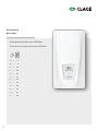 1
1
-
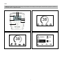 2
2
-
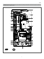 3
3
-
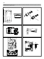 4
4
-
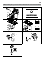 5
5
-
 6
6
-
 7
7
-
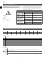 8
8
-
 9
9
-
 10
10
-
 11
11
-
 12
12
-
 13
13
-
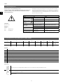 14
14
-
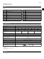 15
15
-
 16
16
-
 17
17
-
 18
18
-
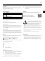 19
19
-
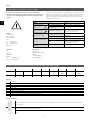 20
20
-
 21
21
-
 22
22
-
 23
23
-
 24
24
-
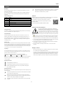 25
25
-
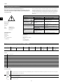 26
26
-
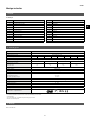 27
27
-
 28
28
-
 29
29
-
 30
30
-
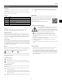 31
31
-
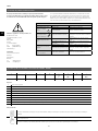 32
32
-
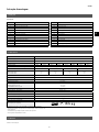 33
33
-
 34
34
-
 35
35
-
 36
36
-
 37
37
-
 38
38
-
 39
39
-
 40
40
-
 41
41
-
 42
42
-
 43
43
-
 44
44
-
 45
45
-
 46
46
-
 47
47
-
 48
48
-
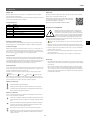 49
49
-
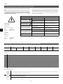 50
50
-
 51
51
-
 52
52
-
 53
53
-
 54
54
-
 55
55
-
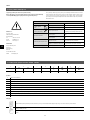 56
56
-
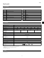 57
57
-
 58
58
-
 59
59
-
 60
60
-
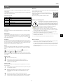 61
61
-
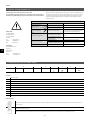 62
62
-
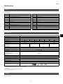 63
63
-
 64
64
-
 65
65
-
 66
66
-
 67
67
-
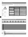 68
68
-
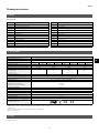 69
69
-
 70
70
-
 71
71
-
 72
72
-
 73
73
-
 74
74
-
 75
75
-
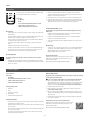 76
76
-
 77
77
-
 78
78
-
 79
79
-
 80
80


clage E-convenience Instant Water Heater DEX Next instrukcja
- Typ
- instrukcja
w innych językach
- español: clage E-convenience Instant Water Heater DEX Next Guía del usuario
- slovenčina: clage E-convenience Instant Water Heater DEX Next Užívateľská príručka
- português: clage E-convenience Instant Water Heater DEX Next Guia de usuario
- français: clage E-convenience Instant Water Heater DEX Next Mode d'emploi
Powiązane artykuły
-
clage DEX Next instrukcja
-
-
clage DEX 12 Next E-convenience Instant Water Heater Instrukcja obsługi
-
-
-
-
-
-
clage CEX 9-U E-Compact Instant Water Heater Instrukcja obsługi
-

