CalAmp DIN Rail Mount Skrócona instrukcja obsługi
- Kategoria
- Elektryczne płytki ścienne
- Typ
- Skrócona instrukcja obsługi

299 Johnson Avenue, Suite 110, Waseca, MN 56093
Tel 507-833-8819 Fax 507-833-6748
www.calamp.com
© 2012 CalAmp
March 2012
PN: 004-0000-001 Rev 5
DIN Mount Installation Instructions
Kit Number
Product
Package Contents
250-5099-005
Viper, HiPR-900, Phantom II
Mounting plate w/ spring, 8 screws, 4 lock washers, 4 nuts
250-5800-408
Integra
Mounting plate w/ spring, 4 screws
250-5800-406
T-96SR, DL-3400, SPC or DL-3282
Mounting plate w/ spring, 4 screws
250-5800-410
Vanguard SC/3000
Mounting plate w/ spring, 4 screws, 4 lock washers
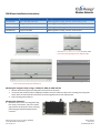
Four screw hole locations for Integra
--- Four screw-hole locations for T-96SR and DL-3400
--- Four screw-hole locations for DL-3282 and SPC
--- Four screw-hole locations for Viper and HiPR-900 Four screw-hole locations for Vanguard
--- Four screw-hole locations for Phantom II
Mounting the Vanguard, Viper, Integra, T-96SR, DL-3400, DL-3282 and SPC
1. Remove and discard original mounting plate and screws from the device.
2. Use screws (and toothed washers if supplied) included in this kit to attach the radio to the mounting plate using holes
shown above. Screws should be inserted into the mounting plate from the side with DIN clips.
3. Snap mounting plate to DIN rail.
Mounting the Phantom II
1. Mount the device to the mounting plate using
four screws, lock washers, and nuts as shown
right. Position the spring wire of the mounting
plate facing the Phantom II RS232 antenna
connector.
-
 1
1

CalAmp DIN Rail Mount Skrócona instrukcja obsługi
- Kategoria
- Elektryczne płytki ścienne
- Typ
- Skrócona instrukcja obsługi
w innych językach
Inne dokumenty
-
Yamaha DTX582K Instrukcja obsługi
-
-
-
-
-
-
Lincoln Electric IDEALARC SP-200 Instrukcja obsługi
-
-
-