
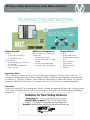
W Series Wine Rack Frame with Elbow Bracket
Installation guide for the standard W Series Frame with FCF-ELBOW
Elbow Standoff:
Included:
• (2) W Series Frame Elbow
• (2) Self-drilling Screws
Sold separately:
• W Series Bridge (cut from Frame
or Purchased)
• W Series Frame Hidden Base
Plates (optional)
Important Note:
These installation instructions will assist you with installing the VintageView W Series Frame System (10’, 12’,
or magnum congurations) using an Elbow Standoff Assembly in a oor-to-wall conguration, at an offset from
the wall up to 1’ (305mm). The Elbow is also suitable for wall-to-ceiling or wall-to-wall mounting. Visit go.vinta-
geview.com/offthewall for limitations. *See specic notes for W Series Frame 12 installation throughout*
Fasteners:
Fasteners for securing W Series racking to the Frame is included, but hardware for oor, wall, or ceiling surfaces
is not. When installing nished W Series Frame to the oor or wall, please use the following recommendations
for fasteners:
Additional Components:
(sold separately unless purchasing
complete kit)
• W Series Wine Racks
• W Series Frame (HD, 12, Mag
models)
• W Series Frame Backer Bar
(optional, single-sided displays)
Required Tools:
• Drill
• Phillips head drill bit
• Phillips head screwdriver
• Level
• Pencil or Marker
• Tape measure
• Metal cutting saw
• Metal le

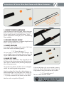
Instructions: W Series Wine Rack Frame with Elbow Extension
Figure A
Figure B
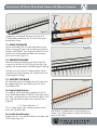
1. IDENTIFY PROPER HARDWARE
Using the chart on the previous page, identify the proper
oor/wall hardware (not included) that will be needed
for your specic project. For drywall surfaces, Vinta-
geView recommends installing to joists or wood backing
when available.
2. MEASURE CEILING HEIGHT
Measure the desired location’s installation height from the
oor to mounting location on the wall.
3. INSERT COUPLERS
Insert two (2) Frame Couplers to the section of the Frame
that will be used for the Bottom (Figure A).
** 12’ Frame Adjustment **
W Series Frame 12’ comes with welded c-channels. Con-
nect the Middle Frame to the bottom Frame be rmly slid-
ing the welded c-channel of the Middle into the bottom.
4. MARK CUT LINES
Lay each section, interlaced, as show (Figure B). Position
the Frame so that the measurement from the Top Section
(open end) to its bottom section (Mounting Plate) equals
your ceiling measurement.
The top Mounting Bracket should be on the overlapped
side for the measuring and cutting purposes.
Note the overlap of the Frame (the side that features a
hollowed opening) at the widest part of the Coupler (W
Series Frame 10’) or c-channel (W Series 12’). Subtract
1.5” (39mm) to account for the thickness of the Elbow.
Mark the cutline using a Pencil (Figure C).
If the cut mark aligns with a cross member, measure
and cut 2in (51mm) off the bottom Section (Figure D)
using a Metal Cutting Saw and start the step over.
** 12’ Frame Adjustment **
Do not cut from the center section.
Figure C
Figure D

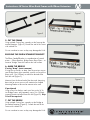
Instructions: W Series Wine Rack Frame with Elbow Extension
5. CUT THE FRAME
Using a Metal Cutting Saw, squarely cut the frame at the
marked locations (Figure E). Smooth the end of the Frame
with a Metal File.
Do not use abrasive saws as they may damage the finish.
BUILDING THE ELBOW STANDOFF BRACKET
The Elbow Standoff Bracket is a combination of several
pieces — Elbow Brackets, Bridge Frame, Base Plate — to
create a “bridge” from the Frame to the wall surface.
6. MARK THE BRIDGE
If using “drop” (most common)
If using the cut section, or drop, from the previous step as
your Bridge Frame (most common), mark a cut line on the
drop, up to 12in (305mm), to match the desired offset
from the wall (Figure F).
Measure from the closed end of the tube steel (mounting
base side) to ensure your cut will maintain the welded
Mounting Bracket to be used to connect to the wall.
If purchased
Using a Pencil or Marker, mark a cut line on the W Se-
ries Bridge Frame, sold separately, up to 12in (305mm),
to match the desired offset from the wall (Figure G). Step
10 will be required.
7. CUT THE BRIDGE
Using a Metal Cutting Saw, squarely cut the Bridge at
the marked locations (Figure H). Smooth the end of the
Frame with a Metal File.
Do not use abrasive saws as they may damage the finish.
Figure G
Figure H
Figure F
Figure E

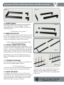
Instructions: W Series Wine Rack Frame with Elbow Extension
8. INSERT ELBOWS
Insert two (2) Elbows into the open ends of the Bridge.
Drill through the top side of the Bridge and Elbow
connection (Figure I). Attach the Elbows using two (2)
Self-Drilling Screws.
** Optional Step if using “drop”**
9. REMOVE BASE PLATE
It is common to create a more minimalist look when using
the cut section, drop, from Step 6. To achieve this look,
remove the welded Base Plate (Figure J) with a Metal Cut-
ting Saw and smooth any edges with a metal le.
** Required Adjustment if Using Purchased Bridge
or if you completed Step 9**
10. INSTALL HIDDEN BASE PLATES
If using purchased Bridge Frame instead of drop — or if
you have removed the welded Base Plate in the optional
Step 9 — insert two (2) Hidden Base Plates into the open
ends (Figure K), making sure they are oriented with the
overlap of the base sticking out to the sides of the Bridge.
Drill through the top side of the Bridge and secure the
Elbows to the Bridge Frame using two (2) Self-Drilling
Screws)
11. CONNECT THE FRAME
Connect the top Section to the Bottom, ensuring the Cou-
plers are rmly lodged together (Figure L).
** 12’ Frame Adjustment **
Connect the top Section to the connected Middle/Bottom
section by sliding c-channel into open end of Frame.
12. BUILD THE RACKS
It is common to use one (1), two (2), or (3) W Series
Wine Racks on one or both sides of a W Series Frame. If
using more than one, connect the W Series Wine Rack-
ing by removing the two (2) Endcaps from the end of
each Wine Rack where they will connect.
Figure M
Figure JFigure I
Figure K
Figure M
Figure L
Connect the Neck Strips (smaller bottle impressions)
together with the supplied Wine Rack Couplers
(Figure M). Repeat with the Base Strips (larger bottle
impressions).
Figure M

Instructions: W Series Wine Rack Frame with Elbow Extension
VintageView recommends leaving a minimum of 6”
(153mm) above and below the W Series Racks when
assembled to Frame.
13. PLACE THE RACKS
Lay the connected Strips in the desired location on the
Frame, ensuring the Neck Strips are facing in preferred
direction. IMPORTANT: One single Wine Rack Strip must
extend 12in (305mm) above or below all connection
points of the Frame (Figure O).
14. SECURE THE RACKS
Attach the Racking Assembly to the Frame (Figure N)
using two (2) or three (3) Self Drilling Screws per Strip
(quantity will vary based on individual height of racking).
Then press two (2) or three (3) Mounting Hole Covers
into each Strip section (quantity will vary based on indi-
vidual height of racking).
15. SUPPORT THE BACK
All connection points on the backside of the Frame must
be supported by either Wine Racking or a W Series
Frame Backer Bar.
For Single-Sided Displays
Use eight (8) Self-Drilling Screws to attach two (2) W
Series Frame Backer Bars (FCF-BACK) to the back side of
the Frame, centered over the two connection points. Then
press eight (8) Mounting Hole Covers over the Screws
(Figure P).
** 12’ Frame Adjustment **
The 12’ frame features four connection points and re-
quires four (4) Backer Bars.
For Double-Sided Displays
Repeat Steps 9-11 to install Wine Racks to the back side
of the Frame (Figure Q).
Figure N
Figure P
IMPORTANT: The Backer Bar or Wine Racking must
extend 12in (305mm) above or below all connection
points of the Frame.
Figure O
Figure Q

Instructions: W Series Wine Rack Frame with Elbow Extension
Figure R
Figure O
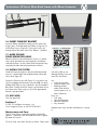
16. INSERT STANDOFF BRACKET
Insert the Elbow Standoff Assembly into the open end
of the Frame. Drill and attach the Elbows using two (2)
Self-Drilling Screws (Figure R). Ensure the Screws go
through one of the three sides of the Elbows’ c-channel.
17. MARK CEILING/
FLOOR MOUNTING HOLES
Place the Frame in desired location. Ensure it is plumb
with a level and mark the mounting holes on both the
wall and the oor. Set the Frame aside and pre-drill any
required pilot holes based on hardware selection.
18. INSTALL THE SYSTEM
Stand the Frame Assembly in the desired location and
ensure it is plumb both front and back and side-to-side
with a level (Figure R).
Secure the Frame to the wall (Figure S) using either two
(2) of the appropriate fasteners (not provided) into each
Hidden Base Plate or two (2) fasteners into the standard
Base Plate. Double check the Frame is plumb and secure
the Frame to the oor using two (2) of the appropriate
fasteners (not provided).
19. ADD WINE
Only the good stuff.
Problems?
Try BILT 3D intelligent instructions, visit
www.vintageview.com, or call 303-504-9463.
Maintenance and Care:
The W Series Frame should be regularly checked for
tightness. Should any rack be found to be loose, tighten
by hand until secure.
W Series steel wine racks are easy to clean. Simply wipe
with a dry cloth or use
rubbing alcohol. Here are
more Dos and Don’ts….
Use
• A dry dusting cloth
• Compressed air cans
• Rubbing alcohol
and a clean cloth to
remove grease, oil, or
other substances
Don’t use:
• Dish soap
• Household cleaners
• Abrasive materials
• Any chemical
Improper care may void the manufacturer’s warran-
ty.
-
 1
1
-
 2
2
-
 3
3
-
 4
4
-
 5
5
-
 6
6


VintageView W Series Wine Rack Frame Elbow Standoff Bracket Kit Instrukcja instalacji
- Typ
- Instrukcja instalacji
- Niniejsza instrukcja jest również odpowiednia dla
w innych językach
Powiązane artykuły


Inne dokumenty
-
Sea Ray 2005 420DA Parts Manual
-
-
-
Amana MVH240W Instrukcja obsługi
-
Yamaha R2 Instrukcja obsługi
-
-
-
-