
USER'S MANUAL/HANDBUCH/MANUEL DE L'UTILISATEUR
/MANUAL DEL USUARIO/MANUALE UTENTE/INSTRUKCJA OBSŁUGI
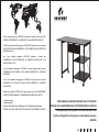
Folding Working Table/Klappbarer Schreibtisch/Bureau Pliant
/Escritorio Plegable/Tavolo Pieghevole con Ruote/Biurko składane
HW67486
UNITED STATES
CANADA UNITED KINGDOM
GERMANY
FRANCE
ITALY
SPAIN
JAPAN
RUSSIA
AUSTRALIA
EN DE FR ES IT PL
With your inspiring rating, COSTWAY will be more consistent to offer you EASY
SHOPPING EXPERIENCE, GOOD PRODUCTS and EFFICIENT SERVICE!
Mit Ihrer inspirierenden Bewertung wird COSTWAY konsistenter sein, um Ihnen
EIN SCHÖNES EINKAUFSERLEBNIS, GUTE PRODUKTE und EFFIZIENTEN
SERVICE zu bieten!
Avec votre évaluation inspirante, COSTWAY continuera à fournir une
EXPÉRIENCE D’ACHAT PRATIQUE, des PRODUITS DE QUALITÉ et un
SERVICE EFFICACE !
Con su calificación inspiradora, COSTWAY será más consistente para ofrecerle
EXPERIENCIA DE COMPRA FÁCIL, BUENOS PRODUCTOS y SERVICIO
EFICIENTE.
Con la tua valutazione incoraggiante, COSTWAY sarà più coerente per offrirti
ESPERIENZA DI ACQUISTO FACILE, BUONI PRODOTTI e SERVIZIO
EFFICIENTE!
Dzięki twojej opinii COSTWAY będzie mógł oferować jeszcze WYGODNIEJSZE
ZAKUPY, LEPSZE PRODUKTY i SPRAWNIEJSZĄ OBSŁUGĘ KLIENTA.
US office: Fontana
UK office: Ipswich
DE office: FDS GmbH, Neuer Höltigbaum 36, 22143 Hamburg, Deutschland
FR office : 26 RUE DU VERTUQUET, 59960 NEUVILLE EN FERRAIN, FRANCE

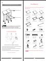
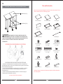
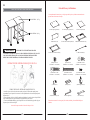
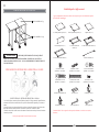
Parts and Hardware List
Please read completely through the instructions and verify that all listed parts and hardware are present
before beginning assembly.
Tools required: Hex wrench and open wrench (provided) and Phillips screwdriver (not provided).
A- Large Top Panel (Qty. 1) B- Small Top Panel (Qty. 1) C- Fixed Shelf (Qty. 2)
D- Back Panel (Qty. 1) E- Left End Frame (Qty. 1) F- Middle End Frame (Qty. 1)
G- Right End Frame (Qty. 1) H- Metal Bar (Qty. 2)
(1) Cam Lock (Qty. 8+1 extra) (2) Cam Bolt (Qty. 8+1 extra) (3) M6 x 12 mm Bolt (Qty. 4+1 extra)
(4) M6 x 25 mm Bolt
(5) M6 x 50 mm Bolt (6) M4 x 15 mm Screw
(Qty. 2+1 extra) (Qty. 4+1 extra) (Qty. 18+1 extra)
(7) Locator Pin (Qty. 1) (8) Butt Hinge (Qty. 2) (9) Swivel Caster (Qty. 3)
(10) Locking Caster (Qty. 3) Hex Wrench (Qty. 1) Open Wrench (Qty. 1)
CAM LOCK SYSTEM OPERATION
HOW THE KNOCK DOWN (KD) ASSEMBLY SYSTEM WORKS
You are now ready to assemble the KD unit.
M A X I M U M R E C O M M E NDE D W E I G H T LO A D S
THIS UNIT IS INTENDED FOR USE ONLY WITH THE MAXIMUM
WEIGHTS INDICATED. USE WITH LOAD HEAVIER THAN THE MAXIMUM
WEIGHTS INDICATED MAY RESULT IN INSTABILITY, CAUSING POSSIBLE INJURY.
MAXIMUM LOAD 200 lb. (90.7 kg)
MAXIMUM LOAD 50 lb. (22.6 kg)
1. Screw the cam bolt into the threaded inserts on the panel. Connect both panels together; making sure
cam bolt goes into the pre-drilled hole on the end of panel for cam lock.
2. Insert the cam lock into the pre-drilled large hole on the panel. Make sure the arrow on the face of
cam lock faces out and points towards cam bolt.
3. Take a Phillips screwdriver and rotate the cam lock clockwise to lock the cam bolt in place.
EN
02 03

Assembly Instructions
6
6
7
A
B
8
8
A
B
F
G
F/G
5
B
Assembly Instructions
2
F/G
G
F
F
F
G
C
C
C
F/G
1
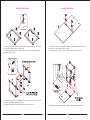
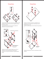
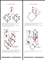
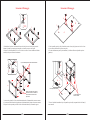
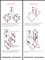
1. Unpack the unit and confirm that you have all the hardware and required parts. Assemble the unit on
a carpeted floor or the empty carton to avoid any scratch.
2. Lay out the End Frames (F and G) with the holes facing up. Securely screw the Cam Bolts (2) into
the threaded sockets as shown.
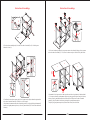
5. Combine the Top Panels (A and B) together by attaching two Butt Hinges (8) at the joint with six 15
mm Screws (6) per hinge, using the pilot holes as a guide.
6. Securely screw one Locator Pin (7) into the threaded insert on the Large Top Panel (A).
7. Attach the assembled pedestal to the Small Top Panel (B) with four 50 mm Bolts (5) as shown.
3. Attach two Fixed Shelves (C) to the Middle End Frame (F) by engaging two Cam Locks (1) in each
(Refer to the Cam Lock system operation suppl ement).
4. Repeat the same procedure to attach the Right End Frame (G) at the opposite end.
04 05

Assembly Instructions
2
3
1
A
B
E
B
A
E
7
E
F
E
G
9
9
9
10
10
10
9/10
E/F/G
Assembly Instructions
A
F
D
E
E
7
D
E
4
4
FD
6
6
A
B
F
G
H
F/G
H
3
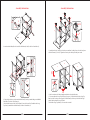
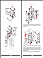
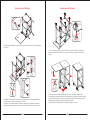
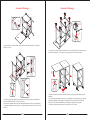
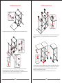
9. Using the pilot holes as a guide, attach the Back Panel (D) to the pre-attached hinges on the Middle
End Frame (F) with six 15 mm Screws (6).
10. Position the front post of the Left End Frame (E) onto the Locator Pin (7) installed on the Large
Top Panel (A) and attach to the Back Panel (D) with two 25 mm Bolts (4).
12. Ask for assistance to lift the unit upright and position at the desired location.
13. You can collapse the Large Top Panel (A) to save space. To fold the desk, lift up the Large Top
Panel (A) a little so that you can swing the Left End Frame (E) all the way to the front of the right
pedestal, then lay down the Large Top Panel.
14. Extend the Large Top Panel (A) in reverse order as needed.
11. Attach three Swivel Casters (9) to the front posts and three Locking Casters (10) to the back posts
of the End Frames (E, F and G). Tighent the casters in place with the provided open wrench.
8. Attach two Metal Bars (H) to the back of the End Frames (F and G) with four 12 mm Bolts (3).
06 07

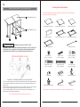
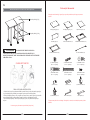
Teile- und Hardwareliste
A- Große obere Platte x1 B- Kleine obere Platte x1 C- Festes Regal x2
D- Rückseite x1 E- Linker Endrahmen x1 F- Mittlerer Endrahmen x1
(1) Nockenverriegelung
(x8+ 1 Ersatz)
(2) Nockenschraube
(x 8 + 1 Ersatz)
(3) Schraube M6 x 12 mm
(x 4 + 1 Ersatz)
(4) Schraube M6 x 25 mm
(x 2 + 1 Ersatz)
(5) Schraube M6 x 50 mm
(x 4 + 1 Ersatz)
(6) Schraube M4 x 15 mm
(x 18 + 1 Ersatz)
(7) Positionierungsstift (x 1) (8) Kolbenscharnier (x 2) (9) Lenkrolle (x 3)
(10) Rolle mit Schloss (x 3) Inbusschlüssel (x 1) Gabelschlüssel (x 1)
G- Rahmen am rechten Ende x1 H-Metallstange x2
BETRIEB DES NOCKENVERRIEGELUNGSSYSTEMS
FUNKTIONSWEISE DES KNOCK-DOWN-MONTAGESYSTEMS (KD)
Jetzt können Sie die KD-Einheit zusammenbauen.
MAXIMAL EMPFOHLENE GEWICHTSBELASTUNG
WARNUNG
DIESES PRODUKT IST NUR ZUR VERWENDUNG MIT DEN
ANGEGEBENEN MAXIMALGEWICHTEN VORGESEHEN. DIE VERWENDUNG MIT
EINER LAST, DIE SCHWERER ALS DIE ANGEGEBENEN MAXIMALGEWICHTE IST,
KANN ZU INSTABILITÄT FÜHREN UND MÖGLICHE VERLETZUNGEN
VERURSACHEN.
maximale Belastung 90,7 kg
maximale Belastung 22,6 kg
1. Schrauben Sie die Nockenschraube in die Gewindeeinsätze an der Platte. Verbinden Sie beide
Panels miteinander. Stellen Sie sicher, dass die Nockenschraube in das vorgebohrte Loch am Ende der
Platte für die Nockenverriegelung passt.
2. Setzen Sie die Nockenverriegelung in das vorgebohrte große Loch in der Platte ein. Stellen Sie
sicher, dass der Pfeil auf der Vorderseite der Nockenverriegelung nach außen zeigt und zur
Nockenschraube zeigt.
3. Nehmen Sie einen Kreuzschlitzschraubendreher und drehen Sie die Nockenverriegelung im
Uhrzeigersinn, um die Nockenschraube zu arretieren.
Bitte lesen Sie die Anweisungen vollständig durch und stellen Sie sicher, dass alle aufgelisteten Teile und
Hardware vorhanden sind, bevor Sie mit der Montage beginnen.
Erforderliche Werkzeuge: Inbusschlüssel und Gabelschlüssel (mitgeliefert) und Kreuzschlitzschrauben-
dreher (nicht mitgeliefert).
DE
08 09

Montageanleitungen
6
6
7
A
B
8
8
A
B
F
G
F/G
5
B
Positionierstift
die Gewindebuchsen
für Metallstange
Montageanleitungen
2
F/G
G
F
F
F
G
C
C
C
F/G
1
Gewindehülsen zeigen in die gleiche Richtung
Die Nockenschlösser zeigen zum
Boden, wenn das Produkt
aufrecht gedreht wird.
1. Packen Sie das Produkt aus und vergewissern Sie sich, dass Sie über die gesamte Hardware und die
erforderlichen Teile verfügen. Montieren Sie das Gerät auf einem Teppichboden oder dem leeren
Karton, um Kratzer zu vermeiden.
2. Legen Sie die Endrahmen (F und G) mit den Löchern nach oben aus. Schrauben Sie die
Nockenschrauben (2) wie gezeigt fest in die Gewindebuchsen.
5. Kombinieren Sie die Tischplatten (A und B), indem Sie zwei Stoßscharniere (8) an der
Verbindungsstelle mit sechs 15-mm-Schrauben (6) pro Scharnier anbringen, wobei Sie die
Führungslöcher als Führung verwenden.
6. Schrauben Sie einen Positionierungsstift (7) fest in den Gewindeeinsatz auf der großen Oberseite
(A).
7. Befestigen Sie den montierten Sockel wie gezeigt mit vier 50-mm-Schrauben (5) an der kleinen
oberen Platte (B).
3. Befestigen Sie zwei feste Regale (C) am mittleren Endrahmen (F), indem Sie jeweils zwei
Nockenschlösser (1) einrasten (siehe Betriebsergänzung zum Nockenschlosssystem).
4. Wiederholen Sie den Vorgang, um den rechten Endrahmen (G) am gegenüberliegenden Ende
anzubringen.
10 11

Montageanleitungen
2
3
1
A
B
E
B
A
E
7
E
F
E
G
9
9
9
10
10
10
9/10
E/F/G
Montageanleitungen
A
F
D
E
E
7
D
E
4
4
FD
6
6
A
B
F
G
H
F/G
H
3
9. Befestigen Sie die Rückwand (D) anhand der Führungslöcher mit sechs 15-mm-Schrauben (6) an
den vormontierten Scharnieren am mittleren Endrahmen (F).
10. Positionieren Sie den vorderen Pfosten des linken Endrahmens (E) auf dem Positionierungsstift (7),
der an der großen oberen Platte (A) angebracht ist, und befestigen Sie ihn mit zwei 25-mm-Schrauben
(4) an der hinteren Platte (D).
12. Bitten Sie um Unterstützung, um das Gerät aufrecht anzuheben und an der gewünschten Stelle zu
positionieren.
13. Sie können das große obere Bedienfeld (A) reduzieren, um Platz zu sparen. Um den Schreibtisch
zusammenzuklappen, heben Sie die große obere Abdeckung (A) ein wenig an, damit Sie den linken
Endrahmen (E) ganz nach vorne auf den rechten Sockel schwenken können, und legen Sie dann die
große obere Abdeckung ab.
14. Ziehen Sie das große obere Bedienfeld (A) nach Bedarf in umgekehrter Reihenfolge heraus.
11. Befestigen Sie drei Lenkrollen (9) an den vorderen Pfosten und drei Verriegelungsrollen (10) an
den hinteren Pfosten der Endrahmen (E, F und G). Ziehen Sie die Rollen mit dem mitgelieferten
Gabelschlüssel fest.
8. Befestigen Sie zwei Metallstangen (H) mit vier 12-mm-Schrauben (3) an der Rückseite der
Endrahmen (F und G).
12 13

Liste des pièces et du matériel
A- Grand panneau supérieur (x 1) B- Petit panneau supérieur (x 1) C-Tablette de fixation (x 2)
D- Panneau arrière (x 1) E- Cadre d’extrémité gauche (x 1) F- Cadre d’extrémité centrale (x 1)
(1) Serrure à came
(Qté. 8+1 de rechange)
(2) Boulon à came
(Qté. 8+1 de rechange)
(3) M6 x 12 mm Boulon
(Qté. 4+1 de rechange)
(4) Boulon M6 x 25 mm
(Qté. 2+1 de rechange)
(5) Boulon M6 x 50 mm
(Qté. 4+1 de rechange)
(6) Vis M4 x 15 mm
(Qté. 18+1 de rechange)
(7) Goupille (x1) (8) Charnière (x2) (9) Roulette pivotante (x3)
(10) Roulette de verrouillage (x3) Clé hexagonale (x1) Clé plate (x1)
G- Cadre d’extrémité droit (x 1) H- Barre centrale (x 2)
SYSTÈME DE SERRURE À CAME
COMMENT LE SYSTÈME DE SERRURE À CAME FONCTIONNE
Vous êtes maintenant prêt à assembler le système de serrure à came
CHARGES MAXIMALES RECOMMANDÉES
AVERTISSEMENT
CE PRODUIT EST DESTINÉ À ÊTRE UTILISÉ
UNIQUEMENT AVEC LES CHARGES MAXIMALES INDIQUÉES. L’UTILISATION AVEC
UNE CHARGE PLUS LOURDE QUE LES CHARGES MAXIMALES INDIQUÉES PEUT
ENTRAÎNER UNE INSTABILITÉ, CAUSANT DES BLESSURES ÉVENTUELLES.
CHARGE MAXIMALE 90,7 kg
CHARGE MAXIMALE 22,6 kg
1. Vissez le boulon à came dans les inserts filetés du panneau. Raccordez les deux panneaux ensemble
en vous assurant que le boulon à came entre dans le trou pré-percé à l’extrémité du panneau pour la
serrure à came.
2. Insérez la serrure à came dans le grand trou pré-percé sur le panneau. Assurez-vous que la flèche sur
la face de la serrure à came est orientée vers l’extérieur et pointe vers le boulon à came.
3. Prenez un tournevis Phillips et faites tourner la serrure à came dans le sens des aiguilles d’une
montre pour verrouiller le boulon à came en place.
Veuillez lire attentivement les instructions et vérifier que toutes les pièces et le matériel indiqués sont
présents avant de commencer l’assemblage.
Outils nécessaires : Clé hexagonale et clé plate (fournies) et tournevis cruciforme (non fournis).
FR
14 15

Instructions d’assemblage
6
6
7
A
B
8
8
A
B
F
G
F/G
5
B
Goupille de localisation
Les douilles filetées pour
barre métallique
Instructions d’assemblage
2
F/G
G
F
F
F
G
C
C
C
F/G
1
Les douilles filetées pointent dans la même direction
Les serrures à cames sont
orientées vers le sol lorsque
l’unité est tournée vers le haut
1. Déballez le produit et confirmez que vous avez tout le matériel et les pièces nécessaires. Assemblez
le produit sur un sol moquetté ou sur le carton vide pour éviter toute rayure.
2. Disposez les cadres d’extrémité (F et G) avec les trous vers le haut. Vissez fermement les boulons à
came (2) dans les douilles filetées comme indiqué.
5. Combinez les panneaux supérieurs (A et B) ensemble en fixant deux charnières (8) à l’articulation
avec six vis (6) de 15 mm pour chaque charnière, en utilisant les trous pilotes comme guide.
6. Vissez fermement une goupille de positionnement (7) dans l’insert fileté du grand panneau supérieur
(A).
7. Fixez la base assemblée au petit panneau supérieur (B) à l’aide de quatre boulons de 50 mm (5)
comme indiqué.
3. Fixez deux tablettes de fixation (C) au cadre d’extrémité central (F) en engageant deux serrures à
came (1) dans chacun d’eux (voir le supplément sur le fonctionnement du système de serrures à came).
4. Répétez la même procédure pour fixer le cadre d’extrémité droit (G) à l’extrémité opposée.
16 17

Instructions d’assemblage
2
3
1
A
B
E
B
A
E
7
E
F
E
G
9
9
9
10
10
10
9/10
E/F/G
Instructions d’assemblage
A
F
D
E
E
7
D
E
4
4
FD
6
6
A
B
F
G
H
F/G
H
3
9. En utilisant les trous pilotes comme guide, fixez le panneau arrière (D) aux charnières pré-attachées
sur le cadre d’extrémité central (F) à l’aide de six vis de 15 mm (6).
10. Positionnez le montant avant du cadre d’extrémité gauche (E) sur la goupille de positionnement (7)
installée sur le grand panneau supérieur (A) et fixez le panneau arrière (D) à l’aide de deux boulons de
25 mm (4).
2. Demandez de l’aide pour soulever l’unité en position verticale et la positionner à l’endroit souhaité.
13. Vous pouvez rabattre le grand panneau supérieur (A) pour gagner de la place. Pour plier le bureau,
soulevez un peu le grand panneau supérieur (A) afin de pouvoir faire pivoter le cadre d’extrémité
gauche (E) jusqu’à l’avant de la base droite, puis déposez le grand panneau supérieur.
14. Déployez le grand panneau supérieur (A) dans l’ordre inverse, selon les besoins.
11. Fixez trois roulettes pivotantes (9) aux poteaux avant et trois roulettes de blocage (10) aux poteaux
arrière des cadres d’extrémité (E, F et G). Serrez les roulettes en place à l’aide de la clé plate fournie.
8. Fixez deux barres métalliques (H) à l’arrière des cadres d’extrémité (F et G) à l’aide de quatre
boulons de 12 mm (3).
18 19

Lista de Piezas y de Hardware
A- Panel superior grande (x1) B- Panel superior pequeño (x1) C- Estante de fijación (x2)
D- Panel trasero (x1) E- Marco del extremo izquierdo (x1) F- Marco del extremo medio (x1)
(1) Bloqueo de leva
(Cantidad 8 + 1 de recambio)
(2) Perno de leva
(Cantidad 8 + 1 de recambio)
(3) Perno M6 x 12 mm
(Cantidad 4 + 1 de recambio)
(4) Perno M6 x 25 mm
(Cantidad 2 + 1 de recambio)
(5) Perno M6 x 50 mm
(Cantidad 4 + 1 de recambio)
(6) Tornillo M4 x 15 mm
(Cantidad 18 + 1 de recambio)
(7) Pasador (x1) (8) Bisagra (x2) (9) Rueda giratoria (x3)
(10) Rueda de bloqueo (x3) Llave hexagonal (x1) Llave abierta (x1)
G- Marco del extremo derecho (x1) H- Barra de metal (x2)
OPERACIÓN DEL SISTEMA DE BLOQUEO DE LEVA
CÓMO FUNCIONA EL SISTEMA DE BLOQUEO DE LEVA
Ahora está listo para ensamblar el sistema de bloqueo de leva
CARGAS MÁXIMAS RECOMENDADAS
ADVERTENCIA
ESTE PRODUCTO ESTÁ DISEÑADO PARA SER
UTILIZADO ÚNICAMENTE CON LAS CARGAS MÁXIMAS INDICADAS. EL USO CON
UNA CARGA MÁS PESADA QUE LAS CARGAS MÁXIMAS INDICADAS PUEDE
RESULTAR EN INESTABILIDAD, CAUSANDO POSIBLES LESIONES.
CARGA MÁXIMA90,7 kg
CARGA MÁXIMA: 22,6 kg
1. Atornille el perno de leva en los insertos roscados en el panel. Conecte ambos paneles juntos
asegurándose de que el perno de leva entre en el orificio pretaladrado en el extremo del panel para el
bloqueo de leva.
2. Inserte el bloqueo de leva en el orificio grande pretaladrado en el panel. Asegúrese de que la flecha
en la cara del bloqueo de leva mire hacia afuera y apunte hacia el perno de leva.
3. Tome un destornillador Phillips y gire el bloqueo de leva en el sentido de las agujas del reloj para
bloquear el perno de leva en su lugar.
Lea completamente las instrucciones y verifique que todas las piezas y el hardware enumerados estén
presentes antes de comenzar el montaje.
Herramientas necesarias: llave hexagonal y llave abierta (incluidas) y destornillador Phillips (no
incluido).
ES
20 21

Instrucciones del Montaje
6
6
7
A
B
8
8
A
B
F
G
F/G
5
B
Pasador de localizador
Los encajes roscados
para barra de metal.
Instrucciones del Montaje
2
F/G
G
F
F
F
G
C
C
C
F/G
1
Los encajes roscados apuntan en la misma dirección.
Los bloqueos de leva mirarán
hacia el piso cuando la unidad
esté en posición vertical.
1. Desembale el producto y confirme que tiene todo el hardware y las piezas necesarias. Monte el
producto en un piso alfombrado o en la caja vacía para evitar rayones.
2. Disponga los marcos del extremo (F y G) con los orificios hacia arriba. Atornille firmemente los
pernos de leva (2) en los encajes roscados como se muestra.
5. Combine los paneles superiores (A y B) juntos fijando dos bisagras (8) a la junta con seis tornillos
de 15 mm (6) para cada bisagra, utilizando los orificios guía como guía.
6. Atornille firmemente un pasador de localizador (7) en el inserto roscado en el panel superior grande
(A).
7. Fije la base ensamblada al panel superior pequeño (B) con cuatro pernos de 50 mm (5) como se
muestra.
3. Fije dos estantes de fijación (C) al marco del extremo intermedio (F) enganchando dos bloqueos de
leva (1) en cada uno (Consulte el suplemento de operación del sistema de bloqueo de leva).
4. Repita el mismo procedimiento para fijar el marco del extremo derecho (G) en el extremo opuesto.
22 23

Instrucciones del Montaje
2
3
1
A
B
E
B
A
E
7
E
F
E
G
9
9
9
10
10
10
9/10
E/F/G
Instrucciones del Montaje
A
F
D
E
E
7
D
E
4
4
FD
6
6
A
B
F
G
H
F/G
H
3
9. Utilizando los orificios guía como guía, fije el panel posterior (D) a las bisagras preinstaladas en el
marco del extremo medio (F) con seis tornillos de 15 mm (6).
10. Coloque el poste delantero del marco del extremo izquierdo (E) en el pasador de localizador (7)
instalado en el panel superior grande (A) y fíjelo al panel trasero (D) con dos pernos de 25 mm (4).
12. Solicite ayuda para levantar la unidad en posición vertical y colocarla en el lugar deseado.
13. Puede plegar el panel superior grande (A) para ahorrar espacio. Para doblar el escritorio, levante un
poco el panel superior grande (A) para que pueda girar el marco del extremo izquierdo (E) a la parte
delantera de la base derecha, luego coloque el panel superior grande.
14. Extienda el panel superior grande (A) en orden inverso según sea necesario.
11. Fije tres ruedas giratorias (9) a los postes delanteros y tres ruedas de bloqueo (10) a los postes
traseros de los marcos del extremo (E, F y G). Apriete las ruedas en su lugar con la llave abierta
provista.
8. Fije dos barras de metal (H) a la parte posterior de los marcos del extremo (F y G) con cuatro pernos
de 12 mm (3).
24 25

Lista delle parti e degli accessori
A- Grande pannello superiore (x 1) B- Piccolo pannello superiore (x 1) C- Ripiano fisso (x 2)
D- Pannello posteriore (x 1) E- Telaio dell'estremità
sinistra (x 1)
F- Telaio dell'estremità centrale (x 1)
(1) Serratura a camma
(Quantità. 8+1 di ricambio)
(2) Bullone a camma
(Quantità. 8+1 di ricambio)
(3) M6 x 12 mm Bullone
(Quantità. 4+1 di ricambio)
(4) Bullone M6 x 25 mm
(Quantità. 2+1 di ricambio)
(5) Bullone M6 x 50 mm
(Quantità. 4+1 di ricambio)
(6) Vite M4 x 15 mm
(Quantità. 18+1 di ricambio)
(7) Perno di posizionamento (x1) (8) Cerniera (x2) (9) Ruota girevole (x3)
(10) Ruota bloccabile (x3) Chiave esagonale (x1) Chiave aperta (x1)
G- Telaio dell'estremità destra (x 1) H- Barra in metallo (x 2)
OPERAZIONE DEL SISTEMA DELLA SERRATURA A CAMME
COME FUNZIONA IL SISTEMA DI SERRATURA A CAMMA
Ora sei pronto per montare il sistema di serratura a camma.
CARICHI MASSIMI CONSIGLIATI
AVVERTENZA
UTILIZZARE QUESTO PRODOTTO SOLO QUANDO È
INDICATA LA CAPACITÀ DI CARICO MASSIMA. SE SUPERA LA CAPACITÀ DI
CARICO MASSIMA SPECIFICATA, IL TAVOLO POTREBBE DIVENTARE INSTABILE E
CAUSARE LESIONI.
CARICO MASSIMO: 90,7 kg
CARICO MASSIMO: 22,6 kg
1. Avvitare il bullone a camma negli inserti filettati sul pannello. Collegare entrambi i pannelli insieme;
Assicurarsi che il bullone a camma entri nel foro preforato all'estremità del pannello per la serratura a
camma.
2. Inserire la serratura a camma nel grande foro preforato sul pannello. Assicurarsi che la freccia sulla
faccia della serratura a camma sia rivolta verso l'esterno e punti verso il bullone a camma.
3. Prendere un cacciavite a stella e ruotare la serratura a camma in senso orario per bloccare la serratura
a camma in posizione.
Leggere completamente le istruzioni e verificare che tutte le parti e gli accessori elencati siano presenti
prima di iniziare l'assemblaggio.
Strumenti richiesti: Chiave esagonale e chiave aperta (in dotazione) e cacciavite a croce (non in
dotazione).
IT
26 27

Istruzioni di Montaggio
6
6
7
A
B
8
8
A
B
F
G
F/G
5
B
Perno di posizionamento
Le prese filettate per
barra in metallo
Istruzioni di Montaggio
2
F/G
G
F
F
F
G
C
C
C
F/G
1
Le prese filettate puntano nella stessa direzione.
Quando il prodotto viene girato in
posizione verticale, le serrature a
camme saranno rivolte verso il
pavimento.
1. Disimballare il prodotto e confermare di disporre di tutti gli accessori e delle parti necessarie.
Montare il prodotto su un pavimento in moquette o sul cartone vuoto per evitare graffi.
2. Disporre i telai dell'estremità(F e G) con i fori rivolti verso l'alto. Avvitare saldamente i bulloni a
camma (2) nelle prese filettate come mostrato.
5. Unire i pannelli superiori (A e B) fissando due cerniere di testa (8) al giunto con sei viti da 15 mm
(6) per cerniera, utilizzando i fori pilota come guida.
6. Avvitare saldamente un perno di posizionamento (7) nell'inserto filettato sul pannello superiore
grande (A).
7. Fissare il piedistallo assemblato al piccolo pannello superiore (B) con quattro bulloni da 50 mm (5)
come mostrato.
3. Attaccare due ripiani fissi (C) al telaio dell'estremitàcentrale (F) innestando due serrature a camma
(1) in ciascuno (Fare riferimento al supplemento sul funzionamento del sistema di serratura a camma).
4. Ripetere la stessa procedura per fissare il telaio dell'estremità destra (G) all'estremità opposta.
28 29

Istruzioni di Montaggio
2
3
1
A
B
E
B
A
E
7
E
F
E
G
9
9
9
10
10
10
9/10
E/F/G
Istruzioni di Montaggio
A
F
D
E
E
7
D
E
4
4
FD
6
6
A
B
F
G
H
F/G
H
3
9. Usando i fori pilota come guida, fissare il pannello posteriore (D) alle cerniere preassemblate sul
telaio dell'estremità centrale (F) con sei viti da 15 mm (6).
10. Posizionare il montante anteriore del telaio dell'estremità sinistra (E) sul perno di posizionamento
(7) installato sul pannello superiore grande (A) e fissarlo al pannello posteriore (D) con due bulloni da
25 mm (4).
12. Chiedere assistenza per sollevare il prodotto in posizione verticale e posizionarlo nella posizione
desiderata.
13. Puoi piegare il grande pannello superiore (A) per risparmiare spazio. Per piegare il tavolo, sollevare
leggermente il pannello superiore grande (A) in modo da poter far oscillare il telaio dell'estremità
sinistra (E) fino in fondo al piedistallo destro, quindi adagiare il pannello superiore grande.
14. Estendere il pannello superiore grande (A) in ordine inverso, se necessario.
11. Attaccare tre ruote girevoli (9) ai montanti anteriori e tre ruote bloccabili (10) ai montanti posteriori
dei telai dell'estremità(E, F e G). Stringere le ruote in posizione con la chiave aperta fornita.
8. Attaccare due barre in metallo (H) alla parte posteriore dei telai dell'estremità(F e G) con quattro
bulloni da 12 mm (3).
30 31

Lista części i akcesoriów
A- Duży panel górny (x 1) B- Mały panel górny (x 1) C-Płytka mocująca (x 2)
D- Panel tylny (x 1) E- Lewa rama końcowa (x 1) F- Środkowa rama końcowa (x 1)
(1) Zamek krzywkowy
(szt. 8 + 1 zapasowy)
(2) Śruba mimośrodowa
(szt. 8 + 1 zapasowy)
(3) Śruba M6 x 12 mm
(szt. 4 + 1 zapasowy)
(4) Śruba M6 x 25mm
(szt. 2 + 1 zapasowy)
(5) Śruba M6 x 50 mm
(szt. 4 + 1 zapasowy)
(6) Śruba M4 x 15mm
(szt. 18 + 1 zapasowy)
(7) Sworzeń (x1) (8) Zawias (x2) (9) Obrotowe kółko (x3)
(10) Koło blokujące (x3) Klucz imbusowy (x1) Klucz płaski (x1)
G- Prawa rama końcowa (x 1) H- Listwa środkowa (x 2)
ZAMEK KRZYWKOWY
DZIAŁANIE ZAMKA KRZYWKOWEGO
Jesteś teraz gotowy do montażu systemu blokady krzywkowej.
MAKSYMALNE ZALECANE OBCIĄŻENIA
OSTRZEŻENIE
TEN PRODUKT JEST PRZEZNACZONY DO
UŻYTKOWANIA MAJĄC NA UWADZE MAKSYMALNE OBCIĄŻENIA. W
PRZECIWNYM RAZIE, MOŻE TO SPOWODOWAĆ NIESTABILNOŚĆ I PÓŹNIEJSZE
OBRAŻENIA CIAŁA.
Maksymalny udźwig:90,7 kg
Maksymalny udźwig:22,6 kg
1. Wkręcić śrubę krzywki w gwintowane wkładki w panelu. Połączyć ze sobą dwa panele, upewniając
się, że śruba krzywkowa przechodzi przez wstępnie wywiercony otwór na końcu panelu.
2. Włożyć blokadę krzywkową w duży, wstępnie wywiercony otwór w panelu. Upewnij się, że strzałka
na powierzchni blokady jest skierowana na zewnątrz i wskazuje w kierunku śruby krzywki.
3. Weź śrubokręt krzyżakowy i obróć krzywkę blokującą w prawo, aby zablokować krzywkę na
miejscu.
Przeczytaj uważnie instrukcję i sprawdź, czy wszystkie wymienione części i osprzęt są zawarte w
zestawie.
Wymagane narzędzia: klucz sześciokątny i klucz płaski (w zestawie) oraz śrubokręt krzyżakowy (brak w
zestawie).
PL
32 33

INSTRUKCJE MONTAŻU
6
6
7
A
B
8
8
A
B
F
G
F/G
5
B
Kołek ustalający
Tuleje gwintowane do
prętów metalowych
INSTRUKCJE MONTAŻU
2
F/G
G
F
F
F
G
C
C
C
F/G
1
Tuleje gwintowane ustawione są w tym samym kierunku
Zamki krzywkowe skierowane są
w stronę podłogi, gdy produkt jest
odwrócony
1. Rozpakuj produkt i upewnij się, że masz wszystkie niezbędne materiały i części. Zamontuj produkt
na podłodze pokrytej wykładziną lub na pustym kartonie, aby uniknąć zarysowania.
2. Ustawić ramy końcowe (F i G) tak, aby otwory były skierowane do góry. Wkręcić mocno śruby
mimośrodowe (2) w gwintowane tuleje, jak pokazano na rysunku.
5. Połącz górne panele (A i B) razem, mocując dwa zawiasy (8) do łączeń, za pomocą sześciu śrub 15
mm (6) dla każdego łączenia, używając otworów prowadzących jako prowadnicy.
6. Mocno wkręć kołek ustalający (7) w gwintowaną wkładkę dużego panelu górnego (A).
7. Przymocuj zmontowaną podstawę do małego panelu górnego (B) czterema śrubami 50 mm (5), jak
pokazano na rysunku.
3. Przymocować dwie półki montażowe (C) do ramy środkowego końca (F), zaczepiając w każdej z
dwóch zamków krzywkowych (1) (patrz: dział dotyczący działania zamka krzywkowego).
4. Powtórz procedurę, aby przymocować prawą ramę końcową (G) do przeciwległego końca.
34 35

INSTRUKCJE MONTAŻU
2
3
1
A
B
E
B
A
E
7
E
F
E
G
9
9
9
10
10
10
9/10
E/F/G
INSTRUKCJE MONTAŻU
A
F
D
E
E
7
D
E
4
4
FD
6
6
A
B
F
G
H
F/G
H
3
9. Używając otworów prowadzących jako prowadnicy, przymocuj panel tylny (D) do wstępnie
zamocowanych zawiasów na ramie środkowej (F) za pomocą sześciu śrub 15 mm (6).
10. Umieść przedni słupek lewej ramy (E) nad kołkiem ustalającym (7) zamontowanym na dużym
panelu górnym (A) i zabezpiecz panel tylny (D) dwoma śrubami 25 mm. (4).
12. Poproś o pomoc w podniesieniu urządzenia do pozycji pionowej i ustawieniu w żądanym miejscu.
13. Aby zaoszczędzić miejsce, można złożyć duży panel górny (A). Aby złożyć biurko, unieś nieco
duży panel górny (A), tak aby można było obrócić lewą ramę końcową (E) do przodu prawej
podstawy, a następnie zdejmij duży panel górny.
14. W razie potrzeby rozłóż duży panel górny (A) w odwrotnej kolejności, niż w pkt. 13.
11. Przymocuj trzy obrotowe kółka (9) do przednich słupków i trzy blokowane kółka (10) do tylnych
słupków końcowych ram (E, F i G). Dokręć kółka na miejscu za pomocą dostarczonego klucza
płaskiego.
8. Przymocuj dwa metalowe pręty (H) z tyłu końcowych ram (F i G) czterema śrubami 12 mm (3).
36 37
-
 1
1
-
 2
2
-
 3
3
-
 4
4
-
 5
5
-
 6
6
-
 7
7
-
 8
8
-
 9
9
-
 10
10
-
 11
11
-
 12
12
-
 13
13
-
 14
14
-
 15
15
-
 16
16
-
 17
17
-
 18
18
-
 19
19


Costway HW67486 Instrukcja obsługi
- Typ
- Instrukcja obsługi
- Niniejsza instrukcja jest również odpowiednia dla
w innych językach
- español: Costway HW67486 Manual de usuario
- italiano: Costway HW67486 Manuale utente
- Deutsch: Costway HW67486 Benutzerhandbuch
- français: Costway HW67486 Manuel utilisateur
Inne dokumenty
-
Sanus CFR2136-PLUS Instrukcja instalacji
-
ISC RP079-XT Instrukcja obsługi
-
Minelab CTX 3030 Skrócona instrukcja obsługi
-
Matrix CB95 Instrukcja obsługi
-
-
Matrix FTR30 Instrukcja obsługi
-
-
-
Matrix MD-S711 Instrukcja obsługi
-