Dometic FRTA Assembly Instrukcja instalacji
- Typ
- Instrukcja instalacji

AWNINGS
FRTA ASSEMBLY
REVISION E Form No. 3307927.024 1/20
| ©2020 Dometic Corporation
WARNING
Cancer and Reproductive Harm
www.P65Warnings.ca.gov
WeatherPro, 9100 Power Patio, 9100 Power Channel, 9100 LED,
Sport, 9200, 9200 LED
EN
Fabric Roller Tube Assembly (FRTA)
Replacement Instructions ...............2

2
EN
Contents Fabric Roller Tube Assembly (FRTA)
Service Center & Dealer Locations
Visit: www.dometic.com
Read these instructions carefully. These instructions
MUST stay with this product.
1 Explanation of Symbols and
Safety Instructions
This manual has safety information and instructions to
help you eliminate or reduce the risk of accidents and
injuries.
1.1 Recognize Safety Information
This is the safety alert symbol. It is used to alert
you to potential physical injury hazards. Obey all
safety messages that follow this symbol to avoid
possible injury or death.
1.2 Understand Signal Words
A signal word will identify safety messages and property
damage messages, and also will indicate the degree or
level of hazard seriousness.
DANGER!
Indicates a hazardous situation that, if not avoided,
will result in death or serious injury.
WARNING
Indicates a hazardous situation that, if not avoided,
could result in death or serious injury.
Contents
.................................. 2
1 Explanation of Symbols and Safety
Instructions ............................ 2
1.1 Recognize Safety Information .............2
1.2 Understand Signal Words ................2
1.3 Supplemental Directives .................3
1.4 General Safety Messages ................3
2 General Information ..................... 3
3 Intended Use ........................... 3
4 Prepare the Awning ..................... 4
4.1 Staging the Awning for all Procedures ......4
4.2 Pinning the LH Torsion ..................4
4.3 Removing the Plastic Covers ..............5
4.4 Disconnecting the Wind Sensor ...........5
4.5 Disconnecting the Awning Motor Drive
Assembly .............................6
4.6 Disconnecting the Top LED Light Strip ......6
4.7 Disconnecting a Power Channel Harness
with LED
..............................7
4.8 Disconnecting a HDWR Power Channel
Harness ..............................7
4.9 Preparing for Awning Removal ............8
5 Remove Assemblies to Access the FRTA ..... 8
5.1 Removing the Awning ...................8
5.2 Removing the Torsion .................. 11
5.3 Removing the LH Idler Assembly .........13
5.4 Removing the Drive Assembly ...........14
5.5 Removing the Weathershield ............15
5.6 Removing the Awning Fabric and Roller
Tube
................................17
6 Reinstall the Assemblies ................. 17
6.1 Installing the Awning Fabric and Roller
Tube
................................17
6.2 Replacing the Weathershield ............18
6.3 Preparing for the Torsion, Idler, and Drive
Replacement .........................20
6.4 Replacing the Torsion ..................22
6.5 Replacing the LH Idler Assembly .........26
6.6 Replacing the Drive Assembly ...........27
7 Complete the Installation ................29
8 Verify the Installation ...................29
8.1 Testing Operation .....................29
8.2 Securing the Awning for Travel ...........29
9 Disposal .............................. 29
Contents

3
EN
Fabric Roller Tube Assembly (FRTA) General Information
CAUTION
Indicates a hazardous situation that, if not avoided,
could result in minor or moderate injury.
NOTICE: Used to address practices not related to
physical injury.
I
Indicates additional information that is not related
to physical injury.
1.3 Supplemental Directives
To reduce the risk of accidents and injuries, please
observe the following directives before proceeding to
service this appliance:
• Read and follow all safety information and
instructions.
• Read and understand these instructions before
servicing this product.
• The installation must comply with all applicable local
or national codes, including the latest edition of the
following standards:
U.S.A.
– ANSI/NFPA70, National Electrical Code (NEC)
– ANSI/NFPA 1192, Recreational Vehicles Code
– ANSI Z21.57, Recreational Vehicles Code
Canada
– CSA C22.1, Parts l & ll, Canadian Electrical Code
– CSA Z240 RV Series, Recreational Vehicles
1.4 General Safety Messages
WARNING: Failure to obey the following
warnings could result in death or serious
injury:
• Use only Dometic replacement parts and
components that are specifically approved for use
with the appliance.
• Avoid improper installation, adjustment, alterations,
service, or maintenance of the appliance. Service and
maintenance must be done by a qualified service
person only.
• Do not modify this product in any way. Modification
can be extremely hazardous.
WARNING: ELECTRICAL SHOCK, FIRE, AND/
OR EXPLOSION HAZARD.
Use care when diagnosing and/or adjusting
components on a powered unit. Failure to obey this
warning could result in death or serious injury.
WARNING: IMPACT OR CRUSH HAZARD.
Do not install the awning during windy conditions,
or when wind is expected. Otherwise, the awning
could move unpredictably, become unstable,
and could detach, bend, or collapse. This awning
should be installed in a controlled environment
(inside). Failure to obey this warning could result in
death or serious injury.
2 General Information
This section describes tools necessary to complete the
installation process.
Required Tools and Materials
Drill
3/16 in. Drill Bit
1/8 in. Drill Bit
3/16 in. Hex Nut Driver (For Drill)
Small Flathead Screwdriver
Tape
Nylon Ties
Required Kits
Reference
Number
Quantity
Torsion Crank Assembly 3308334.006U 1
Choose one: 1
• Fabric Guide 3109976.005
• Fabric Guide
(Power Channel Awning)
3316111.000
3 Intended Use
This Fabric Roller Tube Assembly (hereinaer referred to
as “FRTA”) consists of a vinyl or acrylic fabric, roller tube,
LH torsion assembly, and RH drive (motor) assembly.
Some FRTA models may also include a weathershield.
These instructions apply to power type patio awnings
(hereinaer referred to as “awning,” or “product”).

4
EN
Prepare the Awning Fabric Roller Tube Assembly (FRTA)
The Awning Hardware (hereinaer referred to as
“HDWR”) consists of two arm assemblies (one LH,
and one RH). An arm assembly typically includes a
back channel, front channel, top arm, adjustable pitch
arm, top mounting bracket, and gas strut. However,
components may vary depending on the awning model.
Read these instructions and highlight the appropriate
steps for your particular procedure before starting.
Graphics may show different models, but they will still
illustrate the correct procedure.
Replacements can be performed by one person with
brief help from additional personnel.
Dometic Corporation reserves the right to modify
appearances and specifications without notice.
The manufacturer accepts no liability for damage in the
following cases:
• Faulty assembly or connection
• Damage to the product resulting from mechanical
influences and excess voltage
• Alterations to the product without express permission
from the manufacturer
• Use for purposes other than those described in the
operating manual
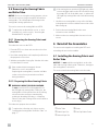
4 Prepare the Awning
This entire section prepares the awning before the FRTA
service or replacement.
4.1 Staging the Awning for all
Procedures
I
If the awning is installed on the RV, extend the FRTA
two revolutions from the awning rail.
I
See the “Open Awning” section in the Operating
Instructions (or User’s Guide) for complete
instructions.
4.2 Pinning the LH Torsion
This section applies to the torsion rods for all models,
except the 9200 and 9200 LED Power Awnings.
q
r
y
w
e
t
e
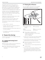
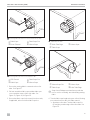
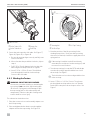
1 Pinning the LH Torsion
q
WeatherPro LH Top
Casting
r
Front Channel
w
Pin
t
Hole in Torsion Rod
e
Slots in LH End Cap
y
Cotter Pin
I
This procedure must be performed:
– with the FRTA extended two revolutions (turns)
from the awning rail, and
– while on a stepladder.
1. Pin the LH torsion to prevent uncontrolled unwinding
of the spring, or unintended awning movement.
2. Rotate the FRTA until the pin near the LH top casting is
parallel with the two slots in the LH end cap.
I
Power to the awning is required to turn the FRTA
with the awning motor.
I
The hole in the torsion rod must align with the slots
in the LH end cap.
3. Insert a 7/64 x 2-3/4 in. (3 mm x 70 mm) [or a 7/64
x 4 in. (3 mm x 102 mm) cotter pin for the power
channel] through the end cap and torsion rod. Tape
the head of the cotter pin to the end cap to secure in
place.

5
EN
Fabric Roller Tube Assembly (FRTA) Prepare the Awning
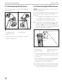
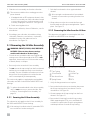
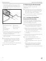
4.3 Removing the Plastic Covers
This section only applies to the 9200 and 9200 LED
Power Awnings.
q
w
w
e
e
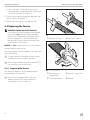
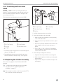
2 Removing the Plastic End Covers
q
LH Plastic Cover
e
Plastic Clip
w
RH Plastic Cover
1. Press the clip to release the LH plastic end cover.
2. Repeat for the RH cover.
4.4 Disconnecting the Wind Sensor
NOTICE: Disconnect the positive (+) 12 VDC terminal
from the supply battery.
This section only applies to the drive assembly, awning
fabric, and roller tube for models that meet these
conditions:
– the awning model is equipped with a wind sensor
– the awning model is a WeatherPro, and
– the wind sensor is mounted on the HDWR
I
To replace the weathershield or the torsion only, or
if a wind sensor is mounted on the RV (not on the
HDWR), it is not necessary to disconnect the wind
sensor. Skip to section, “Disconnecting the Awning
Motor Drive Assembly” on page6.
q
e
w
r
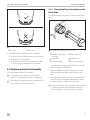
3 Disconnecting the Wind Sensor
q
Wind Sensor
e
Wind Sensor Wiring
w
Bolt and Spacer
r
Motor Wiring
1. Press and hold the red tab on the wind sensor wiring
connector. Pull the connector from the wind sensor
to disconnect.
2. If the awning will be removed to replace the awning
fabric or roller tube, disconnect the wind sensor
wiring from the control kit wiring harness.
I
Locate the connections at the wiring hole through
the RV in the RH back channel. Remove any silicone
sealant from the hole to access the connections.

6
EN
Prepare the Awning Fabric Roller Tube Assembly (FRTA)
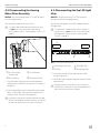
4.5 Disconnecting the Awning
Motor Drive Assembly
NOTICE: Disconnect the positive (+) 12 VDC terminal
from the supply battery.
This section disconnects the motor drive.
I
To replace the weathershield or the torsion only,
it is not necessary to disconnect the awning
motor. Skip to section, “Removing the Torsion” on
page11.
q
e
w
r
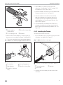
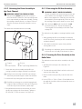
4 Disconnecting the Awning Motor
q
RH Top Casting
(Power Patio)
e
Front Channel
w
Motor Wiring
r
Hardware Wiring
1. Disconnect the awning motor from the hardware
wiring harness inside the front channel. See Figure3
& Figure4.
2. If the awning will be removed to replace the awning
fabric or roller tube, disconnect the awning motor
wiring from the control kit wiring harness.
I
Locate the connections at the wiring hole through
the RV in the RH back channel. Remove any silicone
sealant from the hole to access the connections.
4.6 Disconnecting the Top LED Light
Strip
NOTICE: Verify the positive (+) 12 VDC terminal is
disconnected from the supply battery.
This section only applies to models equipped with an
LED light strip.
I
To replace the weathershield, drive assembly, or
torsion only, it is not necessary to disconnect the
LED light strip. Skip to section, “Removing the
Torsion” on page11.
q
w
e
r
5 Disconnecting the LED Light Strip
q
Snap Caps (removed)
e
LED Light Strip
w
LED Rail
r
LED Wiring Strip
1. Disconnect the LED strip wiring from the switch
wiring inside the RV.
2. Pull the LED strip wiring through the wiring hole from
outside the RV.
I
Wiring from the RV switch may vary. See the RV
manufacturer’s instructions and wiring diagram for
the connection and location details.

7
EN
Fabric Roller Tube Assembly (FRTA) Prepare the Awning
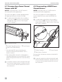
4.7 Disconnecting a Power Channel
Harness with LED
NOTICE: Verify the positive (+) 12 VDC terminal is
disconnected from the supply battery.
This section only applies to models equipped with an
LED light strip and a power channel roller tube.
I
To replace the weathershield, drive assembly, or
torsion only, it is not necessary to disconnect the
LED light strip. Skip to section, “Removing the
Torsion” on page11.
q
w
e
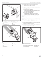
6 Power Channel Roller Tube
q
LH Top Casting (Power Patio)
e
Front Channel
w
LED/Power Channel Wiring
1. Disconnect the LED / power channel power
connector inside the LH front channel. This is a
3-place connector.
2. If the awning will be removed for awning fabric or
roller tube replacement, disconnect the LED / power
channel wiring from the electronic control kit wiring
harness.
I
Locate the connections at the wiring hole through
the RV in the LH back channel. It may be necessary
to remove silicone sealant from the hole to access
the connections.
4.8 Disconnecting a HDWR Power
Channel Harness
NOTICE: Verify the positive (+) 12 VDC terminal is
disconnected from the supply battery.
This section only applies to models equipped with
a power channel accessory strip on the HDWR front
channel.
I
To replace the weathershield, drive assembly, or
torsion only, it is not necessary to disconnect the
power channel harness. Skip to section, “Removing
the Torsion” on page11.
q
w
e
7 Hardware Power Channel Harness
q
2-Wire Connector
e
Power Channel
w
Wire Harness Connector
Disconnect the 2-wire power connector inside the RH
front channel.
I
Locate the connections at the wiring hole through
the RV in the RH back channel. It may be necessary
to remove silicone sealant from the hole to access
the connections.

8
EN
Remove Assemblies to Access the FRTA Fabric Roller Tube Assembly (FRTA)
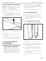
4.9 Preparing for Awning Removal
NOTICE: The area must be clean and clear of debris
to prevent fabric damage. It is not necessary to unroll
awning fabric to replace the weathershield.
This section applies to replacing the awning fabric and
roller tube.
I
To replace the weathershield, drive assembly,
or torsion only, it is not necessary to remove the
awning from the RV. Skip to section, “Removing the
Torsion” on page11.
q
w
e
8 Preparing for Awning Removal
q
TEK Screw
e
Awning Fabric
w
Awning Rail
1. Prepare an area large enough for the FRTA and
unrolled fabric.
2. Remove the TEK screws that secure the fabric at both
ends of the awning rail. Save for reinstallation.
5 Remove Assemblies to
Access the FRTA
WARNING: IMPACT, CRUSH, AND/OR PINCH
HAZARD. Failure to obey these warnings
could result in death or serious injury.
• Do not detach the awning from the RV until ties
are wrapped around each arm assembly. The arm
assemblies are under tension from the gas strut.
Detaching the awning without these ties could allow
the arms to extend quickly and unexpectedly.
• Control the arm assemblies while removing the
top screws. When the weight of the FRTA is not
supported, downward force could cause the awning
to detach, bend, or collapse.
This entire section removes assemblies to access the FRTA.
5.1 Removing the Awning
This section applies to the awning fabric and roller tube.
I
To replace the weathershield, drive assembly,
or torsion only, it is not necessary to remove the
awning from the RV. Skip to section, “Removing the
Torsion” on page11.
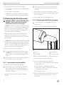
5.1.1 Detaching the Arm Assemblies
This subsection applies to the awning arm assembly.
q
w
9 Back Channel Rivets
q
Back Channel (Power Patio)
w
Rivet
I
If the HDWR is not equipped with top mounting
brackets, do not remove the two screws at the top
of the back channel.
I
If hex head screws were used instead of rivets,
remove the screws from the back channels and save
for reinstallation.
1. Remove all rivets that secure the back channels (both
ends of awning) to the RV.
2. Drill a 3/16 in. (5 mm) diameter hole through the rivet
center.

9
EN
Fabric Roller Tube Assembly (FRTA) Remove Assemblies to Access the FRTA
a. Discard the rivet and debris.
b. Repeat step 2 for each rivet securing the back
channel to the RV.
q
w
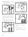
10 Power Patio HDWR with Top Mounting Brackets
q
Hex Head Screw
w
Top Mounting Bracket
3. With one person holding each arm assembly, remove
the hex head screws (from the inside slot) that secure
the top mounting brackets (both ends of the awning)
to the RV.
I
Some awning models do not have top mounting
brackets. Instead, the hex head screws are secured
through holes in the top of the back channel. See
Figure11 & Figure12.
q
w
11 WeatherPro Hardware with Top Mounting Brackets
q
Hex Head Screw
w
Top Mounting Bracket
q
w
12 Sport HDWR without Top Mounting Brackets
q
Hex Head Screw
w
Back Channel
q
r
w
e
t
13 WeatherPro Hardware Secured with Nylon Ties
q
Top Mounting Bracket
r
Top Casting
w
Front Channel
t
Back Channel
e
Nylon Ties
4. Push the front channel to close against the back
channel, and hold in place.
5. Wrap at least two nylon ties around the front and
back channel near the top casting. Tape in place.

10
EN
Remove Assemblies to Access the FRTA Fabric Roller Tube Assembly (FRTA)
q
w
e
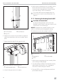
14 Power Patio HDWR Secured with Nylon Tie
q
Front Channel
e
Back Channel
w
Nylon Tie
6. Wrap at least one nylon tie around the front and back
channel near the bottom of the arm assembly. Tape in
place.
7. Repeat steps 4 through 6 for the opposite side.
q
w
15 Power Patio HDWR with Top Mounting Brackets
q
Top Mounting Bracket
w
Hex Head Screw
8. Verify all safety precautions are in place.
9. With one person holding each arm assembly, remove
the hex head screws (from the outside slot) that
secure the top mounting brackets to the RV at both
ends of the awning. Save for reinstallation.
I
For models without top mounting brackets, hex
head screws are used to secure the brackets. See
Figure12.
5.1.2 Removing the Awning from the RV
CAUTION: LIFTING HAZARD.
Use proper liing technique and control when
liing the awning. Failure to obey this caution could
result in minor or moderate injury.
NOTICE: Keep both arm assemblies parallel to each
other to avoid twisting and damaging the awning.
This subsection removes the awning from the RV.
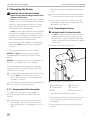
w
e
q
16 Liing the Awning
q
Awning Rail
e
Arm Assembly
w
FRTA
1. With one person grasping each arm assembly, li the
entire awning assembly upright.
2. Carry the awning assembly forward until the awning
fabric (with the awning roller cover, if equipped)
slides free from the awning rail on the RV.
3. Place the FRTA on a clean, well protected surface to
prevent fabric damage.

11
EN
Fabric Roller Tube Assembly (FRTA) Remove Assemblies to Access the FRTA
5.2 Removing the Torsion
WARNING: IMPACT OR PINCH HAZARD.
Failure to obey these warnings could result in
death or serious injury.
• Do not remove the top casting from the front channel
until the torsion rod is securely pinned at the end cap.
Otherwise, rapid casting spin off will occur. Spring
tension will attempt to spin the top casting and/or
roller tube quickly and unexpectedly.
• Do not remove the top casting from the front channel
until the ties are wrapped securely around each arm
assembly. The arm assemblies are under tension from
the gas strut. Removing these ties could allow the
arms to extend quickly and unexpectedly.
• Use extreme care when winding or unwinding the
top casting. If not controlled, rapid casting spin off
will occur.
• Be sure nylon ties secure the LH arm assembly.
NOTICE: Do not allow the top casting to spin off
if equipped with an LED and Power Channel wiring
harness.
NOTICE: Be sure the LH torsion is securely pinned. See
the section, “Pinning the LH Torsion” on page4.
This section applies to the awning fabric, roller tubes,
and torsion rods for all models, except the 9200 and
9200 LED Power Awnings.
I
To replace the weathershield or the drive assembly
only, it is not necessary to unwind or remove
torsion. Skip to the section, “Removing the Drive
Assembly” on page14.
I
If the awning is installed on the RV, extend the FRTA
two revolutions from the awning rail.
5.2.1 Securing the LH Arm Assembly
This subsection secures the LH arm assembly for
all models, except the 9200 and 9200 LED Power
Awnings.
I
If the awning is removed from the RV and the LH
arm assembly is already secured with nylon ties,
skip to the subsection, “Unwinding the Torsion” on
page11.
1. Push the front channel against the back channel to
close.
I
Allow room between the front and back channels
to remove the top casting from the front channel.
2. Wrap at least two nylon ties around the front and
back channel near the top mounting bracket, and
tape in place. See Figure13.
5.2.2 Unwinding the Torsion
WARNING: IMPACT OR PINCH HAZARD.
Do not remove the cotter pin from the torsion rod
(at the end cap) until the top casting is securely
held. Otherwise, rapid casting spin off will occur.
Failure to obey this warning could result in death or
serious injury.
This subsection unwinds the torsion rod.
q
r
w
e
y
t
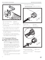
17 WeatherPro HDWR Top Casting Removal
q
LH Top Casting
r
LH End Cap
w
Front Channel
t
Cotter Pin
e
Rivet
y
Hex Head Screw
1. Verify all safety precautions are in place.
2. Remove the hex head screw and washer that secure
the LH top casting to the front channel. Save for
reinstallation.
3. Li and separate the LH top casting from the front
channel.

12
EN
Remove Assemblies to Access the FRTA Fabric Roller Tube Assembly (FRTA)
q
w
r
e
18 Power Patio HDWR with Torsion Crank Assembly
q
Torsion Crank Assembly
e
Adapter
w
LH Top Casting
r
Crank Handle
4. Place the correct torsion crank assembly adapter over
the LH top casting.
5. Place and tighten the hex head screw through the
adapter and into the top casting. See Figure18.
6. While keeping a firm hold on the crank handle, pull
the cotter pin from the torsion rod at the LH end cap.
See Figure1 & Figure18.
7. Slowly unwind the torsion (top casting) until all
torsion spring tension is relaxed. Then remove the
crank assembly from the LH top casting.
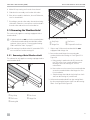
5.2.3 Removing the Old Torsion
WARNING: IMPACT OR PINCH HAZARD.
Do not remove the torsion rod from the roller
tube until spring tension is released (unwound).
If the torsion rod is not pinned at the end cap, a
rapid casting spin off will occur. Spring tension
will attempt to spin the top casting and/or end
cap quickly and unexpectedly. Failure to obey this
warning could result in death or serious injury.
This subsection removes the torsion rod.
1. With the torsion spring tension released, remove the
three rivets that secure the LH end cap to the roller
tube. See Figure17.
a. Drill a 3/16 in. (5 mm) diameter hole through the
center of the rivet.
b. Discard the rivet and debris.
c. Repeat step 1 for each rivet that secures the end
cap to the roller tube.
q
w
r
e
19 Sliding Out the Torsion Assembly
q
Roller Tube
e
Stabilizer
w
Torsion Assembly
r
Awning Fabric
q
w
e
r
t
20 Sliding out the Power Channel Wiring with LED
q
Power Channel Wiring
Harness with Silver Marking
r
Roller Tube
w
Power Torsion Assembly
t
Awning Fabric
e
Stabilizer

13
EN
Fabric Roller Tube Assembly (FRTA) Remove Assemblies to Access the FRTA
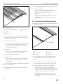
2. Slide the torsion assembly out from the roller tube.
I
The connector with the silver marking goes to the
power channel.
a. If equipped with an LED and power channel, slide
the torsion assembly out of the roller tube enough
to access the connectors on the powered torsion
assembly. Unplug the connectors. See Figure20.
b. Finish removing the torsion.
3. If the torsion is defective, discard. Otherwise, save for
reinstallation.
4. If installing a new roller tube, discard the existing
roller tube. Otherwise, remove burrs, rivet bodies,
and debris from the roller tube and save for
reinstallation. See Figure19.
5.3 Removing the LH Idler Assembly
WARNING: IMPACT, CRUSH, AND/OR PINCH
HAZARD. Failure to obey these warnings
could result in death or serious injury.
• Control the arm assemblies while removing the top
casting screws. When the weight of the FRTA is not
supported, downward force could cause the awning
to detach, bend, or collapse.
• Be sure nylon ties secure the LH arm assembly.
• Do not remove the top casting from the front channel
until the ties are wrapped securely around each arm
assembly. The arm assemblies are under tension from
the gas strut. Removing these ties could allow the
arms to extend quickly and unexpectedly.
This section only applies to replacing the awning fabric,
roller tube, and idler for the 9200 and 9200 LED Power
Awnings.
I
To replace the weathershield or the drive assembly
only, it is not necessary to remove the idler. Skip
to section, “Removing the Drive Assembly” on
page14.
5.3.1 Securing the LH Arm Assembly
This subsection only applies to the LH arm assembly for
the 9200 and 9200 LED Power Awnings.
I
If the awning is installed on the RV, extend the FRTA
two revolutions from the awning rail.
1. Push the front channel to close against the back
channel.
I
Allow enough room between the front and back
channels to remove the top casting from the front
channel.
2. Wrap at least two nylon ties around the front and
back channel near the top mounting bracket. Tape in
place. See Figure13.
5.3.2 Removing the Idler from the LH Arm
This subsection only applies to removing the idler from
the 9200 and 9200 LED Power Awnings.
q
w
t
i
y
r
u
e
21 Removing the LH Idler Arm
q
Top Casting
t
Slic Pin
w
Front Channel
y
LH End Cap
e
Hex Head Screw
u
Rivet
r
Spring Detent
i
FRTA
1. Verify all safety precautions are in place.
2. Remove the hex head screw and washer that secure
the LH top casting to the front channel. Save for
reinstallation. See Figure18.
3. Li and separate the LH top casting from the front
channel. See Figure21.
4. Remove the LH end cap from the LH top casting.
While supporting the FRTA, use a small flathead
screwdriver to push in the Slic pin’s spring detent
until the pin releases from the LH top casting.

14
EN
Remove Assemblies to Access the FRTA Fabric Roller Tube Assembly (FRTA)
5. Remove the LH end cap from the roller tube:
a. Drill a 3/16 in. (5 mm) diameter hole through the
rivet center.
b. Discard the rivet and debris.
c. Repeat steps a and b for each rivet securing the
end cap to the roller tube. Remove the end cap.
5.4 Removing the Drive Assembly
WARNING: IMPACT, CRUSH, AND/OR PINCH
HAZARD. Failure to obey these warnings
could result in death or serious injury.
• Do not remove the top casting from the front channel
until the torsion rod is securely pinned at the end cap.
Otherwise, rapid casting spin off will occur. Spring
tension will attempt to spin the top casting and/or
end cap quickly and unexpectedly.
• Make sure the LH torsion is securely pinned. See
subsection, “Pinning the LH Torsion” on page4.
If LH torsion was removed from the FRTA, proceed to
the next bullet.
• Do not remove the top casting from the front channel
until the ties are wrapped securely around each arm
assembly. The arm assemblies are under tension from
the gas strut. Removing these ties could allow the
arms to extend quickly and unexpectedly.
This section removes the drive assembly.
I
To replace the weathershield or the torsion only,
it is not necessary to remove the drive assembly.
Skip to section, “Removing the Weathershield” on
page15.
I
If the awning is installed on the RV, extend the FRTA
two revolutions from the awning rail.
5.4.1 Securing the Arm Assemblies
This subsection secures the LH arm assembly.
I
If the awning is removed from the RV and the RH
arm assembly is already secured with nylon ties,
skip to the subsection, “Removing the Old Drive
Assembly” on page14.
1. Push the front channel to close against the back
channel.
I
Allow enough room between the front and back
channel to remove the top casting from the front
channel.
2. Wrap at least two nylon ties around the front and
back channel near the top mounting bracket. Tape in
place. See Figure13.
3. Repeat steps 1 and 2 for the opposite side.
5.4.2 Removing the Old Drive Assembly
I
The end cap and motor assemblies may vary in
appearance.
This subsection removes the existing drive assembly.
q
w
e
t
y
r
22 Rivets on the RH End Cap
q
Rivet
r
RH Head Cap
w
Roller Tube
t
Hex Head Screw
e
RH Top Casting WeatherPro
y
Front Channel
1. Verify all safety precautions are in place.
2. Remove the RH end cap to the roller tube.
a. Drill a 3/16 in. (5 mm) diameter hole through the
center of the rivet.
b. Remove the rivet with debris and discard.
c. Repeat steps a and b for each rivet securing the
end cap to the roller tube.
d. Remove the end cap.
3. Remove the hex head screw and washer that secure
the RH top casting to the front channel. Save for
reinstallation.

15
EN
Fabric Roller Tube Assembly (FRTA) Remove Assemblies to Access the FRTA
4. Li the RH top casting out from the front channel.
5. Slide the drive assembly out from the roller tube.
6. If the drive assembly is defective, discard. Otherwise,
save for reinstallation.
7. If installing a new the roller tube, discard the existing
roller tube. Otherwise, remove burrs and rivet debris
from the roller tube and save for reinstallation.
5.5 Removing the Weathershield
This section only applies to awnings equipped with a
weathershield.
I
If replacement does not involve the weathershield
or if both the weathershield and the fabric will be
replaced, skip to section, “Removing the Awning
Fabric and Roller Tube” on page17.
I
If the awning is installed on the RV, extend the FRTA
two revolutions from the awning rail.
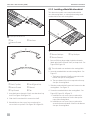
5.5.1 Removing a Metal Weathershield
This subsection only applies to awnings equipped with a
metal weathershield.
q
w
e
t
r
23 Metal Hinge Slat
q
Vinyl Strip
r
Slat Screw
w
TEK Screw
t
Hinge Slat
e
Awning Rail
Slat “B”
Slat “B”
Slat “B”
Slat “B”
Slat “A”
q
w
e
r
24 Obsolete Metal Weathershield
q
Vinyl Strip
e
Slat Screw
w
Hinge Slat
r
Crimped End or Rivet
1. Skip to step 3 if the metal weathershield is not
equipped with a hinge slat.
2. Remove the metal hinge slat connecting the
weathershield to the awning rail. See Figure23 &
Figure24.
a. If the awning is attached to the RV, remove the
two TEK screws (one at each end) that secure
the hinge slat to the awning rail. Save for
reinstallation.
b. Remove the two slat screws (one at each end) that
secure the weathershield to the hinge slat. Save
for reinstallation.
c. Slide the hinge slat with the vinyl strip from slat A
and from the awning rail, and discard.
3. Unfasten the weathershield from the awning fabric
by disconnecting the bottom slat B from the awning
fabric. See Figure24 & Figure25.

16
EN
Remove Assemblies to Access the FRTA Fabric Roller Tube Assembly (FRTA)
Slat “B”
Slat “A”
Slat “B”
Slat “B”
Slat “B”
e
q
w
25 Metal Weathershield
q
Set Screw, Crimped End,
or Rivet
e
Awning Rail
w
Slat Screw
4. Disconnect the bottom slat B from the awning fabric
using one of the procedures (below) based on how
the slat ends are attached:
• Set screw fastened ends:
a. Remove the two set screws (one at each end) that
secure the slat to the awning fabric and discard.
b. If keeping the old weathershield, save the set
screws for reinstallation.
• Riveted ends:
a. Drill a 1/8 in. (3 mm) diameter hole through the
rivet center of the slat (one at each end).
b. Discard the rivets and debris.
• Crimped ends:
a. Use a screwdriver to spread open the crimped
ends (one at each end) that secure the slat to the
awning fabric.
I
If the metal weathershield is equipped with a hinge
slat, skip to step 6.
5. Repeat step 4 to disconnect the top slat A from the
awning fabric.
6. Slide the weathershield from the awning fabric. See
Figure24 & Figure25.
a. If the weathershield is damaged or being
replaced, discard and skip to section “Removing
the Awning Fabric and Roller Tube” on
page17.
b. If reusing the weathershield, place on a clean,
well protected surface to prevent damage for
reinstallation.
5.5.2 Removing a Vinyl Weathershield
This subsection only applies to awnings equipped with a
vinyl weathershield.
q
w
e
r
26 Vinyl Weathershield
q
Bottom Hinge
e
Vinyl Panel
w
Set Screw
r
Top Hinge
1. Remove the two set screws (one at each end) that
secure the top hinge to the awning fabric and
discard.
2. Remove the two set screws (one at each end) that
secure the bottom hinge to the fabric and discard.
3. Slide the weathershield from the awning fabric.
a. If the weathershield is damaged or being
replaced, discard it and the top and bottom set
screws. Continue with the section “Removing the
Awning Fabric and Roller Tube” on page17.
b. If reusing the weathershield, place on a clean,
well protected surface to prevent damage for
reinstallation.

17
EN
Fabric Roller Tube Assembly (FRTA) Reinstall the Assemblies
5.6 Removing the Awning Fabric
and Roller Tube
NOTICE: Before servicing the awning, prepare a clean
and smooth work area large enough for the unfurled
awning fabric. This will help prevent damage to the
awning fabric during replacement.
This section removes the awning fabric and FRTA.
I
To replace the weathershield, torsion, or drive
assembly only, see the section, “Removing the
Weathershield” on page15.
5.6.1 Removing the Awning Fabric and
Roller Tube
This subsection removes the FRTA.
1. Place the FRTA on a clean and smooth work surface
prepared earlier.
2. Unroll the awning fabric until completely unfurled on
the prepared work surface.
3. With the awning fabric laying flat, slide the roller tube
from the fabric to remove.
I
If the weathershield is damaged, discard.
Otherwise, save for reinstallation.
If replacing the awning fabric, leave the old fabric
on the work surface to protect the new fabric
during installation.
5.6.2 Preparing the New Awning Fabric
WARNING: IMPACT OR CRUSH HAZARD.
Do not remove the LED rail (if equipped) from
the LED light strip awning fabric. Otherwise, the
awning fabric could separate from the RV awning
rail and cause the awning to extend quickly,
resulting in detaching, bending, or collapsing.
Failure to obey this warning could result in death or
serious injury.
This subsection prepares the new fabric.
I
To replace the roller tube only, skip to section,
“Installing the Awning Fabric and Roller Tube” on
page17.
I
If the awning has an undesired LED light strip, either
remove the light strip from the LED rail while leaving
the empty LED rail on the fabric rope, or replace the
LED light strip awning fabric with a standard awning
fabric.
1. Unroll the new awning fabric on top of the old fabric
in the prepared work area with the bottom side of the
fabric facing up.
2. Position the new awning fabric in the same
orientation as the old fabric.
3. Make sure the new awning fabric size and color are
correct.
6 Reinstall the Assemblies
This entire section applies to installing the FRTA and
reinstalling the removed assemblies.
6.1 Installing the Awning Fabric and
Roller Tube
NOTICE: Do not install the awning fabric on the roller
tube without using a fabric guide. Otherwise, damage to
the awning fabric could occur.
This section installs the awning fabric and roller tube.
q
t
w
e
r
27 Using the End Cap Fabric Guide
q
Roller Tube
r
Notch
w
Fabric Rope Slot
t
End Cap Fabric Guide
e
Valance Rope Slot

18
EN
Reinstall the Assemblies Fabric Roller Tube Assembly (FRTA)
1. Align the fabric rope and valance rope slots of the
end cap fabric guide to the corresponding slots on
the roller tube. Place the guide on the open end of
the roller tube.
w
r
u
t
y
e
q
28 Feeding the Fabric into the Roller Tube
q
End Cap Fabric Guide
t
Fabric Rope
w
Notch
y
Fabric Rope Slot
e
Valance Rope Slot
u
Roller Tube
r
Valance Rope
2. Insert the fabric rope and valance rope of the awning
fabric into corresponding slots on the roller tube
through the end cap fabric guide.
3. Slide the roller tube forward until the awning fabric is
centered on the tube.
I
The awning fabric will feed into the roller tube’s
slots while moving the roller tube forward. The
awning fabric will be secured to the roller tube
when the torsion is reinstalled.
4. Remove the end cap fabric guide from the roller tube.
I
Save the guide for future adjustments.
6.2 Replacing the Weathershield
This section only applies to awnings with a
weathershield.
I
If replacement does not involve a weathershield or
if the weathershield is pre-installed on the awning
fabric, skip to section, “Preparing for the Torsion,
Idler, and Drive Replacement” on page20.
I
If the awning is installed on the RV, extend the FRTA
two revolutions from the awning rail.
6.2.1 Preparing an Existing Metal
Weathershield for New Fabric
This subsection only applies if keeping the old metal
weathershield (equipped with a hinge slat) to reinstall
onto new awning fabric. See Figure23.
I
If the old metal weathershield will be discarded, or
has no more than five slats, skip to the subsection,
“Installing a Metal Weathershield” on page19.
1. Remove slat A from the weathershield. See Figure25.
a. Remove the two slat screws (one at each end) that
secure slat A to top slat B and discard.
b. Slide slat A from the weathershield. Save for
reinstallation.
2. Remove the extra slats from the awning rail end of the
old weathershield. See Figure25.
I
Slat A is counted in the number of slats.
a. If the old weathershield has seven slats, then
remove two B slats.
b. If the old weathershield has six slats, remove one
B slat.
c. Remove the two slat screws (one at each end)
that secure the extra B slat(s) to the remaining
weathershield slats. Save for reinstallation.
d. Slide the extra B slat(s) from the weathershield and
discard.

19
EN
Fabric Roller Tube Assembly (FRTA) Reinstall the Assemblies
Slat “B”
Slat “B”
Top Slat “B”
Slat “B”
Slat “A”
q
w
e
29 Preparing the Weathershield
q
Tab
e
Slat Screw
w
Bottom Channel
q
r
w
t
e
y
30 Preparing the Slats
q
Slat A (Top Slat)
r
Slat B (Typical Slat)
w
Bottom Channel
t
Channel
e
Top Channel
y
Tab
3. Insert the bottom channel of slat A onto the tab of top
slat B. See Figure29 & Figure30.
4. Slide slat A forward until it is centered on slat B.
5. Reinstall the two slat screws (one at each end) to
secure slat A to top slat B. See Figure25 & Figure29.
6.2.2 Installing a Metal Weathershield
This subsection installs a new metal weathershield
onto old awning fabric, or reinstalls the existing metal
weathershield onto new awning fabric.
“B”
“A”
q
w
e
31 Inserting the Weathershield onto the Awning Fabric
q
Bottom Slat Rope
e
Top Slat Rope
w
Bottom Channel
1. Remove (file) any sharp edges inside the channels
(both open ends) of bottom slat B, and top slat A. See
Figure25 & Figure30.
I
These channels are attached to the awning fabric.
2. Insert the weathershield onto the awning fabric. See
Figure31.
a. The bottom channel of slat B corresponds to the
bottom slat rope of awning fabric.
b. The top channel of slat A corresponds to the top
slat rope of awning fabric.
3. Slide the weathershield forward until centered on the
awning fabric. See Figure31.
4. Secure the weathershield to the awning fabric. See
Figure25, Figure30, & Figure31.
a. Install the two set screws (one at each end) to
secure the top channel of slat A to the top slat
rope of the awning fabric.
b. Install the two set screws (one at each end) to
secure the bottom channel of slat B to the bottom
slat rope of awning fabric.

20
EN
Reinstall the Assemblies Fabric Roller Tube Assembly (FRTA)
6.2.3 Installing a Vinyl Weathershield
This subsection installs a new vinyl weathershield
onto old awning fabric, or reinstalls the existing vinyl
weathershield onto new awning fabric.
q
e
r
t
w
32 Installing Vinyl Weathershield
q
Bottom Slat Rope
r
Top Slat Rope
w
Bottom Channel
t
Top Hinge
e
Bottom Hinge
1. Insert the weathershield onto the awning fabric.
a. The bottom channel of the (bottom) hinge
corresponds to the bottom slat rope of awning
fabric.
b. The top channel of the (top) hinge corresponds to
the top slat rope of awning fabric.
2. Slide the weathershield forward until centered on the
awning fabric.
3. Secure the weathershield to the awning fabric. See
Figure26 & Figure32.
a. Install the two set screws (one at each end) to
secure the top channel of the top hinge to the top
slat rope of awning fabric.
b. Install the two set screws (one at each end) to
secure the bottom channel of the bottom hinge to
the bottom slat rope of awning fabric.
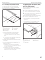
6.3 Preparing for the Torsion, Idler,
and Drive Replacement
This section applies to the torsion, idler, and drive
assembly replacement.
I
If only the weathershield was replaced, skip to
section “Complete the Installation” on page29.
I
If the awning is installed on the RV, extend the FRTA
two revolutions from the awning rail.
The following steps apply to both old and new awning
fabric. However, completing these steps varies:
• New awning fabric: The following steps must be
performed.
• Old awning fabric: The following steps must be
reviewed to verify the installation is correct.
q
w
e
33 Reviewing Fabric Placement on a Roller Tube
q
Fabric Rope Slot
e
Valance Rope
w
Fabric Rope
Strona się ładuje...
Strona się ładuje...
Strona się ładuje...
Strona się ładuje...
Strona się ładuje...
Strona się ładuje...
Strona się ładuje...
Strona się ładuje...
Strona się ładuje...
Strona się ładuje...
Strona się ładuje...
Strona się ładuje...
-
 1
1
-
 2
2
-
 3
3
-
 4
4
-
 5
5
-
 6
6
-
 7
7
-
 8
8
-
 9
9
-
 10
10
-
 11
11
-
 12
12
-
 13
13
-
 14
14
-
 15
15
-
 16
16
-
 17
17
-
 18
18
-
 19
19
-
 20
20
-
 21
21
-
 22
22
-
 23
23
-
 24
24
-
 25
25
-
 26
26
-
 27
27
-
 28
28
-
 29
29
-
 30
30
-
 31
31
-
 32
32


Dometic FRTA Assembly Instrukcja instalacji
- Typ
- Instrukcja instalacji
w innych językach
Powiązane artykuły
Inne dokumenty
-
Luxor LOTM Instrukcja obsługi
-
-
Shimano FC-P100 Exploded View
-
ROOMS TO GO 12409288 Assembly Instructions
-
AMERICANA AVL3548W Instrukcja instalacji
-
Sea Ray 2008 Sundancer 330 Parts Manual
-
-
-
-