
Szerviz
A problémák megoldására vonatkozó információkat a
www.dexaplan.com oldalon találja.
Szervizünkkel vegye fel a kapcsolatot e-mailben
550 660, hétf t l péntekig 9:00 17:00). Ott az összes
szükséges információt megkapja a szervizeléssel,
visszaküldéssel, stb. kapcsolatos kérdéseire.
- -
-
õ õ
Dexaplan GmbH, Paul-Böhringer-Str. 3, D - 74229 Oedheim
Kiadás: 12/10/2007
Azonosító szám: 12-10-2007-VT 623-GBPLHU L74a
VIDEO DOOR INTERCOM
VIDEO DOOR ENTRY SYSTEM VT 623
WIDEODOMOFON VT 623
VIDEÓ KAPUTELEFON VT 623
Operating and safety instructions page 2
Wskazówki dotycz ce obs ugi i bezpiecze stwa Strona 11
Használati utasítás és biztonsági el rások Oldal 20
¹ ³ ñ
õí
GB
IE
L74a
Contents
Introduction ..................................................... Page 2
Proper use Page 2
Package contents Page 2
Equipment Page 4
Technical data Page 4
Safety instructions Page 5
Planning the installation Page 5
Checking function Page 6
Preparing wall mounting Page 6
Connections Page 7
.......................................................
............................................
.......................................................
.................................................
...........................................
..................................
............................................
..................................
....................................................
Finishing the wall mounting Page 7
First use Page 7
Operation Page 7
Settings Page 8
Maintenance + cleaning Page 10
Disposal Page 10
Warranty Page 10
.............................
..........................................................
........................................................
...........................................................
Troubleshooting ...............................................Page 9
..................................
..........................................................
..........................................................
Service ............................................................ Page 10
Introduction
Proper use
Read through these operating instructions completely
and carefully and while doing so fold out page 3 with
the illustrations. The operating instructions are an
integral part of the product and contain important
information about operation and handling. Always
observe all the safety instructions. If you have any
questions or are unsure about using the equipment,
ask a specialist, obtain internet information under
www.dexaplan.com or contact the service office. Keep
these instructions in a safe place and pass them on to
third parties if necessary.
This video door entry system VT 623 consists of an
outside station VT 623C and an indoor station VT 623M
which are connected using a two connection
cable. The maximum cable length is 75 m.
The power supply is provided using the supplied mains
adapter which is connected to the indoor station. A
chime (selectable) is heard at the indoor station when
the doorbell button is pressed. After pressing a button
on the indoor station, two-way hands free conversation
is enabled.
When the doorbell button is pressed, the camera
installed in the outdoor station is activated
automatically and the camera image is displayed on
the monitor of the indoor station. The camera can be
activated for observation by pressing a button on the
indoor station: two-way conversation can also be
established thereafter.
The camera image is displayed in colour. The infrared
illumination integrated in the outdoor station is
activated during darkness to illuminate the face of the
person standing in front of the camera. This image is
-core
displayed in black and white. The image quality in bad
light conditions will be improved by additional lighting.
A powered speaker (not supplied) can be connected to
the indoor station in order to amplify the chime and the
conversation and/or relay it to another place.
An electric 12 V DC door release (not supplied) can be
connected to the outdoor station if desired. This can be
activated at the indoor station by pressing a button. The
system is intended for wall mounting whereby the
indoor station and the mains adapter are only approved
for indoor use. A wedge bracket is supplied for
alignment of the outdoor station. The system is only for
private use and not for commercial use.
Any other use or modification of the equipment is not
authorised and presents significant risks of accident.
No liability will be accepted for consequential damages
or for damages caused by improper use or incorrect
operation.
Check the package contents are complete and that the
equipment is undamaged immediately after unpacking.
1x indoor station (incl. wall bracket)
1x outdoor station (incl. wall bracket)
1x two-core connection cable, approx. 15 m
1x bracket for outdoor station
1x mains adapter with approx. 2.5 m cable
8x mounting screws
8x wall plugs Ø 5 mm
4x fixing screws for bracket
3x fixing
1x spare fuse
1x spare nameplate
1x operating and safety instructions
Package contents
shaped
wedge shaped
wedge shaped
screws
PL
HU
Hibaelhárítás
Hiba
Nincs kép és nem világít a
bekapcsolásjelz
A cseng gomb megnyomására
semmi se történik, a monitorgomb
megnyomására a „NO SIGNAL”
felirat jelenik meg és a
bekapcsolásjelz pirosan világít.
A cseng gomb vagy a monitor
gomb megnyomására a „NO
SIGNAL” felirat jelenik meg és a
bekapcsolásjelz pirosan világít.
A csng gomb megnyomása után
nem jelenik meg a kép, a
bekapcsolásjelz zölden világít
Sípoló hang hallatszik
Nincs hang
A kép fekete/fehér és villódzik
Alkonyatkor / sötétben a kép sötét
A kép nappal is sötét
A monitor képe világos hátteret
mutat, a látogató azonban
sötétnek látszik
õ
õ
õ
õ
õ
õ
õ
Elhárítás
Ellen rizze az áramellátást
A beltéri egység hátoldalából húzza ki a
biztosítékházat (52) és cserélje ki a
biztosítékot azonos típusúra és érték re
(1 db tartalék biztosítékot talál a csomagban)
Helyesbítse a bekötés polaritását
Ellen rizze a bekötés létét és helyességét
Használjon alkalmas kábelt
(érkeresztmetszet min. 0,75 mm , hossz
max. 75 m).
Módosítsa a beállításokat a Beállítások
menüben
Helyezze távolabb egymástól a bel- és kültéri
egységet
Halkítsa le a beltéri egység hangerejét
Állítsa be a beltéri egység hangerejét
Ellen rizze az áramellátást
Ellen rizze a bekötés létét és helyességét
Helyesbítse a bekötés polaritását
Kapcsolja be és ki a monitort a monitor
gombbal (38).
Állítsa készüléket PAL rendszerre
Helyezzen el kiegészít megvilágítást
Módosítsa a beltéri egység felszerelési
magasságát vagy állítsa be a monitor
fényerejét
Helyezzen el kiegészít megvilágítást vagy
módosítsa a kültéri egység felszerelésének
helyét
õ
û
õ
õ
õ
õ
õ
2
Ok
Nincs áramellátás|
Kiolvadt a biztosíték
Helytelen a két állomás között a
polaritás
Megszakad a két állomás közötti
összeköttetés
A kábel túl hosszú vagy kicsi a
keresztmetszete
A beállításokra „fekete” képerny jelenik
meg
Akusztikus visszacsatolás miatt jön létre
Túl halk a beltéri egység hangerejének
beállítása
Nincs áramellátás
Megszakad a két állomás közötti
összeköttetés
Helytelen a két állomás között polaritás
Nem megfelel a videójel kialakítása
Nem megfelel videórendszert állított be
A kültéri egységnek kiegészít fényre
van szüksége a megfelel kép
továbbításához
Kedvez tlen szögb l nézi a monitort
Nagyon ellenfényes a képkivágás
õ
õ
õ
õ
õ
õ õ
készülék díjtalan beküldése. Ez a garancia csak az els
vásárlót illeti meg, nem ruházható át. A garanciavállalás
csak a gyártási és anyaghibákra vonatkozik. Nem
vonatkozik a kopó és eltört alkatrészekre. A termék csak
magáncélú használatra készült, nem hivatásos célra.
Szakszer tlen és / vagy nem rendeltetésszer használat,
er szakos behatás és nem a szerviz által végzett
beavatkozás esetén megsz nik a garancia. Jelen
garanciális feltételek nem érintik az Ön törvényes jogait.
õ
û û
õ
û
HU
GB / IE - 2HU - 26

Equipment
Package contents (see Fig. A):
Outdoor station front side (see Fig. B):
Outdoor station rear side (see Fig. C):
Outdoor station wall bracket (see Fig. D):
Wall bracket fixing for outdoor station on wedge
shaped bracket (see Fig. E):
Indoor station front side (see Fig. F):
1 outdoor station
2 indoor station
3 wall bracket for indoor station
4 fixing screws
5 fixing for wedge shaped bracket
6 spare fuse
7 spare nameplate
8 wall plugs for indoor station
9 mounting screws for indoor station
10 mounting screws for outdoor station
11 wall plugs for outdoor station
12 mains adapter
13 low-voltage connector
14 connection cable
15 bracket for outdoor station
16 wall bracket for outdoor station
17 infrared LEDs
18 camera lens
19 loudspeaker
20 illuminated nameplate cover
21 doorbell button
22 microphone
23 terminal cover
24 grommet
25 cable channel
26 tab
27 hole for mounting screw
28 cable opening (for laying along the wall)
29 cable opening (for laying through the wall)
30 hole for fixing
31 hole for mounting screw
32 cable opening
33 monitor
34 loudspeaker
35 operating status LED
36 talk button
37 door release button
38 monitor button
39 microphone
40 reduce volume button
41 increase volume button
42 image adjustment button
screws
wedge shaped
screw
Indoor station side (see Fig. G):
Indoor station wall bracket (see Fig. H):
Connection diagram (see Fig. I):
Outdoor station VT 623C
Indoor station VT 623M
43 chime switch
44 chime volume switch
45 hole for mounting screw
46 cable opening
47 hole for fixing
48 optional powered loudspeaker (not supplied)
49 keyhole slot
50 connection for low-voltage current
51 cable channel
52 fuse holder
53 terminal for powered loudspeaker
54 terminal for powered loudspeaker
55 connecting cable terminal
56 connecting cable
57 connection for optional electric door release
58 connection for optional electric door
59 connecting cable
60 connecting cable
61 nameplate
62 optional electric door (not supplied)
Operating voltage: from the indoor station
(15 V DC)
Power consumption: max. 1A
Voltage for door : 12 V DC (max. 1 A) *
Camera image sensor: 1/3“ CMOS colour
Camera image resolution: 628 x 562 pixels (PAL)
Camera lens: f = 4.5 mm
Camera angle of view: approx. 64° horizontal,
approx. 48° vertical
Illumination: 9 infrared LEDs (for illumination of
the close range during darkness)
Twilight switch: activates infrared LEDs at approx.
2 Lux
Dimensions: approx.104 x 185 x 46 mm incl.
wall bracket
Casing material: PC, ABS
Weight: approx. 333 g incl. wall bracket
Operating temperature: -10 °C to +50 °C
Protection class: IP 55
* The door opener must meet these specifications
Operating voltage: 15 V DC
Power consumption: max. 1.5A
Fuse: 250 V, 3 A; delayed action
Ring tone: max. 68 dB(A) (at distance of 1 m)
Technical data
screw
terminal
release
terminal
terminal
release
V
release
B
C D
F
I
G
10
15
17
18
19
20
21
22
23
24
25
26
27
16
16
28
29
30
33
34
35
36
37
38
39
40
41
42
43
44
E
31
48
49
50
2
51
52
61
1
60
59
58
57
53
54
55
56
62
45
46
47
H
9
3
5 10
32
A
1 2 3
4
5
6789101112
15
13
16
14
GB / IE - 3 GB / IE - 4
HU - 25
A
A
B
B
+
1/2/3
+
monitor képe.
A beállításokhoz lesz elég ideje, ha a monitor
bekapcsolása után megnyomja a beszéd gombot
(36), mert ez után a monitor kb. 4 percig bekapcsolva
marad.
Ha halkabb csengetési hangot akar, állítsa a hanger
kapcsolót (44) „-” állásba, ha hangosabbat, a
„+” állásba.
Kapcsolja be a monitort a monitor gombbal
(38).
A cs en g e t ési é s b e s zé dh a n g e r e j é ne k
hangosításához nyomja meg a hanger gombot
(41), a halkításhoz a hanger gombot
(40). (A beállított értéket a monitor mutatja: 0
100 között.)
A cseng hang kapcsolóval (43) választhatja ki a
három cseng hang valamelyikét.
Kapcsolja a cseng hangválasztó kapcsolót a három
állás valamelyikére.
1. állás 2x “Ding-Dong”
2. állás rövid hangsor
3. állás hosszú hangsor „Für Elise”
A készülék nem igényel karbantartást.
Rendszeresen ellen rizze a m ködést és a m szaki
biztonságot.
A felületek tisztításához használjon száraz rongyot. A
makacs szennyez déseket enyhén megnedvesített
ronggyal törölje le, tisztítószerek használata nélkül.
A hangszóró (19 ill. 34) réseit óvatosan tisztítsa ki egy
száraz ecsettel.
A c so magol óanya go kat és a ki sz olgál t
készülékeket ne dobja a háztartási szemétbe,
hanem juttassa el az újrahasznosító helyekre. Az
illetékes hulladékudvar ill. begy jt hely iránt
érdekl djék Önkormányzatánál.
A termékre, a vásárlás dátumától számított 3 év garanciát
vállalunk. rizze meg a vásárlási számlát.
Garanciális javítás céljából vegye fel a kapcsolatot az
országában m köd szervizzel. Csak így biztosítható a
Tipp!
A beltéri egység csengetési hangerejének beállítása
A cseng hang kiválasztása
Két fokozatban
Fokozatmentesen
!
!
!
!
!
!
!
!
õ
õ
õ
õ
õ
õ
õ û û
õ
û õ
õ
Õ
û õ
õ
Karbantartás és tisztítás
Selejtezés
Garancia
Mágneszár (opcionális)
A monitor be- / kikapcsolása
A monitor képének beállítása
Ha csatlakoztatott mágneszárat, az alábbi módon tud
ajtót nyitni.
Az arretáló mágneszár impulzusra nyit.
Nyomja meg az ajtónyitó gombot (37). Az ajtó
akkor záródik, ha kinyitás után becsukja.
Addig tartsa lenyomva az ajtónyitó gombot (37),
amíg a látogató kinyitotta az ajtót. Az ajtó addig
nyitható, amíg nyomva tartja a gombot.
Ha a gombot elengedi, az ajtó azonnal reteszel dik.
Az ajtónyitó gomb nyomva tartása alatt az ajtónyitó gomb
LED-je kb. 2 másodpercig kéken villog, elalszik a monitor
képe és a „NO SIGNAL” felirat olvasható, elalszik a
monitor és a névtábla világítása.
Az ajtó nyitása csak bekapcsolt monitor mellett
lehetséges.
A kamera képének bekapcsolásához nyomja meg a
monitor gombot (38). Akamera képe megjelenik a
monitoron és a bekapcsolásjelz (35) pirosan világít.
A monitor képe kialszik és ismét zölden világít a
bekapcsolásjelz , ha újból megnyomja a monitor
gombot vagy automatikusan, kb. 60 másodperc után.
A beállítást csak a monitor bekapcsolt képe esetén
végezheti el.
Nyomja meg a monitor gombot (38).
A képbeállító gomb (42) egyszeri megnyomására
a monitoron megjelenik a beállító menü.
A gomb ismételt megnyomásával léphet tovább a
következ menüpontra (az aktuális menüpont
rózsaszínben jelenik meg), az utolsó menüpont után a
menü elt nik a képerny r l. A beállítási érték
megjelenik számként és grafikusan, sávként is.
A (41) és a (40) gombok megnyomásával
módosíthatja az adott menüpont értékét.
BRIGHTNESS: fényer (0 100)
CONTRAST: kontraszt (0 100)
SHARPNESS: kép élesség (0 6)
COLOR: színtelítettség (0 100)
HUE: színárnyalat (0 100); beállítása
esetén a PAL nem aktív
VIDEO: NTSC vagy PAL állítsa PAL-ra
A beállítás menüb l automatikusan kilép, ha már 10
másodperce nem nyomott meg egyetlen gombot sem, de
legkés bb kb. 60 másodperc elteltével, amikor elalszik a
Arretáló mágneszár esetén
Nem arretáló mágneszár esetén
!
!
!
!
!
!
!
!
!
õ
õ
õ
õ
û õ õ
õ
õ
õ
Tanács
Beállítások
+
+
1/2/3

Monitor: 2.5” TFT, colour
Monitor resolution: 640 x 240 pixels
Line-out output: 1 Vpp / 600 Ohm
Dimensions: approx. 100 x 180 x 34 mm incl.
wall bracket
Casing material: indoor station: PC,ABS;
wall bracket: Aluminium
Weight: approx. 306 g incl. wall bracket
Relative humidity: 20 - 80 %
Operating temperature: -10 °C to +50 °C
Application: indoor use only
Model: KSAFF1500150W1
Power supply: 100-240 V , 50/60 Hz, 0.6A
Power output: 15 V , 1.5 A
Application: indoor use only
Wire cross section: 2 x 0.75 mm²
Supplied length: 15 m
Max. length: 75 m (min. 0.75 mm², copper)
The following instructions are provided for your safety
and satisfaction during operation of the device. Note that
non-observance of these safety instructions results in
significant risks of accident.
If this point is not heeded life and health is
endangered.
Non-observance of these instructions puts
property at risk of damage.
Optimum results will be achieved by observing
these instructions.
Do not leave small children unsupervised with the
device, packaging material or small parts. Otherwise
there is a risk of fatal injury due to choking or
suffocation.
Perform the connection and installation while the
mains power is disconnected! Otherwise there is a
risk of fatal injury due to electric shock.
Do not damage any gas, electricity, water or
telecommunication lines during drilling and fixing
work. Otherwise there are dangers of personal and
fatal injury and fire.
Treat the cables carefully. Lay these so that they
cannot be damaged and do not present any tripping
hazard. Fix the cables sufficiently. Do not pull the
cables over sharp edges and do not crush or crimp
them elsewhere. Otherwise there are dangers of
personal and fatal injury and fire.
Mains adapter
Connection cable
Safety instructions
Explanation of symbols and terms used:
Danger!
Attention!
Tip:
Danger!
!
!
!
!
!
!
!
!
!
!
!
!
!
!
!
Do not place the equipment near fire, heat or long
lasting high temperature effects of more than +50 °C.
Otherwise there is a risk of fatal injury due to fire.
Do not connect any external voltage to the connection
terminals. Otherwise there are dangers of personal
and fatal injury and fire.
Plug the mains adapter for the mains power
connection into the mains socket completely. Do not
touch it with wet hands. Otherwise there is a risk of
fatal injury due to electric shock.
Only operate the indoor station and the mains adapter
in dry areas. Do not expose them to dripping or splash
water. Only clean the equipment with a dry and, if
necessary slightly moist, cloth. Do not submerge the
equipment in water. Otherwise there is a risk of fatal
injury due to electric shock and fire.
Do not connect any damaged device (e.g. transport
damage) and disconnect the power supply
immediately in the case of damage. Unplug the mains
adapter from the mains socket. Arrange for the
damage to be repaired immediately by a specialist.
Otherwise there is a risk of fatal injury due to electric
shock.
Only operate the system with 15 V DC from the
supplied power supply. Before connecting the power
supply to the mains, ensure that the mains current
complies with 230 V AC, 50 Hz and is fitted with a
fuse according to local regulations.
Protect the equipment and the cables against strong
magnetic or electrical fields and against strong
mechanical loads and vibrations.
Only have repairs carried out by authorised and
trained qualified personnel. Otherwise there is a risk
of damage due to improper use and invalidation of the
warranty.
Observe the following points:
Protect the outdoor station as much as possible
against direct rainfall.
Mount the outdoor station at such a height that visitors
can comfortably reach the doorbell button and that the
face of the person ringing the bell is in the field of view
of the camera. Pay attention to the height of children
in doing so. The vertical detection angle of the camera
is approx. 48°.
The outdoor station is usually installed at the side of
the entrance door. Ensure that the face of the visitor
standing in front of the door can be seen on the
screen. The horizontal detection angle of the camera
Attention!
Planning the installation
Outdoor station:
GB / IE - 5

!
!
!
!
!
!
!
!
!
!
!
!
!
!
!
!
!
!
Connect the low-voltage connector [13] to the
connection [50].
Plug the mains adapter [12] into a mains power
socket.
Check the function (see Chapter “Operation”).
Check the image detail.
Optimise the placement of the equipment.
Unplug the mains adapter from the mains socket.
Disconnect all other connections.
Now continue with the wall mounting.
Lay the cable between the indoor and the outdoor
stations:
Run the connecting cable [14] and if required a
two-core cable for an optional door opener along
the wall (laid on the surface or in wall slits).
Drill a corresponding cable opening hole (Ø at
least 8 mm) directly behind the cable opening [29
and 46] of the wall bracket of the outdoor and
indoor station or behind the cable opening [32] of
the wedge shaped bracket if necessary.
Put the connection cable and if applicable the two-
core cable for an optional door opener through the
cable opening hole. In doing so, plan a sufficient
cable length for the connection to the stations.
Hold the wall bracket [3 and 16] at the desired
mounting point and mark the four drill holes on the
wall with a pencil. Pay attention when laying the cable
through the wall that the cable opening [29 and 46] is
aligned with the cable.
Drill the 4 holes (Ø 5 mm).
When laying the cable through the wall, guide the
cable through the cable opening of the corresponding
wall bracket.
Fix the wall bracket in place to the wall using the four
mounting screws [9 and 10] and four wall plugs [8 and
11].
The wedge shaped bracket changes the horizontal
alignment of the outdoor station by 30°. You can mount it
on the left or right side of the door by turning it upside
down.
Hold the wedge shaped bracket [15] at the desired
mounting point and mark the four drill holes on the
wall with a pencil.
Drill the 4 holes (Ø 5 mm).
Preparing the wall mounting
along the wall
Through the wall
Outdoor station / Indoor station: Mounting with wall
bracket (see Fig. D and H)
Outdoor station: Mounting with wall bracket and
wedge shaped bracket (see Fig. E)
is approx. 64°. If necessary, use the enclosed wedge
shaped bracket to align the outdoor station.
Position the outdoor station so that no direct light falls
on the lens opening. Avoid strong backlighting behind
the visitor: in this case, the person appears darker on
the image. Check the camera image before
mounting. Put the unit into operation and hold the
outdoor station in the desired place for this. If
necessary, change the position until you have found
the optimum image. Remember that the position of
the sun changes.
Suitable cable routing must be available, also for the
optional electric door opener.
Mount the indoor station on the wall at a suitable
central place inside the residence, e.g. in the hall.
Ensure that the chime can be heard everywhere
inside the residence.
If the chime is not sufficiently audible, an additional
powered loudspeaker can be connected.
Arrange the indoor station at face height so that you
can observe the monitor and can communicate using
the hands-free system. Directly opposite or slightly
down onto the monitor are the best viewing directions.
Take account of the height of everybody living in the
residence including children when determining the
mounting height.
Ensure that there is a mains power socket for the
mains power supply within the range of the mains
adapter cable.
Pay attention to the length of the necessary
connection cable to the outdoor station. The
maximum length is 75 m. A suitable existing cable can
be used if available (wire cross section min. 0.75 mm ,
max. length 75 m). One 15 m cable is supplied. Avoid
laying the connection cable directly next to other
electrical cables as this adversely affects the image
and sound quality.
Unpack the equipment and remove all plastic
protective packaging.
Provisionally lay the connection cable [14] from the
intended installation location of the indoor station to
the intended installation location of the outdoor
station.
Using the connection cable, connect the outdoor
station [1] to the indoor station [2] according to the
connection diagram (see Fig. I).
If desired, connect an optional door opener [62] (not
included in the package contents) with a two-core
cable (not included) to the outdoor station according
to the connection diagram (see Fig. I).
!
!
!
!
!
!
!
!
!
!
!
Indoor station
2
Checking function
GB / IE - 6

station with a two-core cable (polarity-independent)
according to the connection diagram (see Fig. I).
Connect an optional powered loudspeaker [48] (not
included in the package contents), e.g. a PC speaker,
to the terminals [53] and [54] of the indoor station with
a two-core cable according to the connection diagram
(see Fig. I). Pay attention to the polarity for the
connection.
Connect the low-voltage connector [13] to the
connection [50].
For cable routing along the wall: Guide all connected
cables through the cable opening [25].
Slide the outdoor station [1] at an angle upwards into
the wall bracket and push it into place.
Fix the outdoor station to the wall bracket through the
two holes [30] with two of the fixing screws [4].
For cable routing through the wall: Place the
connection cable [14] into the cable channel [51].
For cable routing along the wall: Place the mains
adapter cable into the cable channel [51].
Slide the indoor station [2] at an angle upwards into
the wall bracket and push it into place.
Fix the indoor station to the wall bracket through the
hole [47] with one fixing screw [4].
Hang the indoor station [2] on the two protruding
screw heads in the wall using the keyhole slots [49].
Plug the mains adapter [12] into a mains power
socket. The operating status LED [35] lights green
and the nameplate cover [20] is illuminated from the
back.
Remove the protective film from the monitor [33].
The video door entry system is now ready for operation.
A visitor presses the doorbell button [21] of the outdoor
station. A chime sounds from the indoor station. The
camera image is displayed on the monitor [33] and the
operating status LED [35] lights red. It can now be heard
on the indoor station what is said at the outdoor station.
If the visitor presses the doorbell button again, the chime
Connecting optional powered loudspeaker
Connecting the mains adapter to the indoor station
Finishing the outdoor station mounting
Finishing the indoor station mounting
Screwing to the wall
Hanging on the wall
!
!
!
!
!
!
!
!
!
!
!
!
Finishing the wall mounting
First use
Operation
!
!
!
!
!
!
!
!
!
!
!
!
!
!
!
!
!
!
!
!
When laying the cable through the wall, guide the
cable through the cable openings of the wall bracket
and the wedge shaped bracket [29/32].
Fix the wedge shaped bracket in place to the wall
using the four mounting screws [10] and wall plugs
[11].
Fix the wall bracket [16] to the wedge shaped bracket
using the four fixing screws [5].
The indoor station can also be hung on the keyhole slots
[49].
Drill two holes at the desired mounting position (Ø 5
mm) with horizontal spacing of 4.6 cm.
Insert two wall plugs [8] in the drilled holes.
Screw the two mounting screws [9] into the drilled
holes so that the screw heads protrude approx. 5 mm
from the holes.
Remove the four screws of the outdoor station
terminal cover [23].
Lift the terminal cover at the tab [26].
Label the nameplate:
Remove the nameplate [61] completely from the
slot.
Label the nameplate. In doing so, note that only 4
cm are visible.
Slide it back into the slot as far as the stop.
Carefully make a hole using a pointed object in one of
the predetermined breaking points of the grommet
[24].
Guide the connection cable [14] through this hole.
If required, make a second hole for the cable of an
optional door opener and guide the cable through this
hole.
Connect the connection cable [14] to the terminals of
the outdoor station [59, 60] and the indoor station [55,
56] according to the connection diagram (see Fig. I).
Pay attention here to the wire markings and the
polarity (A to A, B to B).
If desired, connect an optional door opener [62] (see
next chapter).
Replace and screw down the terminal cover on the
outdoor station.
If desired, install an optional door opener [62] (not
included in the package contents) at the desired
location according to the instructions of the
manufacturer.
Connect it to the terminals [57] and [58] of the outdoor
Indoor station: Hanging on the wall without wall
bracket
Connecting the outdoor station to the indoor station
Connecting an optional door opener
Connections
GB / IE - 7

!
!
!
!
!
!
!
!
The monitor image disappears when the monitor
button is pressed again or automatically after approx.
60 seconds and the operating status LED lights green
again.
The adjustments can only be made when the monitor
image is activated
Press the monitor button [38].
Press the image adjustment button [42] once; the
settings menu is displayed on the monitor.
You reach the respective next menu item by repeated
pressing of the image adjustment button (the current
menu item is pink) or the settings menu disappears
after the last menu item. The corresponding setting
value is displayed numerically and graphically as a
bar.
You can change the setting value of the respective
menu item by pressing the buttons [41] and
[40].
BRIGHTNESS: Brightness (0 to 100)
CONTRAST: Contrast (0 to 100)
SHARPNESS: Sharpness (0 to 6)
COLOUR: Colour saturation (0 to 100)
HUE: Hue (0 to 100); not active for PAL setting
VIDEO: NTSC or PAL (set to PAL)
The settings menu disappears automatically after
approx.10 seconds if no action is taken in the menu,
however at the latest after approx. 60 seconds when the
monitor image disappears.
In order to have sufficient time for the adjustment, press
the talk button [36] after switching on the monitor as
the monitor image then remains switched on for approx. 4
minutes.
In order to have a quieter chime, set the volume
switch [44] to “-“; set it to “+* for the louder chime.
Switch on the monitor using the monitor button
[38].
Press the volume button [41] to increase
the volume of the chime and the conversation; to
reduce the volume, press the volume button
[40] (settings value will be displayed on the
monitor: can be set between 0 and 100).
You can select one of three melodies using the chime
Settings
Adjusting the monitor image
Adjusting the volume of the indoor station ring tone
Selecting chime melody
Tip:
In 2 steps
Continously adjustable
sounds again.
Press the talk button [36] to speak to the visitor.
The LED of the talk button flashes blue.
Now speak into the microphone [39]. The visitor hears
you by means of the loudspeaker [19] of the outdoor
station and can talk to you using the microphone [22]
of the outdoor station. You hear the visitor by means
of the loudspeaker [34] of the indoor station.
Press the talk button again to end the
conversation; otherwise the connection will end
automatically after 4 minutes. The LED of the talk
button stops flashing and the monitor image
disappears.
If you do not react to the visitor pressing the doorbell
button, the monitor image disappears after approx. 60
seconds
You can only start the talk function when the monitor
image is activated.
The chime and the conversation are relayed to a powered
loudspeaker if connected. If the powered loudspeaker
has a volume control, you can adjust the volume
independently of the indoor station volume.
If a door opener is connected, you can unlock the door /
gate as follows
With a latching door opener the door or gate remains
open after the signal.
Press the door opener button [37]. The gate or
the door is locked again after it has been opened and
closed again.
Keep the door opener button [37] pressed until
the visitor has opened the door. The door remains
unlocked for the period in which you keep the button
pressed.
Release the door opener button and the door opener
locks immediately.
While the door opener button is pressed, the LED of the
door opener button flashes blue for approx. 2 seconds,
the monitor image disappears for a short time, “NO
SIGNAL” is displayed briefly on the monitor and the
nameplate is not illuminated.
Unlocking the door / gate is only possible when the
monitor image is activated.
Press the monitor button [38] in order to see the
camera image. The camera image is displayed on the
monitor and the operating status LED [35] lights red.
!
!
!
!
!
!
!
Note:
Note:
Door opener (optional)
Switching the monitor on and off
Latching door opener
Non-latching door opener
GB / IE - 8
+
+

GB / IE - 9
Troubleshooting
Fault
No image is displayed, the
operating status LED does no
light
Nothing happens after pressing
the doorbell button, “NO SIGNAL”
is displayed on the monitor after
pressing the Monitor button and
the operating status LED lights red
“NO SIGNAL” is displayed on the
monitor after pressing the Monitor
button or the doorbell button and
the operating status LED lights red
No image is displayed after
pressing the doorbell button, the
LED display lights green
A whistling sound can be heard
The image is displayed in black
and white and m
aybe flickering
Dark monitor image during twilight
/ darkness
The image is also too dark during
daylight
The monitor image displays a
bright background, however the
visitor is displayed dark
No sound
Remedy
Check the power supply
Remove the fuse holder [52] from the rear
side of the indoor station and replace the
fuse with an equivalent one (1 spare fuse is
supplied)
Correct the polarity of the connection
Check the connection and polarity
Use a suitable cable (wire cross section at
least 0.75 mm², max. length 75 m)
Check the connection and polarity
Change the settings in the settings menu
Place the indoor and the outdoor stations
further apart from each other
Reduce the volume on the indoor station
Regulate the volume on the indoor station
Check the power supply
Correct the polarity of the connection
Switch the monitor on and off using the
Monitor button [38]
Set the system to PAL
Arrange additional lighting
Change the mounting height of the indoor
station or adjust the monitor brightness
Install additional lighting or change the
installation location of the outdoor station
Cause
The power supply is interrupted
The fuse has blown
The connection between the outdoor
station and the indoor station has been
interrupted
The polarity of the connection between
the outdoor station and the indoor
station is not correct
The volume on the indoor station has
been set too low
The power supply is interrupted
The polarity of the connection between
the outdoor station and the indoor
station is not correct
The connection between the outdoor
station and the indoor station has been
interrupted
The cable is too long or its cross
section is too small
The settings cause a “black” image
It is produced by acoustic feedback
The video signal is not switched
correctly
The wrong video system has been set
The outdoor station needs additional
light in order to be able to display a
good image
Your viewing angle to the monitor is
unfavourable
There is too much backlighting in the
background

Dexaplan GmbH
Paul-Böhringer-Str. 3
D - 74229 Oedheim
12/10/2007
Ident-No.: 12-10-2007-VT 623-GBPLHU-L74a
switch [43].
Set the chime switch to one of the three positions:
Position 1: 2x “Ding-Dong”
Position 2: short melody
Position 3: longer melody “For Elise”
The unit is maintenance-free.
Regularly check the technical safety and functioning
Use a dry cloth for cleaning the surfaces. For stubborn
dirt, clean the surfaces with a soft, fluff-free, slightly
moist cloth without cleaning additives.
Carefully clean the slits of the loudspeaker [19 and 34]
with a dry brush.
Do not simply throw away packaging material and
worn-out equipment but send it for recycling. Please
ask your local authority for details of your recycling
centre or nearest collection point.
This product is warranted for 3 years from the date of
purchase. Keep the till receipt in a safe place as proof of
purchase. Contact the service office in your country in the
event of a warranty claim. This warranty is only valid for
the original purchaser and cannot be transferred. The
warranty only covers material or manufacturing defects. It
does not cover wear or damage to fragile parts. The
product is only intended for private use and not for
commercial use. The warranty is void in the case of
misuse and/or improper handling, application of force and
for any unauthorized repairs. This warranty does not
affect your legal rights.
Information about dealing with problems is available at
www.dexaplan.com. Contact our service centre by email
([email protected]) or by telephone ( 0870 /
241 3029 Mon Fri 08:30 17:00 / 1890 851 851
Mon Fri 08:30 17:00) for any questions. You can obtain
all the necessary information about service issues, such
as returning a defective product etc.
!
!
!
!
!
Maintenance + cleaning
Disposal
Warranty
Service
GB / IE - 10
1/2/3
GB
IE

Spis tre cis
Wprowadzenie ..................................................Strona 11
ytkowanie zgodne z przeznaczeniem........... Strona 11
Zakres dostawy Strona 11
Strona 12
Dane techniczne Strona 13
Wskazówki dot
Strona 14
Kontrola dzia ania Strona 14
Przygotowanie monta u na cianie Strona 15
Strona 15
U¿
................................................
Wyposa¿enie ....................................................
..............................................
ycz¹ce bezpieczeñstwa ............Strona 13
Planowanie monta¿u ........................................
³ .............................................
¿ œ ..................
Przy³¹cza ..........................................................
Zakoñczenie monta¿u na œcianie .....................Strona 16
...................................................
³ ............................................................
........................................................
............................
..........................................................
........................................................
.............................................
Uruchomienie Strona 16
Obs uga Strona 16
Ustawienia Strona 17
Konserwacja + Czyszczenie Strona 17
Utylizacja Strona 17
Gwarancja Strona 17
Usuwanie usterek Strona 18
Serwis .............................................................. Strona 19
Wprowadzenie
Prosimy w ca³oœci i dok³adnie przeczytaæ tê instrukcjê
obs³ugi, maj¹c przy tym roz³o¿on¹ stronê nr 3 z
rysunkami. Instrukcja odnosi siê do niniejszego produktu i
zawiera wa¿ne wskazówki dotycz¹ce uruchamiania
urz¹dzenia i pos³ugiwania siê nim.
Nale¿y zawsze przestrzegaæ wszystkich wskazówek
dotycz¹cych bezpieczeñstwa. W razie pytañ lub
niepewnoœci odnoœnie u¿ytkowania urz¹dzeñ nale¿y
zwróciæ siê do specjalisty, zasiêgn¹æ
lub
skontaktowaæ z punktem serwisowym. Nale¿y zachowaæ
t¹ instrukcjê obs³ugi i przekazaæ j¹ w razie potrzeby
osobom trzecim
Wideodomofon VT 623 sk³ada siê ze stacji zewnêtrznej
ê ¹
¹ ³¹ ¿ ³owym przewodem. Maksymalna
d³ugoœæ przewodu wynosi 75 m.
Zasilanie odbywa siê poprzez za³¹czony do zestawu
zasilacz sieciowy, który pod³¹cza siê do stacji
wewnêtrznej.
Po wciœniêciu przycisku dzwonka stacja wewnêtrzna
emituje dŸwiêk dzwonka, który mo¿na samodzielnie
wybraæ. Po wciœniêciu przycisku na stacji wewnêtrznej
mo¿liwa jest rozmowa, w obie stacje wbudowano
zestawy g³oœnomówi¹ce.
Po wciœniêciu przycisku dzwonka automatycznie
aktywowana jest kamera wbudowana w stacjê
zewnêtrzn¹, obraz z niej pojawia siê na monitorze stacji
wewnêtrznej. W celu dokonania kontroli wzrokowej
mo¿na w ka¿dej chwili aktywowaæ kamerê poprzez
wciœniêcie przycisku na stacji wewnêtrznej, nastêpnie
mo¿na tak¿e uruchomiæ zestaw g³oœnomówi¹cy.
Obraz z kamery jest kolorowy. Gdy jest ciemno,
aktywowane jest oœwietlenie podczerwieni¹ wbudowane
informacji w
internecie pod adresem www.dexaplan.com
.
VT 623C oraz stacji wewn trznej VT 623M, które s ze
sob po czone dwu y
U¿ytkowanie zgodne z przeznaczeniem
w stacjê zewnêtrzn¹, które oœwietla twarz osoby stoj¹cej
przed kamer¹. Wówczas obraz jest czarno-bia³y. Poprzez
wprowadzenie dodatkowego oœwietlenia mo¿na
poprawiæ jakoœæ obrazu, je¿eli wystêpuj¹ z³e warunki
œwietlne.
Do stacji wewnêtrznej mo¿na pod³¹czyæ aktywny g³oœnik
(nie ma go w zestawie standardowym), który wzmacnia
g³oœnoœæ dzwonka oraz rozmowy, mo¿na go umieœciæ w
innym miejscu ni¿ stacja wewnêtrzna.
Elektryczny automat do otwierania drzwi 12 V DC (nie ma
go w zestawie standardowym) mo¿na w razie potrzeby
pod³¹czyæ do stacji zewnêtrznej. Aktywuje siê go,
wciskaj¹c przycisk na stacji wewnêtrznej.
Uk³ad przewidziany jest do monta¿u natynkowego, przy
czym stacjê wewnêtrzn¹ i zasilacz sieciowy mo¿na
montowaæ jedynie wewn¹trz. Cokó³ k¹towy jest
przeznaczony do prostego ustawienia stacji zewnêtrznej.
System mo¿na wykorzystywaæ jedynie do celów
prywatnych, nie jest on przeznaczony do u¿ytku
komercyjnego.
Bezpoœrednio po otrzymaniu urz¹dzenia sprawdziæ je
pod k¹tem kompletnoœci oraz uszkodzeñ.
1x Stacja wewnêtrzna (wraz z mocowaniem do œciany)
Stacja zewnêtrzna (wraz z mocowaniem do œciany)
1x dwu¿y³owy kabel pod³¹czeniowy o d³ugoœci ok.
15 m
1x Cokó³ k¹towy do monta¿u stacji zewnêtrznej
1x Zasilacz sieciowy z przewodem o d³ugoœci ok..
2,5 m
Ka¿de inne u¿ycie lub zmianê urz¹dzenia uznaje siê za
niezgodne z przeznaczeniem, wi¹¿e siê to tak¿e z
ryzykiem wyst¹pienia wypadku. Producent nie
odpowiada za szkody, które powsta³y wskutek
u¿ytkowania urz¹dzenia niezgodnie z przeznaczeniem
lub zosta³y spowodowane jego nieprawid³ow¹ obs³ug¹.
Zakres dostawy
1x
PL - 11

Przód stacji wewnêtrznej (patrz rys.
Bok stacji wewnêtrznej (patrz rys. G):
Mocowanie stacji wewnêtrznej do œciany (patrz rys.
H):
Schemat pod³¹czenia (patrz rys. I):
F):
33 Monitor
35 Kontrolka
36 Przycisk rozmowy
37 Przycisk otwierania drzwi
38 Przycisk monitora
39 Mikrofon
46 Otwór na przewód
4
49 Otwór do powieszenia
52 Uchwyt bezpieczników
61 Tabliczka z nazwiskiem
34 G³oœnik
40 Przycisk g³oœnoœci
41 Przycisk g³oœnoœci
42 Przycisk ustawieñ obrazu
43 Prze³¹cznik dzwonka
44 Prze³¹cznik g³oœnoœci
45 Otwór na œrubê monta¿ow¹
47 Otwór na œrubê mocuj¹c¹
8 Opcja: g³oœnik aktywny (nie wystêpuje w zestawie
standardowym) standardowym)
50 Przy³¹cze pr¹du s³abego
51 Kana³ na przewód
53 Przy³¹cze aktywnego g³oœnika
54 Przy³¹cze aktywnego g³oœnika
55 Przy³¹cze przewodu ³¹cz¹cego
56 Przy³¹cze przewodu ³¹cz¹cego
57 Przy³¹cze dodatkowego, elektrycznego automatu
do otwierania drzwi
58 Przy³¹cze dodatkowego, elektrycznego automatu
do otwierania drzwi
59 Przy³¹cze przewodu ³¹cz¹cego
60 Przy³¹cze przewodu ³¹cz¹cego
62 Opcja: elektryczny automat do otwierania drzwi (nie
wystêpuje w zestawie standardowym)
8x Œruby monta¿owe
Dyble Ø 5 mm
4x Œruby mocuj¹ce coko³u k¹towego
3x Œruby mocuj¹ce
1x Wskazówki dotycz¹ce obs³ugi i bezpieczeñstwa
1 Stacja zewnêtrzna
2 Stacja wewnêtrzna
3 Mocowanie stacji wewnêtrznej do œciany
4 Œruby mocuj¹ce
5 Œruby mocuj¹ce coko³u k¹towego
8 Dyble stacji wewnêtrznej
9 Œruby do monta¿u stacji wewnêtrznej
10 Œruby do monta¿u stacji zewnêtrznej
11 Dyble stacji zewnêtrznej
13 Wtyczka niskonapiêciowa
14 Kabel pod³¹czeniowy
15 Cokó³ k¹towy do monta¿u stacji zewnêtrznej
16 Mocowanie stacji zewnêtrznej do œciany
17 Dioda LED na podczerwieñ
19 G³oœn
20 Oœwietlana przes³ona tabliczki z nazwiskiem
23 Os³ona zacisków
24 Zatyczka uszczelniaj¹ca
25 Kana³ na przewód
26 Nak³adka
8x
1x Bezpiecznik zapasowy
1x Zapasowa tabliczka na nazwisko
6 Bezpiecznik zapasowy
7 Zapasowa tabliczka na nazwisko
12 Zasilacz sieciowy
18 Obiektyw kamery
ik
21 Przycisk dzwonka
22 Mikrofon
Wyposa¿enie
Zakres dostawy (patrz rys. A):
Przód stacji zewnêtrznej (patrz rys. B):
Ty³ stacji zewnêtrznej (patrz rys. C):
Mocowanie stacji zewnêtrznej do œciany (patrz rys.
Mocowanie uchwytu œciennego stacji zewnêtrznej do
coko³u k¹towego (patrz rys.
D):
E):
27 Otwór na œrubê monta¿ow¹
Przepust na przewód (do u³o¿enia wzd³u¿ œciany)
29 Przepust na przewód (do przeci¹gniêcia
przewodu przez œcianê)
30 Otwór na œrubê mocuj¹c¹
31 Otwór na œrubê monta¿ow¹
Kana³ na przewód
28
32
PL - 12
+
1/2/3
+
A
A
B
B

Kabel pod³¹czeniowy
Przekrój ¿y³: 2 x 0,75 mm²
³ugoœæ kabla w
zestawie standardowym: 15 m
Nastêpuj¹ce wskazówki s³u¿¹ zagwarantowaniu
bezpieczeñstwa u¿ytkownika oraz zadowolenia podczas
eksploatacji urz¹dzenia. Pamiêtaæ, i¿ niestosowanie siê
do wskazówek bezpieczeñstwa mo¿e prowadziæ do
nieszczêœliwych wypadków
W przypadku nieprzestrzegania
tej wskazówki zagro¿one jest ¿ycie i zdrowie.
W przypadku nieprzestrzegania tej
wskazówki zagro¿one s¹ wartoœci materialne.
Przestrzegaj¹c tej wskazówki, optymalnie
korzysta siê z urz¹dzenia
Nie pozostawiaæ ma³ych dzieci bez opieki przy
urz¹dzeniu, jego opakowaniu lub drobnych czêœciach!
W przeciwnym razie grozi niebezpieczeñstwo utraty
¿ycia wskutek uduszenia!
Pod³¹czenie i monta¿ wykonaæ przed pod³¹czeniem
do sieci elektrycznej! W przeciwnym razie grozi
niebezpieczeñstwo utraty ¿ycia wskutek pora¿enia
pr¹dem!
Podczas wiercenia oraz monta¿u nale¿y uwa¿aæ, aby
nie uszkodziæ przewodów gazowych, elektrycznych,
telekomunikacyjnych lub rur wodoci¹gowych! W
przeciwnym razie grozi niebezpieczeñstwo utraty
¿ycia i obra¿eñ cia³a!
Ostro¿nie doprowadzaæ przewody! Prowadziæ je tak,
aby nie uleg³y uszkodzeniu i nie stwarza³y
nie be zp iecze ñs tw a potk ni êc ia siê o ni e.
Przymocowaæ kable w sposób wystarczaj¹cy. Nie
przeci¹gaæ kabli po ostrych krawêdziach, nie
przygniataæ ich i nie zakleszczaæ. W przeciwnym razie
grozi niebezpieczeñstwo utraty ¿ycia i obra¿eñ cia³a!
Nie dopuszczaæ do pracy urz¹dzenia w pobli¿u ognia,
Ÿród³a gor¹ca ani w warunkach d³ugo utrzymuj¹cej siê
temperatury powy¿ej +50 °C! W przeciwnym razie
grozi niebezpieczeñstwo utraty ¿ycia wskutek po¿aru!
Do zacisków przy³¹czeniowych nie pod³¹czaæ obcych
Ÿróde³ napiêcia. W przeciwnym razie grozi
niebezpieczeñstwo utraty ¿ycia, doznania obra¿eñ
cia³a oraz niebezpieczeñstwo po¿aru!
Podczas pod³¹czania zasilacza do sieci nale¿y go
ca³kowicie wpi¹æ do gniazda! Nie dotykaæ go mokrymi
r ê k o m a . W p r z e c i w n y m r a z i e g r o z i
D
.
.
max. D³ugoœæ: 75 m (min. 0,75 mm², miedŸ)
Wskazówki dotycz¹ce bezpieczeñstwa
Objaœnienie stosowanych symboli oraz pojêæ
Niebezpieczeñstwo!
Uwaga!
Rada!
Niebezpieczeñstwo
:
!
!
!
!
!
!
!
!
Dane techniczne
Stacja zewnêtrzna VT623C
Stacja wewnêtrzna VT623M
Napiêcie robocze: stacji wewnêtrznej (15 V DC)
Pobór pr¹du: max. 1 A
Napiêcia automatu
do otwierania drzwi: 12 V DC (max. 1 A) *
RozdzielczoϾ
obrazu z kamery: 628 x 562 pikseli (PAL)
K¹
Doœwietlenie: 9 diod œwiec¹cych podczerwieni¹
(do doœwietlania obszaru bliskiego
w ciemnoœci)
Prze³¹cznik zmierzchowy: aktywuje diody œwiec¹ce
podczerwieni¹ przy natê¿eniu
œwiat³a rzêdu ok. 2 luksów
miary: ok.104 x 185 x 46 mm wraz z
mocowaniem na œcianê
Materia³ obudowy: poliwêglan, ABS
Masa: ok. 333 g wraz z mocowaniem do
œciany
* Automat do otwierania drzwi musi odpowiadaæ
Napiêcie robocze: 15 V DC
Pobór pr¹du: max. 1,5 A
Bezpiecznik: 250 V, 3 A; od³¹czanie: zw³ocznie
DŸwiêk dzwonka: max. 68 dB(A) (w odleg³oœci 1 m)
RozdzielczoϾ monitora:
Wyjœcie line out: 1 Vpp / 600 om
Wymiary: ok. 100 x 180 x 34 mm wraz z
mocowaniem do œciany
Materia³ obudowy: Stacja
wewnêtrzna: poliwêglan, ABS
Mocowanie do œciany: aluminium
Masa: ok. 306 g wraz z mocowaniem do
œciany
WilgotnoϾ powie
Zastosowanie: tylko wewn¹trz
Zasilanie pr¹dem: 100-240 V AC, 50/60 Hz, 0,6 A
Wyjœcie pr¹du: 15 V DC, 1,5A
Zastosowanie: tylko wewn¹trz
Czujnik obrazu kamery: 1/3“ CMOS kolor
Obiektyw kamery: f = 4,5 mm
t obrazu z kamery: ok. 64° poziomo, ok. 48° pionowo
Wy
Temperatura robocza:-10 °C do +50 °C
Klasa ochronna: IP 55
tym
parametrom.
Monitor 2,5“ TFT, kolorowy
640 x 240 pikseli
trza:20 - 80 %
Temperatura robocza:-10 °C do +50 °C
Model: KSAFF1500150W1
:
Zasilacz sieciowy
PL - 13

konturowego za odwiedzaj¹cym: Wówczas osoba
stoj¹ca przed kamer¹ bêdzie zaciemniona. Najlepiej
przed monta¿em sprawdziæ obraz z kamery. W tym
celu nale¿y w³¹czyæ urz¹dzenie i przytrzymaæ stacjê
zewnêtrzn¹ w planowanym miejscu docelowym. W
zale¿noœci od potrzeb nale¿y zmieniaæ po³o¿enie
stacji, a¿ do uchwycenia optymalnego wycinka
obrazu. Proszê pamiêtaæ, i¿ s³oñce nie œwieci ca³y
czas z jednego punktu.
Stacjê wewnêtrzn¹ nale¿y zamontowaæ na œcianie w
centralnym punkcie mieszkania, np. w przedpokoju.
Nale¿y zadbaæ o to, aby dŸwiêk dzwonka by³
s³yszalny w ca³ym mieszkaniu.
Je¿eli dŸwiêk dzwonka nie jest wystarczaj¹co
s³yszalny, wówczas mo¿na pod³¹czyæ dodatkowy
aktywny g³oœnik.
Stacjê wewnêtrzn¹ nale¿y umieœciæ na wysokoœci
twarzy, aby mo¿na by³o ogl¹daæ obraz na monitorze
oraz komunikowaæ siê przez zestaw g³oœnomówi¹cy.
Najlepiej aby monitor by³ umieszczony bezpoœrednio
na linii wzroku lub lekko poni¿ej tej linii. Podczas
okreœlania wysokoœci monta¿u stacji nale¿y
uwzglêdniæ wzrost wszystkich mieszkañców, tak¿e
dzieci.
Proszê pamiêtaæ, i¿ w zasiêgu okreœlonym d³ugoœci¹
przewodu sieciowego powinno znajdowaæ siê gniazdo
do pod³¹czenia zasilacza sieciowego.
Okreœliæ d³ugoœæ przewodu do pod³¹czenia stacji
zewnêtrznej. Maksymalnie wynosi ona 75 m. Mo¿na
wykorzystaæ odpowiedni posiadany przewód (przekrój
¿y³ min. 0,75 mm², d³ugoœæ max. 75 m). W zestawie
dostarczany jest przewód o d³ugoœci 15 m. Nale¿y
unikaæ uk³adania przewodu ³¹cz¹cego bezpoœrednio
obok przewodów elektrycznych, gdy¿ negatywnie
wp³ywa to na jakoœæ obrazu i dŸwiêku
Wyj¹æ urz¹dzenia z opakowania i usun¹æ wszystkie
opakowania ochronne z plastiku.
U³o¿yæ przewód ³¹cz¹cy [14] prowizorycznie od
planowanego miejsca monta¿u stacji wewnêtrznej do
planowanego miejsca monta¿u stacji zewnêtrznej.
Pod³¹czyæ przewodem ³¹cz¹cym stacjê zewnêtrzn¹
[1] do stacji wewnêtrznej [2] zgodnie ze schematem
pod³¹czeñ (patrz rys.
Ewentualnie pod³¹czyæ tak¿e dodatkowo do stacji
zewnêtrznej automat do otwierania drzwi [62] (nie
wystêpuje w zestawie standardowym) dwu¿y³owym
p r z e w o d e m ( n i e wy s t ê p u j e w z e s t a w i e
!
!
!
!
!
!
!
!
!
!
Nale¿y zagwarantowaæ odpowiednie mo¿liwoœci
poprowadzenia przewodów, tak¿e dla dodatkowego,
elektrycznego automatu do otwierania drzwi.
Stacja wewnêtrzna
.
I).
Kontrola dzia³ania
niebezpieczeñstwo utraty ¿ycia wskutek pora¿enia
pr¹dem!
Stacjê wewnêtrzn¹ i zasilacz pod³¹czaæ tylko w
suchych pomieszczeniach! Nie poddawaæ ich
dzia³aniu wody kapi¹cej ani rozpryskowej. Urz¹dzenia
czyœciæ tylko such¹ lub ewent. lekko zwil¿on¹ œcierk¹.
Nie zanurzaæ urz¹dzeñ w wodzie. W przeciwnym
razie grozi niebezpieczeñstwo utraty ¿ycia wskutek
pora¿enia pr¹dem i po¿
Nie pod³¹czaæ uszkodzonych urz¹dzeñ (np. podczas
transportu), w przypadku wyst¹pienia uszkodzeñ,
natychmiast od³¹czyæ urz¹dzenie od Ÿród³a zasilania!
Wyci¹gn¹æ zasilacz sieciowy z gniazda. Uszkodzenia
powinien natychmiast naprawiæ specjalista. W
przeciwnym razie grozi niebezpieczeñstwo utraty
¿ycia wskutek pora¿enia pr¹dem
Uk³ad zasilaæ wy³¹cznie pr¹dem 15 V DC z
dostarczonego zasilacza. Przed pod³¹czeniem
urz¹dzenia do sieci upewniæ siê, ¿e napiêcie sieciowe
wynosi przepisowo 230 V AC, 50 Hz i jest
wyposa¿one w przepisowy bezpiecznik.
Chroniæ urz¹dzenia i kable przed silnymi polami
magnetycznymi i elektrycznymi oraz silnymi
obci¹¿eniami mechanicznym i wstrz¹sami!
konywaæ tylko
autoryzowany i odpowiednio przeszkolony personel
fachowy! W przeciwnym wypadku istnieje ryzyko
uszkodzenia uk³adu wskutek nieprawid³owego
u¿ytkowania oraz utrata gwarancji
Zwróciæ uwagê na nastêpuj¹ce punkty
W miarê mo¿liwoœci stacjê zewnêtrzn¹ nale¿y os³oniæ
przed bezpoœrednim dzia³aniem deszczu.
Stacjê zewnêtrzn¹ nale¿y zamontowaæ na takiej
wysokoœci, aby goœcie mieli wygodny dostêp do
dzwonka i aby twarz osoby dzwoni¹cej znajdowa³a siê
przed obiektywem kamery. Nale¿y pamiêtaæ, ¿e dzieci
s¹ ni¿sze. K¹t zakresu kamery w pionie wynosi ok..
48°.
Stacjê zewnêtrzn¹ umieszcza siê zwykle obok drzwi
wejœciowych. Nale¿y pamiêtaæ, i¿ twarz osoby
odwiedzaj¹cej stoj¹cej przed drzwiami powinna byæ
widoczna na monitorze. K¹t zakresu kamery w
poziomie wynosi ok. 64°. Mo¿na wykorzystaæ
do ³¹ c zo n y c o kó ³ k¹to wy, a by ca ³k o wi c ie
wypoziomowaæ stacjê zewnêtrzn¹.
Stacjê zewnêtrzn¹ zamontowaæ tak, aby w miarê
mo¿liwoœci œwiat³o nie bada³o bezpoœrednio w otwór
obiektywu. Nale¿y unikaæ silnego oœwietlenia
!
!
!
!
!
!
!
!
!
aru!
!
Prace naprawcze powinien wy
!
:
Uwaga!
Planowanie monta¿u
Stacja zewnêtrzna:
PL - 14

standardowym) zgodnie ze schematem pod³¹czeñ
(patrz rys.
Pod³¹czyæ wtyczkê niskiego napiêcia [13] do
przy³¹cza [50].
d³¹czyæ zasilacz [12] do gniazda sieciowego.
Sprawdziæ dzia³anie (patrz rozdzia³ „Obs³uga”).
Sprawdziæ obraz z kamery.
Zoptymalizowaæ lokalizacjê urz¹dzeñ.
Wyci¹gn¹æ zasilacz sieciowy z gniazda.
Roz³¹czyæ tak¿e wszystkie pozosta³e po³¹czenia
Kontynuowaæ monta¿ naœcienny
Przeci¹gn¹æ przewód ³¹cz¹cy i ewent. tak¿e
dwu¿y³owy przewód automatu do otwierania drzwi
przez otwór. Nale¿y przy tym zaplanowaæ przewód
o odpowiedniej d³ugoœci, umo¿liwiaj¹cy
pod³¹czenie do stacji
I).
Po
.
.
.
!
!
!
!
!
!
!
!
!
!
!
!
!
!
!
!
Przygotowanie monta¿u na œcianie
U³o¿yæ przewód miêdzy stacj¹ wewnêtrzn¹ i
zewnêtrzn¹:
Poprowadziæ przewód ³¹cz¹cy [14] i ewent.
dwu¿y³owy przewód automatu do otwierania drzwi
(opcja) wzd³u¿ œciany (na tynku lub w bruŸdzie
Wywierciæ w tym celu odpowiedni otwór do
przeprowadzenia przewodu ( 8 mm)
bezpoœrednio za otworem na przewody [29, wzgl.
46] mocowania stacji zewnêtrznej, wzgl.
wewnêtrznej do œciany lub ewent. za otworem [32]
coko³u k¹towego na przewody
Przytrzymaæ mocowanie do œciany [3, wzgl. 16] w
planowanym miejscu monta¿u i zaznaczyæ na
œcianie o³ówkiem cztery punkty, w których maj¹ siê
znajdowaæ
otwory. Podczas przeci¹gania przewodów przez
œcianê nale¿y pamiêtaæ, i¿ otwór na przewody [29,
wzgl. 46] znajduje siê powy¿ej otworu w œcianie.
Wywierciæ 4 otwory (
Podczas przeci¹gania przewodów przez œcianê
nale¿y je tak¿e poprowadziæ przez przewidziany
dla nich otwór mocowania do œciany.
Przymocowaæ mocowanie naœcienne przy pomocy
czterech œrub monta¿owych [9, wzgl. 10] i
czterech ko³ków [8, wzgl. 11] do œciany.
Cokó³ k¹towy zmienia kierunek stacji zewnêtrznej w
poziomie o 30°. Dziêki mo¿liwoœci obracania mo¿na go
montowaæ po lewej lub po prawej stronie obok drzwi
wzd³u¿ œciany
!
).
Ø min.
.
Ø 5 mm).
.
przez œcianê
Stacja zewnêtrzna / stacja wewnêtrzna: Monta¿ z
mocowaniem do œciany (patrz rys. D i H
Stacja zewnêtrzna: Monta¿ z mocowaniem do œciany i
coko³em k¹
)
towym (patrz rys. E)
!
!
!
!
!
Przytrzymaæ cokó³ k¹towy [15] w planowanym
miejscu monta¿u i zaznaczyæ na œcianie o³ówkiem
cztery punkty, w których maj¹ siê znajdowaæ otwory
Wywierciæ 4 otwory
Podczas przeci¹gania przewodów przez œcianê
nale¿y je tak¿e poprowadziæ przez przewidziany dla
nich otwór mocowania do œciany oraz coko³u
k¹towego [29 / 32
Przymocowaæ cokó³ k¹towy przy pomocy czterech
œrub monta¿owych [10] i ko³ków [11] do œciany
Przy pomocy czterech œrub mocuj¹cych [5]
przytwierdziæ uchwyt œcienny [16] do coko³u
k¹towego
Stacjê wewnêtrzn¹ mo¿na tak¿e zawiesiæ, wykorzystuj¹c
otwory [49
W wybranym miejscu monta¿u wywierciæ dwa otwory
5 mm) w odleg³oœ
W³o¿yæ do otworów dwa ko³ki [8].
Wkrêciæ œruby monta¿owe [9] tak, aby ³by œrub
wystawa³y ok. 5 mm z otworów
Wykrêciæ cztery œruby os³ony zacisków [23] stacji
zewnêtrznej.
Wyj¹æ os³onê zacisków przy nak³adce [26].
Wpisaæ nazwisko na tabliczce:
Ca³kowicie wyci¹gn¹æ tabliczkê na nazwisko [61]
ze szczeliny.
Wpisaæ nazwisko na tabliczce. Nale¿y przy tym
pamiêtaæ, ¿e widoczne s¹ tylko 4 cm.
¹æ j¹ ponownie do oporu do szczeliny.
Ostrym przedmiotem ostro¿nie zrobiæ otwór w jednym
z prze³omów korka uszczelniaj¹cego [24].
Przez otwór ten przeci¹gn¹æ przewód ³¹cz¹cy [14].
Zrobiæ ewentualnie drugi otwór dla przewodu
automatu do otwierania drzwi i przeci¹gn¹æ przewód
przez ten otwór.
Pod³¹czyæ przewód ³¹cz¹cy [14] do przy³¹czy stacji
zewnêtrznej [59, 60] i wewnêtrznej [55, 56] zgodnie ze
schematem pod³¹czeñ (patrz rys. I). Nale¿y przy tym
zwróciæ uwagê na oznaczenie ¿y³ oraz biegunowoœæ
(
Pod³¹czyæ ewent. tak¿e automat do otwierania drzwi
[62] (patrz kolejny rozdzia³)
Przymocowaæ os³onê zacisków do stacji zewnêtrznej.
Zamontowaæ automat do otwierania drzwi (opcja) [62]
(nie znajduje siê w standardowym zestawie) zgodnie
z instrukcj¹ producenta w wybranym miejscu.
.
(Ø 5 mm).
].
.
.
].
(Ø ci 4,6 cm od siebie w poziomie.
.
Wsun
A do A, B do B).
Stacja wewnêtrzna: Wieszanie na œcianie bez
uchwytu œciennego
Pod³¹czanie stacji zewnêtrznej do wewnêtrznej
Pod³¹czanie automatu do otwierania drzwi
!
!
!
!
Przy³¹cza
!
!
!
!
!
!
!
!
!
!
!
!
PL - 15

Obs³uga
Wskazówka:
Funkcjê rozmowy mo¿na uruchomiæ tylko przy
w³¹c
DdŸwiêk dzwonka oraz rozmowa s¹ emitowane przez
pod³¹czony aktywny g³oœnik. Je¿eli aktywny g³oœnik
posiada regulator, mo¿na regulowaæ jego g³oœnoœæ
niezale¿nie od g³oœnoœci stacji wewnêtrznej.
Je¿eli pod³¹czony jest automat do otwierania drzwi,
mo¿na w nastêpuj¹cy sposób odblokowaæ drzwi / bramê
zonym obrazie monitora.
Automat do otwierania drzwi (opcja)
Odwiedzaj¹cy wciska przycisk dzwonka [21] na stacji
zewnêtrznej. W stacji wewnêtrznej rozbrzmiewa sygna³
dzwonka. Obraz z kamery pojawia siê na monitorze [33] ,
zaœ kontrolka [35] œwieci siê na czerwono. Ze stacji
wewnêtrznej s³ychaæ to, co mówi siê przy stacji
zewnêtrznej.
Je¿eli odwiedzaj¹cy ponownie wciœnie przycisk dzwonka,
jego dŸwiêk ponownie siê
Aby porozmawiaæ z odwiedzaj¹cym, nale¿y wcisn¹æ
przycisk rozmowy [36]. Dioda LED tego¿
przycisku miga na niebiesko.
Mo¿na wówczas mówiæ do mikrofonu [39].
Odwiedzaj¹cy s³yszy Pañstawa przez g³oœnik [19]
stacji zewnêtrznej i dziêki mikrofonowi [22] stacji
zewnêtrznej mo¿e z Pañstwem rozmawiaæ. Pañstwo
s³ysz¹ odwiedzaj¹cego dziêki g³oœnikowi [34] stacji
wewnêtrznej.
W celu zakoñczenia rozmowy wcisn¹æ ponownie
przycisk rozmowy , w przeciwnymm wypadku
rozmowa zostanie automatycznie zakoñczona po ok.
4 minutach. Dioda LED przycisku rozmowy przestaje
migaæ, a obraz monitora gaœnie.
pojawi.
!
!
!
W p r z y pa d k u b r a ku r e a kc j i na d zw o n i en i e
odwiedzaj¹cego obraz na monitorze znika po ok. 60
sekundach
W przypadku blokowanego automatu do otwierania drzwi
zniesienie blokady odbywa siê po impulsie
zniesienie blokady odbywa siê po impulsie
Nacisn¹æ przycisk otwierania drzwi [37]. Brama
lub drzwi zostan¹ ponownie zablokowane po ich
otwarciu i ponownym zamkniêciu
Trzymaæ przycisk otwierania drzwi [37] do
momentu ich otwarcia przez odwiedzaj¹cego.
Mo¿liwoœæ odblokowania drzwi wystêpuje w czasie,
gdy wciœniêty jest przycisk.
Puœciæ przycisk otwierania drzwi i automat do
otwierania drzwi natychmiast siê zablokuje
.
:
.
.
.
.
Blokowany automat do otwierania drzwi
Nieblokowany automat do otwierania drzwi
!
!
!
!
!
!
!
!
!
!
!
!
Pod³¹czyæ go poprzez dwu¿y³owy przewód
(biegunowoϾ bez znaczenia) zgodnie ze schematem
po³¹czeñ (patrz rys. I) do przy³¹czy [57] i [58] stacji
zewnêtrznej
Pod³¹czyæ wtyczkê niskiego napiêcia [13] do
przy³¹cza [50
Przymocowaæ stacjê wewnêtrzn¹ œrub¹ mocuj¹c¹ [4]
z wykorzystaniem otworu [47] do uchwytu na œcianie
Zawiesiæ stacjê wewnêtrzn¹ [2] dwoma otworami [49]
na dwóch wystaj¹cych ze œciany ³bach œrub
Pod³¹czyæ zasilacz [12] do gniazda sieciowego.
Kontrolka [35] zaœwieci siê na zielono i przes³ona
tabliczki z nazwiskiem [20] bêdzie podœwietlona od
ty³u.
Usun¹æ foliê zabezpieczaj¹c¹ z monitora [33].
Wideodomofon jest ju¿ gotowy do u¿ytku
.
].
.
.
.
Pod³¹czanie aktywnego g³oœnika (opcja)
Pod³¹czanie zasilacza do stacji wewnêtrznej
Zakoñczenie monta¿u stacji zewnêtrznej
!
!
!
Pod³¹czyæ aktywny g³oœnik (opcja) [48] (nie znajduje
siê w standardowym zestawie), np. g³oœnik
komputerowy, dwu¿y³owym przewodem zgodnie ze
schematem pod³¹czeñ (patrz rys. I) do przy³¹czy [53] i
[54] stacji wewnêtrznej. Podczas pod³¹czania zwróciæ
uwagê na biegunowoœæ, która jest okreœlona w
instrukcji do aktywnego g³oœnika
W przypadku przewodów poprowadzonych wzd³u¿
œciany: Wszystkie pod³¹czone przewody przeci¹gn¹æ
przez otwór [25].
Ze skosa, od do³u wprowadziæ stacjê zewnêtrzn¹ [1]
do uchwytu na œcianie i dok³adnie j¹ wcisn¹æ
Przymocowaæ stacjê zewnêtrzn¹ dwiema œrubami
mocuj¹cymi [4] z wykorzystaniem dwóch otworów
[30] do uchwytu na œcianie
W przypadku przewodów poprowadzonych przez
œcianê: U³o¿yæ przewód ³¹cz¹cy [14] w bruŸdzie [51]
ku górze.
W przypadku przewodów poprowadzonych wzd³u¿
œciany: U³o¿yæ przewód zasilacza sieciowego w
bruŸdzie [
Ze skosa, od do³u wprowadziæ stacjê wewnêtrzn¹ [2]
do uchwytu na œcianie i dok³adnie j¹ wcisn¹æ.
.
.
.
51].
Zakoñczenie monta¿u na œcianie
Zakoñczenie monta¿u stacji wewnêtrznej
Przykrêcanie do œciany
Wieszanie na œcianie
Uruchomienie
!
PL - 16

Podczas gdy wciœniêty jest przycisk otwierania drzwi,
dioda LED przycisku otwierania drzwi miga na niebiesko
przez ok. 2 sekundy, obraz monitora wygasa na chwilê,
na monitorze pojawia siê na krótko komunikat „NO
SIGNAL” i tabliczka z nazwiskiem nie jest oœwietlana
W celu obejrzenia obrazu z kamery nale¿y wcisn¹æ
przycisk monitora [38]. Obraz z kamery pojawia
siê na monitorze i kontrolka [35] œwieci siê na
czerwono.
Po ponownym wciœniêciu przycisku monitora lub
automatycznie po ok. 60 sekundach obraz monitora
wygasa, a kontrolka znowu œwieci siê na zielono
.
W³¹czanie i wy³¹czanie monitora
!
!
Wskazówka:
Rada!
Otwarcie drzwi / bramy mo¿liwe jest tylko przy
w³¹czonym monitorze.
Ustawieñ mo¿na dokonywaæ tylko przy w³¹czonym
obrazie monitora
Nacisn¹æ przycisk monitora [38].
Wcisn¹æ przycisk ustawieñ monitora [42] raz, na
monitorze pojawi siê menu ustawieñ.
Wciskaj¹c przycisk ustawieñ obrazu przechodzi siê
do kolejnych punktów menu (punkt aktualny jest
ró¿owy), po ostatnim punkcie menu pojawi siê menu
ustawieñ. Odpowiednia ustawiona wartoœæ bêdzie
wyœwietlana w postaci numerycznej oraz graf
Wciskaj¹c przyciski [41] oraz [40] mo¿na
zmieniæ wartoœci ustawione w poszczególnych
punktach menu.
BRIGHTNESS: JasnoϾ (0 do 100)
SHARPNESS: OstroϾ obrazu (0 do 6)
HUE: Odcieñ barwy (0 do 100); nieaktywne
przy ustawieniu PAL
VIDEO: NTSC lub PAL proszê ustawiæ PAL
Menu ustawieñ wygasa automatycznie po ok. 10
sekundach, je¿eli nie wykona siê w menu ¿adnej
czynnoœci, jednak najpóŸniej po ok. 60 sekundach, gdy
zgaœnie obraz monitora
Aby mieæ wystarczaj¹co du¿o czasu na dokonanie
ustawieñ po w³¹czeniu monitora nale¿y wcisn¹æ przycisk
rozmowy [36], gdy¿ wówczas obraz monitora
pozostaje w³¹czony przez ok. 4 minuty.
.
.
icznej
(pasek).
CONTRAST: Kontrast (0 do 100)
COLOR: Nasycenie kolorem (0 do 100)
.
Ustawienia
Ustawianie obrazu monitora
!
!
!
!
Ustawianie g³oœnoœci dzwonka stacji wewnêtrznej
2-stopniowo
Bezstopniowo
!
!
!
!
!
!
!
!
Aby dŸwiêk dzwonka by³ cichszy, prze³¹cznik
g³oœnoœci [44] nale¿y ustawiæ na „-”, w celu
uzyskanie g³oœnego dzwonka, prze³¹cznik nale¿y
ustawiæ na „+”
W³¹czyæ
W celu w³¹czenia g³osu dzwonka i rozmowy wcisn¹æ
przycisk g³oœnoœci [41], w celu wyciszenia
przycisk [40] (ustawiona wartoϾ zostanie
wyœwietlona na monitorze: zakres od 0 do 100
Przy pomocy przycisku dzwonka [43] mo¿na
wybraæ jedn¹ z trzech melodii
Ustawiæ prze³¹cznik dŸwiêku dzwonka na jedn¹ z
trzech pozycji
Pozycja 3: d³uga melodia „Dla Elizy”
Urz¹dzenie nie wymaga konserwacji.
Regularnie sprawdzaæ bezpieczeñstwo techniczne
oraz prawid³owoœæ dzia³ania.
Do czyszczenia powierzchni wykorzystywaæ such¹
œci erkê . W przy padku d u¿ych zabru dze ñ
powierzchnie nale¿y czyœciæ miêkk¹, pozbawion¹
k³aczków, lekko zwil¿on¹ œcierk¹ bez dodatku
œrodków czyszcz¹cych.
Szczeliny g³oœników [19, wzgl. 34] czyœciæ ostro¿nie
suchym pêdzlem
Opakowañ oraz wys³u¿onych urz¹dzeñ nie nale¿y
wyrzucaæ, tylko dostarczyæ do utylizacji. Informacji o
najbli¿szym punkcie utylizacji odpadów lub zbiórki
odpadów mog¹ Pañstwo zasiêgn¹æ w gminie lub
mieœcie
Niniejszy produkt jest objêty 3-letni¹ gwarancj¹
pocz¹wszy od daty zakupu. Zachowaæ paragon jako
dowód zakupu.
W przypadku podlegaj¹cym gwarancji nale¿y zwróciæ siê
do punktu serwisowego w Pañstwa kraju. Tylko w ten
sposób mo¿e zostaæ zagwarantowana bezp³atna wysy³ka
produktu. Niniejsza gwarancja obowi¹zuje wy³¹cznie
wzglêdem pierwszego nabywcy. Œwiadczenie
gwarancyjne dotyczy ponadto tylko wad materia³owych
lub wad produkcyjnych. Gwarancja nie obejmuje czêœci
.
monitor przyciskiem monitora [38].
).
.
.
Pozycja 1: 2x „ding dong“
Pozycja 2: krótka melodia
.
.
Wybór dzwonka
Konserwacja + Czyszczenie
Utylizacja
Gwarancja
PL - 17
+
+
1/2/3

PL - 18
Usuwanie usterek
B³¹d
Nie pojawia siê obraz, nie œwieci
siê kontrolka
Po wciœniêciu przycisku dzwonka
nic siê nie dzieje, po wciœniêciu
przycisku monitora na monitorze
pojawia siê komunikat „NO
SIGNAL” i kontrolka œwieci siê na
czerwono
Po wciœniêciu przycisku monitora
lub dzwonka na monitorze pojawia
siê komunikat „NO SIGNAL” i
kontrolka œwieci siê na czerwono
o wciœniêciu przycisku dzwonka
nie pojawia siê obraz, dioda LED
œwieci na zielono
S³ychaæ gwizd
Brak dŸwiêku
Obraz jest czarno-bia³y i migocze,
ewent.
iemny obraz na monitorze o
zmroku / w ciemnoœci
¿e w œwietle dziennym
jest zbyt ciemny
Obraz na monitorze pokazuje jasne
t³o, odwiedzaj¹cy jest jednak
ciemny
P
C
Obraz tak
Sposób usuniêcia
Sprawdziæ zasilanie
Wyci¹gn¹æ uchwyt z bezpiecznikiem [52] z
ty³u stacji wewnêtrznej i wymieniæ
bezpiecznik (1 bezpiecznik rezerwowy jest
dostarczany w komplecie)
Skorygowaæ biegunowoœæ po³¹czenia
Sprawdziæ, czy wystêpuje po³¹czenie, czy
jest prawid³owo skonfigurowane
U¿yæ odpowiedniego kabla (przekrój ¿y³y
min. 0,75 mm , d³ugoœæ max. 75 m.)
Zmieniæ ustawienia w menu
Umieœciæ stacjê wewnêtrzn¹ i zewnêtrzn¹ w
wiêkszej odleg³oœci od siebie nawzajem
Zmniejszyæ g³oœnoœæ stacji wewnêtrznej
Ustawiæ g³oœnoœæ stacji wewnêtrznej
Sprawdziæ zasilanie
Sprawdziæ, czy wystêpuje po³¹czenie, czy
jest prawid³owo skonfigurowane
Skorygowaæ biegunowoœæ po³¹czenia
W³¹czyæ i wy³¹czyæ monitor przyciskiem
monitora [38].
Ustawiæ
Zamontowaæ dodatkowe oœwietlenie
Zmieniæ wysokoœæ monta¿u stacji
wewnêtrznej i zmieniæ ustawienia jasnoœci
monitora
Zamontowaæ dodatkowe oœwietlenie lub
zmieniæ miejsce monta¿u stacji zewnêtrznej
2
system na PAL
Przyczyna
Brak zasilania elektrycznego
Uszkodzony bezpiecznik
trznej jest
ustawiona zbyt nisko
Brak zasilania elektrycznego
owy system wideo
Nieprawid³owa biegunowoœæ po³¹czenia
stacji zewnêtrznej z wewnêtrzn¹
Przerwane po³¹czenie pomiêdzy stacj¹
zewnêtrzn¹ a wewnêtrzn¹
Przewód jest zbyt d³ugi lub ma zbyt
ma³¹ œrednicê
Zmiana ustawieñ powoduje pojawianie
siê czarnego ekranu
Powstaje przez akustyczne sprzê¿enie
zwrotne
G³oœnoœæ stacji wewnê
Przerwane po³¹czenie pomiêdzy stacj¹
zewnêtrzn¹ a wewnêtrzn¹
Nieprawid³owa biegunowoœæ po³¹czenia
stacji zewnêtrznej z wewnêtrzn¹
Sygna³ wideo nie jest prawid³owo
w³¹czony
Ustawiony nieprawid³
Stacja zewnêtrzna potrzebuje
dodatkowego oœwietlenia, aby móc
pokazywaæ dobry obraz
K¹t spogl¹dania na monitor jest
niekorzystny
T³o jest zbyt mocno doœwietlone

PL - 19
PL
zu¿ywaj¹cych siê lub szkód czêœci kruchych lub
³amliwych. Produkt jest przeznaczony wy³¹cznie do
u¿ytku
W przypadku niew³aœciwego i / lub nieprawid³owego
obchodzenia siê, u¿ycia si³y lub ingerencji, które nie
zosta³y dokonane przez punkt serwisowy, gwarancja
wygasa. Niniejsza gwarancja nie ogranicza ustawowych
praw nabywcy
pod adresem www.dexaplan.com dostêpne
s¹ informacje dotycz¹ce rozwi¹zywania problemów.
W przypadku zapytañ prosimy o kontakt e-mailowy z
naszym serwisem (service@dexaplan.de) lub
telefoniczny ( 071 - 34 83 063, od poniedzia³ku do
pi¹tku w godzinach 9:00-17:00). Udzielimy wszystkich
koniecznych informacji zwi¹zanymi z kwesti¹
serwisowania np. przesy³ek zwrotnych itd.
prywatnego.
.
W internecie
Dexaplan GmbH
Paul-Böhringer-Str. 3
D - 74229 Oedheim
Stan 12/10/2007
Nr ident.: 12-10-2007-VT 623-GBPLHU-L74a
Serwis

Tartalom
Bevezetés ................................................................ Oldal 20
Rendeltetésszer használat .................................... Oldal 20
A csomag tartalma ................................................... Oldal 20
Felszereltség ............................................................Oldal 21
M szaki adatok ........................................................Oldal 21
Biztonsági el írások .................................................Oldal 22
A felszerelés megtervezése .....................................Oldal 22
A m ködés ellen rzése ............................................Oldal 23
A falra szerelés el készítése ................................... Oldal 23
Bekötés ....................................................................Oldal 24
û
û
õ
û õ
õ
A falra szerelés ........................................................ Oldal 24
Használatba vétel .................................................... Oldal 24
Kezelés .................................................................... Oldal 24
Beállítások ............................................................... Oldal 25
Karbantartás és tisztítás .......................................... Oldal 25
Selejtezés ................................................................ Oldal 25
Garancia .................................................................. Oldal 25
Szerviz ..................................................................... Oldal 26
Hibaelhárítás ............................................................Oldal 26
Bevezetés
Rendeltetésszer használat
Gondosan olvassa végig ezt a használati utasítást,
közben hajtsa ki a képeket tartalmazó 3. oldalt. A
használati utasítás a termékhez tartozik, fontos
tájékoztatást ad a használatba vételéhez és kezeléséhez.
Mindig tartsa be az összes biztonsági el rást. Ha
kérdései merülnek fel, vagy bizonytalan a készülék
kezelésével kapcsolatban, forduljon szakemberhez,
tájékozódjon internetes oldalunkon, www.dexaplan.com
vagy vegye fel a kapcsolatot szervizünkkel. Gondosan
rizze meg a használati utasítást és adja oda a készülék
esetleges új tulajdonosának.
A VT 623videó kaputelefon a VT 623C kültéri és a VT
623M beltéri egységb l áll, amiket egy kéteres kábel köt
össze. A kábel legnagyobb hossza 75 m lehet.
Áramellátását a készülékkel szállított tápegység
biztosítja, ami a beltéri egységhez csatlakozik.
A cseng gomb megnyomásakor a beltéri egységb l
választható cseng hang hallatszik. A beltéri egység
gombjának megnyomása után lehet a két állomás között
beszélni.
A cseng gomb megnyomására automatikusan bekapcsol
a kamera és a képe megjelenik a beltéri egység
monitorán. A vizuális ellen rzés céljából a kamera
bármikor bekapcsolható a beltéri egység gombjának
megnyomásával, ami után a hangkapcsolat is felépíthet .
A kamera képe színes. Sötétben a kültéri egységbe
épített infravörös világítás bekapcsolódik, így
felismerhet vé válik a kamera el tt álló személy arca. Az
éjszakai kép fekete-fehérben jelenik meg. Kiegészít
világítás használatával javítható az éjszakai kép
min sége.
õí
õ
õ
õ õ
õ
õ
õ
õ
õ õ
õ
õ
û
A beltéri egységhez csatlakoztatható aktív hangszóró
(nem szállítjuk a készülékkel) lehet vé teszi a
cseng hang és a beszélgetés hangosabbá tételét vagy
azt, hogy másik helyen is hallgatható legyen.
Igény esetén a kültéri egységhez 12 V DC mágneszár
kapcsolható (nem szállítjuk a készülékkel). Ez a beltéri
egységr l gombnyomással m ködtethet .
A készüléket falon kívüli szerelésre terveztük. A beltéri
egység és a tápegység kizárólag zárt térben szerelhet
fel. A kültéri egység beállításához egy ferde talpat is
szállítottunk a készülékkel.
A berendezés csak magáncélra használható.
A fentiekt l eltér használat vagy a készülék módosítása
a rendeltetési céltól eltér használatnak számít, és
jelent s baleseti kockázatot rejt. Az ebb l és a helytelen
kezelésb l adódó, következményes
károkért a gyártó nem vállal felel sséget.
Rögtön a kicsomagolás után ellen rizze, hogy a csomag
teljes-e és a készülékek sértetlenek-e.
1 db beltéri egység (fali tartóval)
1 db kültéri egység (fali tartóval)
1 db kéteres kábel, kb. 15 m
1 db ferde talp a kültéri egységhez
1 db hálózati tápegység, kb. 2,5 m kábellel
8 db csavar
8 db tipli, átm. 5 mm
4 db rögzít csavar a ferde talphoz
3 db rögzít csavar
1 db tartalék biztosíték
1 db pót névtábla
1 db használati utasítás és biztonsági el rások
õ
õ
õ û õ
õ
õ õ
õ
õ õ
õ
õ
õ
õ
õ
õí
A csomag tartalma
HU - 20

a beltéri egység oldala (lásd a G. ábrát)
a beltéri egység fali tartója (lásd a H. ábrát)
bekötési rajz (lásd az I. ábrát)
VT 623C kültéri egység
VT 623M beltéri egység
43 cseng hang kapcsoló
44 hanger kapcsoló
45 rögzít furat
46 kábelátvezet
47 rögzít furat
48 Opcionális aktív hangszóró (nem szállítjuk a
készülékkel)
49 függeszt furat
50 kisfeszültség csatlakozás
51 kábelátvezet
52 biztosíték foglalat
53 az aktív hangszóró csatlakozója
54 az aktív hangszóró csatlakozója
55 az összeköt kábel csatlakozása
56 az összeköt kábel csatlakozása
57 az opcionális mágneszár csatlakozása
58 az opcionális mágneszár csatlakozása
59 az összeköt kábel csatlakozása
60 az összeköt kábel csatlakozása
61 névtábla
62 opcionális mágneszár (nem szállítjuk a készülékkel)
Tápfeszültség: a beltéri egységb l
(15 V DC)
Áramfelvétel: max. 1 A
A mágneszár feszültsége 12 V DC (max. 1 A)*
A kamera érzékel je 1/3” színes CMOS
A kamera felbontása 628 x 562 képpont (PAL)
A kamera objektíve f = 4,5 mm
A kamera látószöge kb. 64° vízszintesen, kb. 48°
függ legesen
Világítás: 9 db infravörös LED (a
közeltér megvilágítására,
sötétben)
Alkonyatkapcsoló kb. 2 Lux megvilágításnál
bekapcsolja a LED-eket
Méretek kb. 104 x 158 x 46 mm, a fali
tartóval együtt
A ház anyaga PC, ABS
Súly: kb. 333 g, a fali tartóval
Üzemi h mérséklet: -10 - 50 °C
Védelmi fokozat: IP 55
* A mágneszár feleljen meg ennek a specifikációnak.
Tápfeszültség: 15 V DC
Áramfelvétel: max. 1,5 A
õ
õ
õ
õ
õ
õ
û
õ
õ
õ
õ
õ
õ
õ
õ
õ
M szaki adatokû
:
:
:
:
:
:
:
:
°C
Felszereltség
1 kültéri egység
2 beltéri egység
3 fali tartó a beltéri egységhez
4 rögzít csavar
5 rögzít csavar a ferde talphoz
6 tartalék biztosíték
7 pót névtábla
8 tipli a beltéri egységhez
9 rögzít csavar a beltéri egységhez
10 rögzít csavar a kültéri egységhez
11 tipli a kültéri egységhez
12 hálózati tápegység
13 kisfeszültség csatlakozó
14 összeköt kábel
15 mer leges tartó a kültéri egységhez
16 fali tartó a kültéri egységhez
17 infravörös LED
18 a kamera objektíve
19 hangszóró
20 kivilágított névtábla
21 cseng gomb
22 mikrofon
23 kapocsfedél
24 tömít dugó
25 kábelátvezet
26 fül
27 rögzít furat
28 kábelátvezetés (a fal mentén történ vezetéshez)
29 kábelátvezetés (a falon át történ vezetéshez)
30 rögzít furat
31 rögzít furat
32 kábelátvezet
33 monitor
34 hangszóró
35 bekapcsolásjelz
36 beszéd gomb
37 ajtónyitó gomb
38 monitor gomb
39 mikrofon
40 hanger szabályzó
41 hanger szabályzó
42 képbeállító gomb
A csomag tartalma (lásd az A. ábrát)
a kültéri egység el lapja (lásd a B. ábrát)
a kültéri egység hátlapja (lásd a C. ábrát)
a kültéri egység fali tartója (lásd a D. ábrát)
a kültéri egység fali tartójának rögzítése a ferde talpra
(lásd az E. ábrát)
a beltéri egység el lapja (lásd az F. ábrát)
õ
õ
õ
õ
û
õ
õ
õ
õ
õ
õ
õ
õ
õ
õ
õ
õ
õ
õ
õ
õ
HU - 21
+
1/2/3
+
A
B
A
B

törje meg és ne csípje be sehová sem. Élet- vagy
sérülésveszély áll fenn!
Ne tegye a készüléket t z közelébe, ne érje h ség és
hosszú idej , 50 °C fölötti h mérséklet! Halálos égés
veszélye áll fenn!
Ne csatlakoztasson a kapcsokra küls feszültséget.
Élet-, sérülés- és t zveszély áll fenn!
Dugja a tápegységet teljesen a csatlakozó aljzatba!
Ne érjen hozzá nedves kézzel. Halálos áramütés
veszélye áll fenn!
Csak száraz helyiségben használja a beltéri és a
tápegységet. Ne érje csepeg vagy freccsen víz.
Csak száraz vagy enyhén megnedvesített ronggyal
tisztítsa a készüléket. Ne merítse vízbe a készüléket.
Halálos áramütés és égés veszélye áll fenn.
Ne csatlakoztasson sérült készüléket (pl. szállítási
sér ülés) é s ha megs érü l, h ala dék tala nul
áramtalanítsa! Húzza ki a tápegységet az aljzatból. A
sérülés haladéktalanul, szakemberrel javíttassa ki.
Halálos áramütés veszélye áll fenn!
A készüléket csak a vele szállított tápegység
15 V DC feszültségér l üzemeltesse. Miel tt a
tápegységet a hálózatra kapcsolja, ellen rizze, hogy
az valóban 230 V AC 50 Hz, és megfelel érték
biztosíték védi.
Óvja meg a készüléket és a kábeleket az er s
mágnese vagy villamos tért l, a mechanikai
igénybevételt l és rázkódástól!
A javításokat csak arra feljogosított, képzett
szakember végezheti! Ellenkez esetben a készülék
megsérülhet és megsz nik a garancia!
Ügyeljen az alábbi pontokra.
Lehet leg védje a felszerelés helyét az es t l.
Olyan magasra szerelje az egységet, hogy a látogató
kényelmesen elérje a cseng gombot és a kamera
lássa az arcát. Vegye figyelembe a gyermekek
testmagasságát. A kamera függ leges látószöge kb.
48°.
A kültéri egységet általában az ajtó mellé szerelik.
Ügyeljen arra, hogy az ajtó el tt álló személy arca
látható legyen a képerny n. A kamera vízszintes
látószöge kb. 64°. Szükség esetén használja a
csomagban található ferde talpat, hogy a kamerát
vízszintesen is beállíthassa.
Úgy helyezze el a kamerát, hogy ne süssön bele a
nap az objektívbe. Kerülje a látogató mögül érkez
er s ellenfényt. Ett l a személy sötéten látszik.
Felszerelés el tt ellen rizze a kamera képét. Ehhez
!
!
!
!
!
!
!
!
!
!
!
!
û õ
û õ
õ
û
õ õ
õ õ
õ
õ û
õ
õ
õ
õ
û
õ õ õ
õ
õ
õ
õ
õ
õ õ
õ õ
Figyelem!
A felszerelés megtervezése
Kültéri egység
Biztosíték 250 V, 3 A Kiolvadási
karakterisztika: lomha
Cseng hang max. 68 dB(A) (1 m
távolságból)
Monitor 2,5” színes TFT
Monitor felbontás 640 x 240 képpont
Vonali kimenet 1 Vpp / 600 Ohm
Méretek kb. 100 x 180 x 34 mm, a fali
tartóval
A ház anyaga Beltéri egység PC, ABS,
Fali tartó alumínium
Súly: kb. 306 g, a fali tartóval
Légnedvesség 20 - 80 %
Üzemi h mérséklet: -10 - 50 °C
Alkalmazása: kizárólag beltérben
Modell: KSAFF1500150W1
Áramellátás: 100-240 V , 50/60 Hz, 0,6 A
Kimenet: 15 V DC, 1,5 A
Alkalmazása: kizárólag beltérben
Az erek keresztmetszete 2 x 0,75 mm
A szállított hossz 15 m
Legnagyobb hossz 75 m (legalább 0,75 mm , réz
erek)
Az alábbi biztonsági el rások az Ön biztonságát és
elégedettségét szolgálják a készülék használata során.
Az utasítások figyelmen kívül hagyása jelent s
balesetveszélyt rejt magában.
Az utasítások figyelmen kívül hagyása
életveszélyt és egészségkárosodást okozhat.
Az utasítások figyelmen kívül hagyása
anyagi kárt okozhat.
Ezek betartásával érhet el optimális eredményt.
Ne hagyja, hogy kisgyermekek a készülékkel, a
csomagoló anyagokkal és az apró alkatrészekkel
játsszanak! Fulladásos halál veszélye áll fenn!
A szereléshez és bekötéshez mindig válassza le az
elektromos hálózatról! Halálos áramütés veszélye áll
fenn!
A rögzítéskor, fúrás közben ne sértse meg a gáz,
villany, víz vagy kommunikációs vezetékeket! Élet-
vagy sérülésveszély áll fenn!
Óvatosan bánjon a vezetékekkel! Úgy vezesse
ezeket, hogy ne sérülhessenek meg és senki se
botolhasson meg bennük. Rögzítse megfelel en a
kábelt. A kábeleket ne vezesse át éles peremeken, ne
:
:
:
:
:
:
:
:
°C
:
:
:
õ
õ
õí
õ
õ
Hálózati tápegység
Összeköt kábelõ
2
2
Biztonsági el rásokõí
Az alkalmazott jelek és kifejezések magyarázata
Veszély!
Figyelem!
Tipp!
Veszély!
!
!
!
!
HU - 22
Strona jest ładowana ...
Strona jest ładowana ...
-
 1
1
-
 2
2
-
 3
3
-
 4
4
-
 5
5
-
 6
6
-
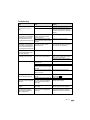 7
7
-
 8
8
-
 9
9
-
 10
10
-
 11
11
-
 12
12
-
 13
13
-
 14
14
-
 15
15
-
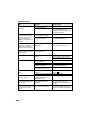 16
16
-
 17
17
-
 18
18
-
 19
19
-
 20
20
-
 21
21
-
 22
22


DEXAPLAN VT 623 Instrukcja obsługi
- Typ
- Instrukcja obsługi
- Ten podręcznik jest również odpowiedni dla
w innych językach
- English: DEXAPLAN VT 623 User manual
Powiązane dokumenty
Inne dokumenty
-
Commax DP-RS Instrukcja obsługi
-
Abus TVAC80020B instrukcja
-
Yamaha DVX-S60 Instrukcja obsługi
-
 Anjielo Smart 2.4G Wireless Video Intercom manual Instrukcja obsługi
-
Yamaha AVX-S80 Instrukcja obsługi
-
Yamaha DVR-S200 Instrukcja obsługi
-
Yamaha NX-S100S Instrukcja obsługi
-
-
-
Yamaha RXV363-B - Home Theater Receiver Instrukcja obsługi
