Yamaha YSP-4000 Instrukcja obsługi
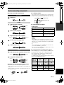
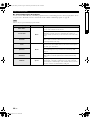
- Kategoria
- Dodatkowy sprzęt muzyczny
- Typ
- Instrukcja obsługi

YAMAHA ELECTRONICS CORPORATION, USA
6660 ORANGETHORPE AVE., BUENA PARK, CALIF. 90620, U.S.A.
YAMAHA CANADA MUSIC LTD.
135 MILNER AVE., SCARBOROUGH, ONTARIO M1S 3R1, CANADA
YAMAHA ELECTRONIK EUROPA G.m.b.H.
SIEMENSSTR. 22-34, 25462 RELLINGEN BEI HAMBURG, GERMANY
YAMAHA ELECTRONIQUE FRANCE S.A.
RUE AMBROISE CROIZAT BP70 CROISSY-BEAUBOURG 77312 MARNE-LA-VALLEE CEDEX02, FRANCE
YAMAHA ELECTRONICS (UK) LTD.
YAMAHA HOUSE, 200 RICKMANSWORTH ROAD WATFORD, HERTS WD18 7GQ, ENGLAND
YAMAHA SCANDINAVIA A.B.
J A WETTERGRENS GATA 1, BOX 30053, 400 43 VÄSTRA FRÖLUNDA, SWEDEN
YAMAHA MUSIC AUSTRALIA PTY, LTD.
17-33 MARKET ST., SOUTH MELBOURNE, 3205 VIC., AUSTRALIA
©
2007 All rights reserved.
YSP-4000
Printed in Malaysia WK94290
YSP-4000
Digital Sound Projector
TM
OWNER’S MANUAL
UA
00cv_YSP-4000_UA.fm Page 1 Thursday, September 20, 2007 10:08 AM

IMPORTANT SAFETY INSTRUCTIONS
i En
■ Explanation of Graphical Symbols
The lightning flash with arrowhead symbol,
within an equilateral triangle, is intended to
alert you to the presence of uninsulated
“dangerous voltage” within the product’s
enclosure that may be of sufficient magnitude
to constitute a risk of electric shock to
persons.
The exclamation point within an equilateral
triangle is intended to alert you to the
presence of important operating and
maintenance (servicing) instructions in the
literature accompanying the appliance.
1
Read these instructions.
2 Keep these instructions.
3 Heed all warnings.
4 Follow all instructions.
5 Do not use this apparatus near water.
6 Clean only with dry cloth.
7 Do not block any ventilation openings. Install in accordance with
the manufacturer’s instructions.
8 Do not install near any heat sources such as radiators, heat
registers, stoves, or other apparatus (including amplifiers) that
produce heat.
9 Do not defeat the safety purpose of the polarized or grounding-
type plug. A polarized plug has two blades with one wider than
the other. A grounding type plug has two blades and a third
grounding prong. The wide
blade or the third prong are provided for your safety. If the
provided plug does not fit into your outlet, consult an electrician
for replacement of the obsolete outlet.
10 Protect the power cord from being walked on or pinched
particularly at plugs, convenience receptacles, and the point
where they exit from the apparatus.
11 Only use attachments/accessories specified by the manufacturer.
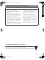
12 Use only with the cart, stand, tripod, bracket,
or table specified by the manufacturer, or
sold with the apparatus. When a cart is used,
use caution when moving the cart/apparatus
combination to avoid injury from tip-over.
13 Unplug this apparatus during lightning
storms or when unused for long periods of time.
14 Refer all servicing to qualified service personnel. Servicing is
required when the apparatus has been damaged in any way, such
as power supply cable or plug is damaged, liquid has been spilled
or objects have fallen into the apparatus, the apparatus has been
exposed to rain or moisture, does not operate normally, or has
been dropped.
IMPORTANT SAFETY INSTRUCTIONS
CAUTION
CAUTION: TO REDUCE THE RISK OF
ELECTRIC SHOCK, DO NOT REMOVE
COVER (OR BACK). NO USER-SERVICEABLE
PARTS INSIDE. REFER SERVICING TO
QUALIFIED SERVICE PERSONNEL.
RISK OF ELECTRIC SHOCK
DO NOT OPEN
01EN_YSP-4000_UA.book Page i Wednesday, December 26, 2007 3:00 PM
Black process 45.0° 240.0 LPI

IMPORTANT SAFETY INSTRUCTIONS
ii En
FCC INFORMATION (for US customers)
1. IMPORTANT NOTICE: DO NOT MODIFY THIS UNIT!
This product, when installed as indicated in the instructions
contained in this manual, meets FCC requirements.
Modifications not expressly approved by Yamaha may void
your authority, granted by the FCC, to use the product.
2. IMPORTANT:
When connecting this product to accessories and/or another
product use only high quality shielded cables. Cable/s supplied
with this product MUST be used. Follow all installation
instructions. Failure to follow instructions could void your FCC
authorization to use this product in the USA.
3. NOTE:
This product has been tested and found to comply with the
requirements listed in FCC Regulations, Part 15 for Class “B”
digital devices. Compliance with these requirements provides a
reasonable level of assurance that your use of this product in a
residential environment will not result in harmful interference
with other electronic devices.
This equipment generates/uses radio frequencies and, if not
installed and used according to the instructions found in the
users manual, may cause interference harmful to the operation
of other electronic devices.
Compliance with FCC regulations does not guarantee that
interference will not occur in all installations. If this product is
found to be the source of interference, which can be determined
by turning the unit “OFF” and “ON”, please try to eliminate the
problem by using one of the following measures:
Relocate either this product or the device that is being affected
by the interference.
Utilize power outlets that are on different branch (circuit
breaker or fuse) circuits or install AC line filter/s.
In the case of radio or TV interference, relocate/reorient the
antenna. If the antenna lead-in is 300 ohm ribbon lead, change
the lead-in to coaxial type cable.
If these corrective measures do not produce satisfactory results,
please contact the local retailer authorized to distribute this type
of product. If you can not locate the appropriate retailer, please
contact Yamaha Electronics Corp., U.S.A. 6660 Orangethorpe
Ave, Buena Park, CA 90620.
The above statements apply ONLY to those products distributed
by Yamaha Corporation of America or its subsidiaries.
We Want You Listening For A Lifetime
Yamaha and the Electronic Industries Association’s Consumer Electronics Group want you to get the most out of your
equipment by playing it at a safe level. One that lets the sound come through loud and clear without annoying
blaring or distortion – and, most importantly, without affecting your sensitive hearing.
Since hearing damage from loud sounds is often undetectable until it is too late, Yamaha and the Electronic Industries
Association’s Consumer Electronics Group recommend you to avoid prolonged exposure from excessive volume levels.
01EN_YSP-4000_UA.book Page ii Wednesday, December 26, 2007 3:00 PM
Black process 45.0° 240.0 LPI

CAUTION: READ THIS BEFORE OPERATING THIS UNIT.
iii En
1
To assure the finest performance, please read this manual
carefully. Keep it in a safe place for future reference.
2
Install this sound system in a well ventilated, cool, dry, clean place with
at least 5 cm (2 in) of space above (or below) this unit – away from
direct sunlight, heat sources, vibration, dust, moisture, and/or cold.
3 Locate this unit away from other electrical appliances, motors, or
transformers to avoid humming sounds.
4 Do not expose this unit to sudden temperature changes from cold
to hot, and do not locate this unit in an environment with high
humidity (i.e. a room with a humidifier) to prevent condensation
inside this unit, which may cause an electrical shock, fire,
damage to this unit, and/or personal injury.
5 Avoid installing this unit where foreign object may fall onto this
unit and/or this unit may be exposed to liquid dripping or
splashing. On the top of this unit, do not place:
– Other components, as they may cause damage and/or
discoloration on the surface of this unit.
– Burning objects (i.e. candles), as they may cause fire, damage
to this unit, and/or personal injury.
– Containers with liquid in them, as they may fall and liquid may
cause electrical shock to the user and/or damage to this unit.
6 Do not cover this unit with a newspaper, tablecloth, curtain, etc.
in order not to obstruct heat radiation. If the temperature inside
this unit rises, it may cause fire, damage to this unit, and/or
personal injury.
7 Do not plug in this unit to a wall outlet until all connections are
complete.
8 Do not operate this unit upside-down. It may overheat, possibly
causing damage.
9 Do not use force on switches, knobs and/or cords.
10 When disconnecting the power supply cable from the wall outlet,
grasp the plug; do not pull the cable.
11 Do not clean this unit with chemical solvents; this might damage
the finish. Use a clean, dry cloth.
12 Only voltage specified on this unit must be used. Using this unit
with a higher voltage than specified is dangerous and may cause
fire, damage to this unit, and/or personal injury. Yamaha will not
be held responsible for any damage resulting from use of this unit
with a voltage other than specified.
13 To prevent damage by lightning, keep the power supply cable
disconnected from a wall outlet or this unit during a lightning
storm.
14 Do not attempt to modify or fix this unit. Contact qualified
Yamaha service personnel when any service is needed.
The cabinet should never be opened for any reasons.
15 When not planning to use this unit for long periods of time (i.e.
vacation), disconnect the power supply cable from the wall
outlet.
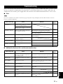
16 Be sure to read the “Troubleshooting” section on common
operating errors before concluding that this unit is faulty.
17 Before moving this unit, press STANDBY/ON to set this unit in
standby mode, and disconnect the power supply cable from the
wall outlet.
18 Condensation will form when the surrounding temperature
changes suddenly. Disconnect the power supply cable from the
outlet, then leave the unit alone.
19 When using the unit for a long time, the unit may become warm.
Turn the power off, then leave the unit alone for cooling.
20 Install this unit near the AC outlet and where the AC power plug
can be reached easily.
21 The batteries shall not be exposed to excessive heat such as
sunshine, fire or the like.
Caution: Read this before operating this unit.
WARNING
TO REDUCE THE RISK OF FIRE OR ELECTRIC SHOCK, DO
NOT EXPOSE THIS UNIT TO RAIN OR MOISTURE.
WARNING
THE POWER SUPPLY CABLE OF THIS UNIT MUST BE
CONNECTED TO THE MAIN SOCKET OUTLET VIA A
PROTECTIVE EARTHING CONNECTION.
This unit is not disconnected from the AC power source as long as
it is connected to the AC wall outlet, even if this unit itself is
turned off by STANDBY/ON. This state is called the standby
mode. In this state, this unit is designed to consume a very small
quantity of power.
IMPORTANT
Please record the serial number of this unit in the space below.
MODEL:
Serial No.:
The serial number is located on the rear of the unit. Retain this
Owner’s Manual in a safe place for future reference.
FOR CANADIAN CUSTOMERS
To prevent electric shock, match wide blade of plug to wide slot
and fully insert.
This Class B digital apparatus complies with Canadian ICES-003.
FOR U.K. CUSTOMERS
If the socket outlets in the home are not suitable for the plug
supplied with this appliance, it should be cut off and an
appropriate 3-pin plug fitted. For details, refer to the instructions
described below.
Note
The plug severed from the mains lead must be destroyed, as a plug with
a bared flexible cord is hazardous if engaged in a live socket outlet.
IMPORTANT
THE WIRES IN THIS MAINS LEAD ARE COLOURED IN
ACCORDANCE WITH THE FOLLOWING CODE:
GREEN-AND-YELLOW: EARTH
BLUE: NEUTRAL
BROWN: LIVE
As the colours of the wires in the mains lead of this apparatus may
not correspond with the coloured markings identifying the
terminals in your plug, proceed as follows:
The wire which is coloured GREEN-AND-YELLOW must be
connected to the terminal in the plug which is marked by the letter
“E” or the safety earth symbol or coloured GREEN or GREEN-
AND-YELLOW.
The wire which is coloured BLUE must be connected to the
terminal marked with the letter “N” or coloured BLACK.
The wire which is coloured BROWN must be connected to the
terminal marked with the letter “L” or coloured RED.
CAUTION
Danger of explosion if battery is incorrectly replaced. Replace
only with the same or equivalent type.
CAUTION
Use of controls or adjustments or performance of procedures other
than those specified herein may result in hazardous radiation
exposure.
01EN_YSP-4000_UA.book Page iii Wednesday, December 26, 2007 3:00 PM
Black process 45.0° 240.0 LPI

PREPARATIONINTRODUCTION
BASIC
OPERATION
ADVANCED
OPERATION
ADDITIONAL
INFORMATION
SETUP
English
1 En
Overview ................................................................. 2
Features .................................................................. 3
Using this manual .................................................. 5
Supplied accessories .............................................. 6
Controls and functions .......................................... 7
Front panel ................................................................ 7
Front panel display ................................................... 8
Rear panel ................................................................. 9
Remote control (Europe, Australia, Asia,
and Korea models) .............................................. 11
Remote control (U.S.A. and Canada models) ......... 14
Installation ............................................................ 17
Before installing this unit ........................................ 17
Installing this unit ................................................... 17
Connections .......................................................... 20
Before connecting components ............................... 21
Connections using HDMI cables ............................ 22
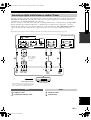
Connecting a TV ..................................................... 23
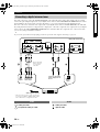
Connecting a DVD player/recorder ........................ 24
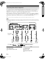
Connecting a digital satellite tuner or a cable TV tuner
25
Connecting a digital airwave tuner ......................... 26
Connecting a portable audio player ........................ 27
Connecting other external components .................. 28
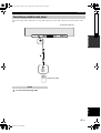
Connecting a subwoofer ......................................... 29
Connecting the FM antenna .................................... 30
About the RS-232C/IR-OUT/IR IN terminals ........ 30
Connecting the AC power supply cable ................. 31
Getting started ..................................................... 32
Installing batteries in the remote control ................ 32
Operation range of the remote control .................... 32
Turning on this unit or
setting it to the standby mode ............................. 33
Using SET MENU ................................................ 34
Displaying the OSD (on-screen display) ................ 34
The flow chart of SET MENU ................................ 35
Changing OSD language ..................................... 36
AUTO SETUP (IntelliBeam) .............................. 37
The flow chart of AUTO SETUP ........................... 37
Installing the IntelliBeam microphone ................... 38
Using AUTO SETUP (IntelliBeam) ....................... 39
Using the system memory ................................... 44
Convenient usage of the system memory ............... 44
Saving settings ........................................................ 44
Loading settings ...................................................... 45
Playback ............................................................... 47
Selecting the input source ....................................... 47
Playing back sources ............................................... 48
Adjusting the volume .............................................. 49
FM tuning ............................................................. 50
FM controls and functions ...................................... 50
Automatic tuning .................................................... 51
Manual tuning ......................................................... 51
Automatic preset tuning .......................................... 52
Manual preset tuning .............................................. 53
Selecting a preset station ........................................ 54
Displaying the Radio Data System information
(Europe model only) ........................................... 54
Enjoying surround sound ....................................56
5 Beam .................................................................... 56
Stereo plus 3 Beam ................................................. 57
3 Beam .................................................................... 57
My Surround ........................................................... 57
Enjoying 2-channel sources
in surround sound ............................................... 59
Enjoying TV in surround sound ............................. 60
Adjusting surround mode parameters ..................... 61
Enjoying stereo sound ..........................................62
2-channel stereo playback ....................................... 62
5-channel stereo playback ....................................... 62
Playing back sound clearly (My Beam) ..............63
Using auto-adjust function ...................................... 63
Using manual-adjust function ................................. 64
Using sound field programs .................................65
CINEMA DSP programs ........................................ 67
Using the music enhancer ....................................70
Using the volume mode
(Night listening enhancer/
TV volume equal mode) ...................................71
Using the sleep timer ............................................72
Displaying the input source information ............74
Using the HDMI control feature .........................75
MANUAL SETUP ................................................76
Using MANUAL SETUP ....................................... 77
BEAM MENU ........................................................ 78
SOUND MENU ...................................................... 82
INPUT MENU ........................................................ 84
DISPLAY MENU ................................................... 88
Adjusting the audio balance ................................90
Using the test tone .................................................. 90
Using the audio output being played back .............. 91
Selecting the input mode ......................................93
Adjusting the system parameters .......................94
Using the system parameters .................................. 94
Setting the MEMORY PROTECT ......................... 95
Setting the MAX VOLUME ................................... 96
Setting the TURN ON VOLUME .......................... 96
Setting the MONITOR CHECK ............................. 97
Setting the DEMO MODE ..................................... 98
Setting the PANEL INPUT KEY ........................... 99
Disabling the front panel keys .............................. 100
Setting the FACTORY PRESET .......................... 101
Remote control features .....................................103
Setting remote control codes ................................ 103
Controlling other components .............................. 104
Using the TV macro ............................................. 107
Troubleshooting ..................................................109
Glossary ...............................................................113
Index ....................................................................115
Specifications ......................................................116
List of remote control codes...........................................i
Contents
INTRODUCTION
PREPARATION
SETUP
BASIC OPERATION
ADVANCED OPERATION
ADDITIONAL INFORMATION
01EN_YSP-4000_UA.book Page 1 Wednesday, December 26, 2007 3:00 PM
Black process 45.0° 240.0 LPI

Overview
2 En
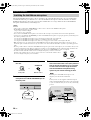
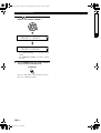
It is generally accepted that in order to fully enjoy the benefits of surround sound at home, you must endure the agony of
wiring and installing a great number of speakers in the hope that your listening room will give you the same kind of
surround sound experience as your local movie theater.
Yamaha YSP-4000 Digital Sound Projector challenges this preconception that complicated speaker setup and
troublesome wiring go hand-in-hand with the enjoyment of multi-channel surround sound.
This slimline unit does away with the need for complicated wiring and installation worries, leaving you with a unit that is
not only easy to set up, but is also capable of reproducing the kind of powerful surround sound you have been waiting for
from its built-in 2 woofers and 40 full-range small speakers.
You can fine-tune the parameters of this unit to adjust the delay time for separate sound beams, resulting in highly
directional sound that comes in on the listening position from all directions.
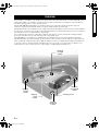
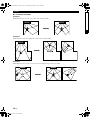
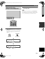
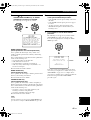
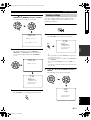
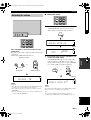
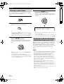
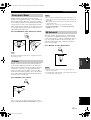
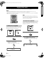
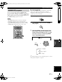
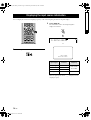
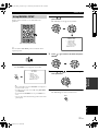
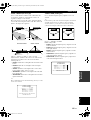
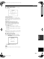
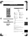
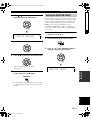
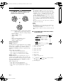
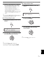
The YSP-4000 projects sound beams containing surround sound information for the front right (R), front left (L),
surround right (SR), and surround left (SL) speaker positions, which are reflected off the walls of your listening room
before reaching the actual listening position. With the addition of center (C) sound beams, this Digital Sound Projector
creates true-to-life 5.1-channel surround sound that makes you feel as if there are actual speakers around the room.
Sit back and enjoy the real sound experience of this simple, yet stylish Digital Sound Projector.
Overview
SL
SR
R
L
C
Listening position
Imaginary
surround left
speaker
Imaginary
surround right
speaker
Imaginary
front left
speaker
Imaginary
front right
speaker
Imaginary
center
speaker
01EN_YSP-4000_UA.book Page 2 Wednesday, December 26, 2007 3:00 PM
Black process 45.0° 240.0 LPI

Features
3 En
INTRODUCTION
English
Digital Sound Projector™
The Digital Sound Projector technology allows one slim
unit to control and steer multiple channels of sound to
generate multi-channel surround sound, thus eliminates
the need for satellite loudspeakers and cabling normally
associated with conventional surround sound systems.
This unit also employs the beam modes that let you enjoy
the surround sound (5 Beam, Stereo plus 3 Beam, 3 Beam,
and My Surround), 2-channel and 5-channel stereo
playback, and My Beam.
My Surround
In addition to the above mentioned beam modes, this unit
is equipped with My Surround beam mode that allows you
to enjoy surround system even in a small listening area.
My Surround is a function integrated and optimized with
DiMAGIC’s Euphony technology and Yamaha’s Beam
reproduction system.
My Beam
This unit employs My Beam that ensures a clear sound in
a noisy environment. You can adjust the beam angle
manually or automatically using the supplied remote
control to the maximum of 45°, rightward and leftward.
Cinema DSP
This unit employs the Cinema DSP technology developed
by Yamaha Electronics Corp. that lets you experience
movies at home with all the original dramatic sound
impact.
HDMI™ (High-Definition Multimedia Interface)
◆ HDMI interface for standard, enhanced, or high-definition
video (including 1080p video signal transmission) as well as
multi-channel digital audio based on HDCP
◆ Simple and easy connections with HDMI supported external
components
◆ Functional link with an HDMI control-compatible TV
◆ Analog video up-scaling from 480i (NTSC)/576i (PAL) or
480p (NTSC)/576p (PAL) to 720p or 1080i
Versatile Remote Control
The supplied remote control comes with preset remote
control codes used to control the DVD player, VCR, cable
TV tuner, and digital satellite tuner connected to this unit.
In addition, the remote control is equipped with the macro
capability that enables a series of operations with the press
of a single button.
AUTO SETUP (IntelliBeam)
This unit employs the automatic sound beam and acoustic
optimization technology with the aid of the supplied
IntelliBeam microphone. You can avoid troublesome
listening-based speaker setup and achieve highly accurate
sound beam adjustments that best match your listening
environment.
Compatibility with the Newest Technologies
This unit employs decoders compatible with Dolby
Digital, DTS, Dolby Pro Logic, Dolby Pro Logic II, DTS
Neo:6, Music Enhancer, and Neural Surround.
◆ Dolby Digital
This is the standard audio signal format used on various
digital media such as DVD, Blu-ray, and HD DVD. This
surround technology delivers high-quality digital audio for up
to 5.1 discrete channels to produce a directional and more
realistic effect.
◆ DTS
This is the standard audio signal format used on various
digital media such as DVD, Blu-ray, and HD DVD. This
surround technology delivers high-quality digital audio for up
to 5.1 discrete channels to produce a directional and more
realistic effect.
◆ Dolby Pro Logic
This sophisticated, matrix decoding technology up-converts
any 2-channel source audio to a 5.1-channel full bandwidth
playback, resulting in a surround sound experience.
◆ Dolby Pro Logic II
This is a redesigned version of Dolby Pro Logic that employs
2 stereo surround channels, a subwoofer, and a greatly
enhanced steering logic. This improved technology provides
an exceptionally stable sound field that simulates 5.1 to a
much greater degree than the original Dolby Pro Logic.
◆ DTS Neo:6
This technology decodes the conventional 2-channel sources
for 6-channel playback, enabling playback with the full-range
channels with higher separation. Music mode and Cinema
mode are available to play back music and movie sources
respectively.
◆ Music Enhancer to improve the sound quality of compression
artifacts such as the MP3 format.
◆ Neural Surround decoder (U.S.A and Canada models only)
Sophisticated FM tuner
◆ 40-station random and direct preset tuning
◆ Automatic preset tuning
◆ Radio Data System capability (Europe model only)
XM™ Satellite Radio
(U.S.A. and Canada models only)
◆ XM Satellite Radio tuning capability (using the XM Mini-
Tuner Dock, and Antenna sold separately by XM Satellite
Radio)
◆ Neural Surround decoder to play back the XM HD content of
XM Satellite Radio broadcasts in multi-channels, resulting in
a full surround sound experience
◆ XM Satellite Radio information displaying capability
iPod™ Controlling Capability
(U.S.A., Canada, and Australia models only)
◆ DOCK terminal to connect a Yamaha iPod universal dock
(such as the YDS-10, sold separately), which supports iPod
(Click and Wheel), iPod nano, and iPod mini
◆ Playback information displaying capability
◆ Battery charging capability
Features
01EN_YSP-4000_UA.book Page 3 Wednesday, December 26, 2007 3:00 PM
Black process 45.0° 240.0 LPI

Features
4 En
The “ ” logo and “IntelliBeam” are trademarks of
YAMAHA CORPORATION.
The “ ” logo and “Cinema DSP” are registered
trademarks of YAMAHA CORPORATION.
Manufactured under license from Dolby Laboratories.
“Dolby”, “Pro Logic”, and the double-D symbol are trademarks
of Dolby Laboratories.
“DTS” and “Neo:6” are registered trademarks of DTS, Inc.
“HDMI”, the “HDMI” logo and “High-Definition Multimedia
Interface” are trademarks or registered trademarks of HDMI
Licensing LLC.
Manufactured under license from 1 Ltd. Worldwide patents
applied for.
The “ ” logo and “Digital Sound Projector
™
” are trademarks
of 1 Ltd.
TruBass, SRS and the “ ” symbol are registered trademarks
of SRS Labs, Inc. TruBass technology is incorporated under
license from SRS Labs, Inc.
™
is a trademark of DiMAGIC Co., Ltd.
01EN_YSP-4000_UA.book Page 4 Wednesday, December 26, 2007 3:00 PM
Black process 45.0° 240.0 LPI

Using this manual
5 En
INTRODUCTION
English
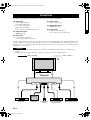
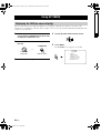
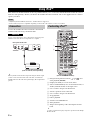
• This manual describes how to connect and operate this unit. For details regarding the operation of external components, refer to the
supplied owner’s manual for each component.
• Operations in this manual use keys on the supplied remote control of this unit unless otherwise specified.
• y indicates a tip for your operation.
• This manual is printed prior to production. Designs and specifications are subject to change in part as a result of improvements, etc. In
case of differences between the manual and the product, the product has priority.
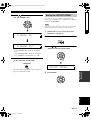
1 Install this unit in your listening room.
See “Installation” on page 17.
2 Connect this unit to your TV and other external components.
See “Connections” on page 20.
3 Prepare the remote control and turn on the power of this unit.
See “Getting started” on page 32.
4 Run AUTO SETUP.
See “AUTO SETUP (IntelliBeam)” on page 37.
5 Play back a source.
See “Playback” on page 47.
6 Change the beam modes and/or CINEMA DSP settings.
See “Enjoying surround sound” on page 56.
7 Run MANUAL SETUP to fine-tune settings and/or set remote control codes.
See “MANUAL SETUP” on page 76 and “Remote control features” on page 103.
Using this manual
Notes
If you want to make additional settings
and adjustments
01EN_YSP-4000_UA.book Page 5 Wednesday, December 26, 2007 3:00 PM
Black process 45.0° 240.0 LPI

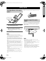
Supplied accessories
6 En
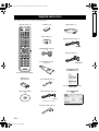
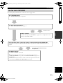
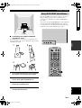
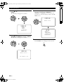
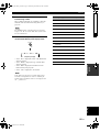
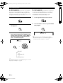
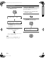
Check that you have received all of the following parts.
Supplied accessories
STEREO MY SUR.
MY BEAM
PRESET/TUNE
MEMORYSEARCH
SLEEP
INPUTMODE
ENHANCER MENU
RETURNDISPLAY
TV VOL
VOLUME
MUTE
CH LEVEL TEST
TV INPUT TV MUTE
ENTER
SUR. DECODE
OFF
CODE SET
SPORTS
5BEAM ST+3BEAM 3BEAM
MUSIC MOVIE
VOL MODE
AUTO
SETUP
CATFM/XM
MACRO
TV
INPUT1
YSP
TV/AV
CH
ENTRY
CAT/
A-E
4
6
321
AUX1 AUX2
STB
TV
DVD
AUX3
TV
POWERPOWERSTANDBY/ON
DOCK
+10
0
78
9
5
AV
Remote control (×1)
Batteries (×2)
(AA, R6, UM-3)
OSD* video pin cable (×1)
IntelliBeam microphone
(×1)
Fasteners (×4)
Audio pin cable (×1)
Digital audio pin cable (×1)
Optical cable (×1)
Cable clamp (×1)
Cardboard microphone
stand (×1)
(Orange)
(White/Red)
(Yellow)
Indoor FM antenna (×1)
(U.S.A. and Canada models)
Demonstration DVD
(×1)
REFERENCE GUIDE
(iPod/XM Radio) (×1)
QUICK REFERENCE
GUIDE
(U.S.A., Canada, and Australia
models only)
* The number of provided languages
varies depending on the model.
AC power supply cable (×1)
* OSD: On-Screen Display
01EN_YSP-4000_UA.book Page 6 Wednesday, December 26, 2007 3:00 PM
Black process 45.0° 240.0 LPI

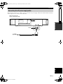
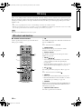
Controls and functions
7 En
INTRODUCTION
English
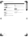
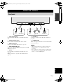
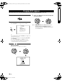
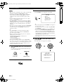
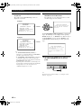
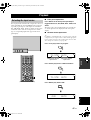
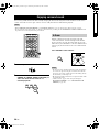
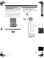
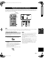
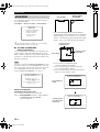
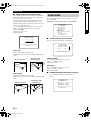
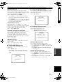
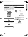
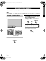
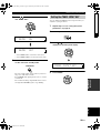
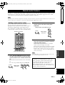
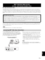
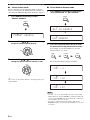
1 Front panel display
Shows information about the operational status of this
unit.
2 Remote control sensor
Receives infrared signals from the remote control.
3 AUX 3 input jack
Connect your portable audio player (see page 27).
4 INTELLIBEAM MIC jack
Connect the supplied IntelliBeam microphone for AUTO
SETUP (see page 38).
5 INPUT
Press repeatedly to switch between input sources (see
page 47).
Outputs a test tone to experience the sound beam (see
page 98).
6 VOLUME +/–
Controls the volume level of all audio channels (see
page 49).
7 STANDBY/ON
Turns on the power of this unit or sets it to the standby
mode (see page 33).
• When you turn on this unit, you will hear a click sound
followed by the 4 to 5-second interval before sound
reproducing.
• In the standby mode, this unit consumes a small amount of
power in order to receive infrared signals from the remote
control or to search for HDMI signals.
Controls and functions
Front panel
INPUT VOLUME STANDBY/ON
+
INTELLIBEAM MIC
AUX 3
INPUT VOLUME STANDBY/ON
+
INTELLIBEAM MIC
AUX 3
4
2
3 5 6 7
1
Notes
01EN_YSP-4000_UA.book Page 7 Wednesday, December 26, 2007 3:00 PM
Black process 45.0° 240.0 LPI

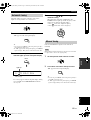
Controls and functions
8 En
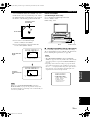
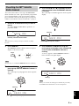
1 HDMI indicator
Lights up when the signal of the selected input source is
input at the HDMI IN jack(s).
2 TUNER indicators
FM: Light up when this unit is receiving an FM broadcast.
XM: MEMORY flashes during the XM preset operation
(U.S.A. and Canada models only).
3 CINEMA DSP indicator
Lights up when a sound field program is selected (see
page 67).
4 PCM indicator
Lights up when this unit is reproducing PCM (Pulse Code
Modulation) digital audio signals.
5 Decoder indicators
Light up when the corresponding decoder operates
(see page 58).
The neural decoder is available for the U.S.A. and Canada models
only.
6 ENHANCER indicator
Lights up when the Music Enhancer is selected (see
page 70).
7 Volume level indicator
Displays the current volume level.
8 DOCK indicator
(U.S.A., Canada, and Australia models only)
Lights up when your iPod (Click and Wheel), iPod nano,
or iPod mini is connected to this unit via the DOCK
terminal on this unit.
9 SRS TruBass indicator
Lights up when TruBass is turned on (see page 84).
0 EQUAL indicator
Lights up when the TV volume equal mode is selected
(see page 71).
A NIGHT indicator
Lights up when one of the night listening enhancers is
selected (see page 71).
B SLEEP indicator
Lights up when the sleep timer is set (see page 72).
C Radio Data System indicators
(Europe model only)
Show the current Radio Data System status.
D XM indicator
(U.S.A. and Canada models only)
Lights up when XM is selected as the input source.
E Multi-information display
Shows information with alphanumeric characters when
you adjust the parameters of this unit.
F Input channel indicators
Show information when you adjust the parameters of this
unit. The channel component of the current digital input
signal is displayed (see page 58).
y
You can adjust the brightness and display setting of the front
panel display using the F.DISPLAY SET parameter in MANUAL
SETUP (see page 88).
Front panel display
1
89
0
23
4
67
5
AB C D
EF
Note
01EN_YSP-4000_UA.book Page 8 Wednesday, December 26, 2007 3:00 PM
Black process 45.0° 240.0 LPI

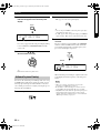
Controls and functions
9 En
INTRODUCTION
English
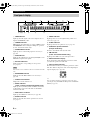
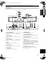
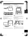
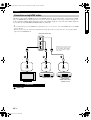
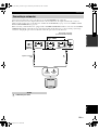
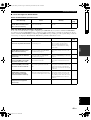
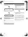
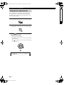
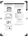
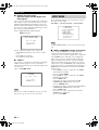
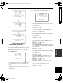
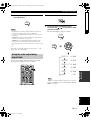
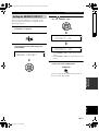
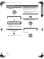
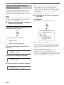
The illustration below shows the rear panel of the U.S.A. and Canada models.
1 AUX 1 HDMI IN jack
Connect your digital satellite tuner, cable TV tuner, digital
air wave tuner, or game console via an HDMI connection
(see page 22).
2 DVD HDMI IN jack
Connect your DVD player via an HDMI connection (see
page 22).
3 HDMI OUT jack
Connect to the HDMI IN jack on your HDMI component
such as a TV or a projector connected to this unit (see
page 22).
4 AC IN
Connect the supplied AC power supply cable
(see page 31).
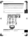
5 IR-OUT terminal
This is a control expansion terminal for commercial use
only (see page 30).
6 ANTENNA jack
Connect the FM antenna (see page 30).
7 SUBWOOFER jack
Connect your subwoofer (see page 29).
8 TV/STB AUDIO IN jacks
Connect your TV, digital satellite tuner, or cable TV tuner
via an analog connection (see pages 23 and 25).
9 AUX 1 AUDIO IN jacks
Connect an external component via an analog connection
(see page 24).
0 DOCK terminal
(U.S.A., Canada, and Australia models only)
Connect the Yamaha iPod universal dock (such as YDS-
10, sold separately) (see page 2 in the Reference Guide).
A DVD COAXIAL DIGITAL IN jack
Connect your DVD player via a coaxial digital connection
(see page 24).
B AUX 2 COAXIAL DIGITAL IN jack
Connect an external component via a coaxial digital
connection (see page 28).
Rear panel
IR-OUT
AUX 1
DVD
IN
OUT
HDMI
RS-232C
IR INXM
OPTICAL
COAXIAL
DVD AUX 2
AUX 1TV/STB
DIGITAL INDOCK
AUX 1STB
ANTENNA
DVD/AUX 2 AUX 1 TV/STB
AUDIO IN
VIDEO IN
SYSTEM
CONNECTOR
SUBWOOFER
COMPONENTCOMPONENTCOMPONENT
VIDEO OUT
FM75
UNBAL.
IR-OUT
I JHGFMLKON
60978 EDCBA
1
2
3
4
5
(U.S.A. and Canada models)
01EN_YSP-4000_UA.book Page 9 Wednesday, December 26, 2007 3:00 PM
Black process 45.0° 240.0 LPI

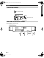
Controls and functions
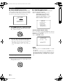
10 En
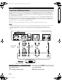
C XM antenna jack
(U.S.A and Canada models only)
Connect your XM Mini-Tuner Dock (sold separately)
(see page 5 in the Reference Guide).
D IR IN terminal
This is a control expansion terminal for commercial use
only (see page 30).
E RS-232C terminal
This is a control expansion terminal for commercial use
only (see page 30).
F SYSTEM CONNECTOR terminal
(U.S.A. and Canada models only)
Use to connect a Yamaha subwoofer equipped with a
SYSTEM CONNECTOR terminal to this unit.
G VIDEO OUT jack
Connect to the video input jack of your TV via a
composite analog video connection to display the OSD of
this unit (see page 23).
H COMPONENT VIDEO OUT jacks
Connect to the video input jacks of your TV via a
component analog video connection to display the OSD of
this unit (see page 23).
I STB VIDEO IN jacks
Connect a digital satellite tuner or a cable TV tuner via a
composite analog video connection (see pages 25 to 26).
J STB COMPONENT VIDEO IN jacks
Connect a digital satellite tuner or a cable TV tuner via a
component analog video connection (see pages 25 to 26).
K DVD/AUX 2 VIDEO IN jacks
Connect a DVD player/recorder or an external component
via a composite analog video connection
(see pages 24 and 28).
L DVD/AUX 2 COMPONENT VIDEO IN jacks
Connect a DVD player/recorder or an external component
via a component analog video connection (see pages 24
and 28).
M AUX 1 VIDEO IN jacks
Connect an external component via a composite analog
video connection (see page 28).
N TV/STB OPTICAL DIGITAL IN jack
Connect your TV, digital satellite tuner, or cable TV tuner
via an optical digital connection (see pages 23 and 25).
O AUX 1 OPTICAL DIGITAL IN jack
Connect an external component via an optical digital
connection (see page 28).
01EN_YSP-4000_UA.book Page 10 Wednesday, December 26, 2007 3:00 PM
Black process 45.0° 240.0 LPI

Controls and functions
11 En
INTRODUCTION
English
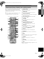
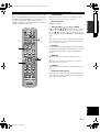
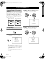
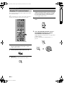
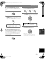
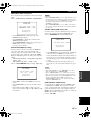
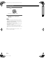
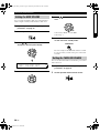
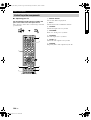
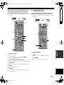
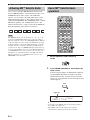
This section describes the functions of the remote control
used to control this unit. Some buttons marked with an
asterisk (*) share the common functions between the YSP
and TV/AV operation modes (S).
y
You can also control other components using the remote control
once you set the appropriate remote control codes. See
“Controlling other components” on page 104 for details.
1 Infrared window
Outputs infrared control signals. Aim this window at the
component you want to operate.
2 STANDBY/ON
Sets this system to the standby mode (see page 33).
3 Transmission indicator
Lights up when infrared control signals are being output.
4 Input selector buttons
Use to select an input source (DVD, AUX1, AUX2,
AUX3, STB, TV, or FM).
5 VOL MODE
Turns on or off the volume modes (see page 71).
6 AUTO SETUP
Enters the AUTO SETUP menu (see page 37).
7 CINEMA DSP program buttons
Select the CINEMA DSP programs (see page 65).
8 ENHANCER
Turns on or off the Music Enhancer (see page 70).
9 Cursor buttons / / / , ENTER
Select and adjust SET MENU items.
0 DISPLAY
Displays information on the selected input signal.
A VOLUME +/–
Increases or decreases the volume level of this unit (see
page 49).
B MUTE
Mutes the sound. Press again to restore the audio output to
the previous volume level (see page 49).
C TV INPUT
Toggles between the input sources on the TV (see
page 104).
D CH LEVEL
Adjusts the volume level of each channel (see page 91).
E TEST
Outputs a test tone when adjusting the output level of each
channel (see page 90).
Remote control (Europe, Australia, Asia, and Korea models)
STEREO
MY BEAM
PRESET/TUNE
MEMORYSEARCH
SLEEP
INPUTMODE
ENHANCER MENU
RETURNDISPLAY
TV VOL
VOLUME
MUTE
CH LEVEL TEST
TV INPUT TV MUTE
ENTER
SUR. DECODE
OFF
CODE SET
SPORTS
5BEAM ST+3BEAM 3BEAM
MUSIC MOVIE
VOL MODE
AUTO
SETUP
A-E
MACRO
TV
INPUT1
YSP
TV/AV
CH
ENTRY
A-E
4
6
321
AUX1 AUX2
STB
FM
TV
DVD
AUX3
TVAV
POWERPOWERSTANDBY/ON
+10
0
78
9
5
MY SUR.
1G
H
I
J
K
L
M
N
O
P
Q
R
S
t
U
V
W
2
3
4
5
6
7
8
9
0
A
B
C
D
E
F
*
*
*
*
*
*
*
*
*
*
*
01EN_YSP-4000_UA.book Page 11 Wednesday, December 26, 2007 3:00 PM
Black process 45.0° 240.0 LPI

Controls and functions
12 En
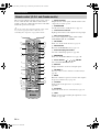
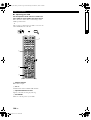
F DVD player/VCR control buttons
Control your DVD player or VCR (see pages 105 and
106).
G My Beam microphone
Collects the test tones from this unit when using the My
Beam auto-adjust function (see page 63).
H TV POWER
Turns on the power of your TV or sets it to the standby
mode (see page 104).
I AV POWER
Turns on the power of the selected component or sets it to
the standby mode (see pages 105 and 106).
J INPUT1
Switches the input source on your TV (see page 104).
K MACRO
Use to set the TV macro (see page 107).
L a /5
Switches the preset station number (1 to 8) when this unit
is receiving an FM broadcast (see page 54).
M A-E
Switches the preset station group (A to E) when this unit is
receiving an FM broadcast (see page 54).
N SLEEP
Sets the sleep timer (see page 72).
O INPUTMODE
Toggles between input modes (AUTO, DTS, and
ANALOG) (see page 93).
P Beam mode buttons
Change the beam mode settings (see pages 56, 62, and
63).
Q SUR. DECODE
Selects the surround mode for playback (see page 59).
R MENU
Displays the setup menu on your TV monitor (see
pages 39 and 77).
S Operation mode selector
Selects the operation mode of this unit. Select YSP when
operating this unit and select TV/AV when operating your
TV or other AV components.
T RETURN
Selects sleep timer settings or returns to the previous SET
MENU screen.
U TV VOL +/–
Adjusts the volume level of your TV (see page 104).
V CH +/–
Changes the channels of your TV, digital satellite tuner,
cable TV tuner, or VCR (see pages 104 and 106).
W TV MUTE, CODE SET
Mutes the audio output of your TV (see page 104).
Sets up remote control codes (see page 103).
The functions L and M are available only when the FM stations
are preset.
Note
01EN_YSP-4000_UA.book Page 12 Wednesday, December 26, 2007 3:00 PM
Black process 45.0° 240.0 LPI

Controls and functions
13 En
INTRODUCTION
English
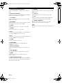
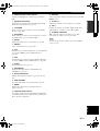
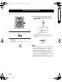
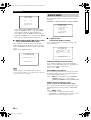
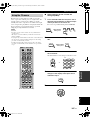
This section describes the functions of the remote control
used to control FM, Radio Data System, or iPod when the
TV/AV mode is selected with the operation mode selector
(7). Note that the Radio Data System controls are
available for Europe model only, and the iPod controls are
available for Australia model only.
1 PRESET/TUNE
FM: Switches between the preset search mode and the
frequency search mode (see pages 51 to 54).
2 Numeric buttons
FM: Enter numbers.
3 Cursor buttons / / / , ENTER
FM: Use ENTRY ( / ) to change the preset station
number (1 to 8) or frequency level (see pages 51 to 54).
Use A-E ( / ) to change the preset station group (A to
E) (see pages 53 and 54). Use ENTER to confirm the input
above.
y
These functions are also available when this unit is receiving the
Radio Data System (see page 54) or playing back your iPod (see
page 3 in the Reference Guide).
4 DISPLAY
Radio Data System and iPod: Displays information when
this unit is receiving the Radio Data System (see page 54)
or playing back your iPod (see page 2 in the Reference
Guide).
5 MEMORY
FM: Stores the preset stations (see pages 52 and 53).
y
This function is also available when this unit is receiving the
Radio Data System (see page 54).
6 SEARCH
FM: Switches between automatic and manual tuning (see
page 51).
7 Operation mode selector
Selects the operation mode of this unit. Select YSP when
operating this unit and select TV/AV when operating your
TV or other AV components.
4
6
321
+10
0
78
9
5
STEREO
MY BEAM
PRESET/TUNE
MEMORYSEARCH
SLEEP
INPUTMODE
ENHANCER MENU
RETURNDISPLAY
TV VOL
VOLUME
MUTE
CH LEVEL TEST
TV INPUT TV MUTE
OFF
CODE SET
SPORTS
5BEAM ST+3BEAM 3BEAM
MUSIC MOVIE
VOL MODE
AUTO
SETUP
A-E
MACRO
TV
INPUT1
YSP
TV/AV
CH
ENTRY
A-E
AUX1 AUX2
STB
FM
TV
DVD
AUX3
TVAV
POWERPOWERSTANDBY/ON
ENTER
SUR. DECODE
MY SUR.
1
2
3
4
5
6
7
01EN_YSP-4000_UA.book Page 13 Wednesday, December 26, 2007 3:00 PM
Black process 45.0° 240.0 LPI

Controls and functions
14 En
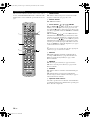
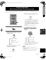
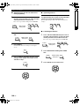
This section describes the functions of the remote control
used to control this unit. Some buttons marked with an
asterisk (*) share the common functions between the YSP
and TV/AV operation modes (S).
y
You can also control other components using the remote control
once you set the appropriate remote control codes. See
“Controlling other components” on page 104 for details.
1 Infrared window
Outputs infrared control signals. Aim this window at the
component you want to operate.
2 STANDBY/ON
Sets this system to the standby mode (see page 33).
3 Transmission indicator
Lights up when infrared control signals are being output.
4 Input selector buttons
Use to select an input source (DVD, AUX1, AUX2,
AUX3/DOCK, STB, TV, or FM/XM).
5 VOL MODE
Turns on or off the volume modes (see page 71).
6 AUTO SETUP
Enters the AUTO SETUP menu (see page 37).
7 Sound field program buttons
Select the sound field programs (see page 65).
8 ENHANCER
Turns on or off the Music Enhancer (see page 70).
9 Cursor buttons / / / , ENTER
Select and adjust SET MENU items.
0 DISPLAY
Displays information on the selected input signal.
A VOLUME +/–
Increases or decreases the volume level of this unit (see
page 49).
B MUTE
Mutes the sound. Press again to restore the audio output to
the previous volume level (see page 49).
C TV INPUT
Toggles between the input source on your TV (see
page 104).
D CH LEVEL
Adjusts the volume level of each channel (see page 91).
E TEST
Outputs a test tone when adjusting the output level of each
channel (see page 90).
Remote control (U.S.A. and Canada models)
STEREO
MY BEAM
PRESET/TUNE
MEMORYSEARCH
SLEEP
INPUTMODE
ENHANCER MENU
RETURNDISPLAY
TV VOL
VOLUME
MUTE
CH LEVEL TEST
TV INPUT TV MUTE
ENTER
OFF
CODE SET
SPORTS
5BEAM ST+3BEAM
MUSIC MOVIE
VOL MODE
AUTO
SETUP
CATFM/XM
MACRO
TV
INPUT1
YSP
TV/AV
CH
ENTRY
CAT/
A-E
4
6
321
AUX1 AUX2
STB
TV
DVD
AUX3
TV
POWERPOWERSTANDBY/ON
DOCK
+10
0
78
9
5
AV
MY SUR.
3BEAM
SUR. DECODE
1G
H
I
J
K
L
M
N
O
P
Q
R
S
t
U
V
W
2
3
4
5
6
7
8
9
0
A
B
C
D
E
F
*
*
*
*
*
*
*
*
*
*
*
01EN_YSP-4000_UA.book Page 14 Wednesday, December 26, 2007 3:00 PM
Black process 45.0° 240.0 LPI

Controls and functions
15 En
INTRODUCTION
English
F DVD player/VCR control buttons
Control your DVD player or VCR (see pages 105 and
106).
G My Beam microphone
Collects the test tones from this unit when using the My
Beam auto-adjust function (see page 63).
H TV POWER
Turns on the power of your TV or sets it to the standby
mode (see page 104).
I AV POWER
Turns on the power of the selected component or sets it to
the standby mode (see pages 105 and 106).
J INPUT1
Switches the input source on your TV (see page 104).
K MACRO
Use to set the TV macro (see page 107).
L a /5
Switches the preset station number (1 to 8) when this unit
is receiving an FM broadcast or XM channel (see
page 54).
M CAT
Switches the preset station group (A to E) when this unit is
receiving an FM broadcast or XM channel (see page 54).
N SLEEP
Sets the sleep timer (see page 72).
O INPUTMODE
Toggles between input modes (AUTO, DTS, and
ANALOG) (see page 93).
P Beam mode buttons
Change the beam mode settings (see pages 56, 62, and
63).
Q SUR. DECODE
Selects the surround mode for playback (see page 59).
R MENU
Displays the setup menu on your TV monitor (see
pages 39 and 77).
S Operation mode selector
Selects the operation mode of this unit. Select YSP when
operating this unit and select TV/AV when operating your
TV or other AV components.
T RETURN
Selects sleep timer settings or returns to the previous SET
MENU screen.
U TV VOL +/–
Adjusts the volume level of your TV (see page 104).
V CH +/–
Changes the channels of your TV, digital satellite tuner,
cable TV tuner, or VCR (see pages 104 and 106).
W TV MUTE, CODE SET
Mutes the audio output of your TV (see page 104).
Sets up remote control codes (see page 103).
The functions L and M are available only when the FM/XM
stations are preset.
Note
01EN_YSP-4000_UA.book Page 15 Wednesday, December 26, 2007 3:00 PM
Black process 45.0° 240.0 LPI

Controls and functions
16 En
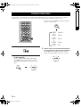
This section describes the functions of the remote control
used to control FM, XM Satellite Radio, or iPod when the
TV/AV mode is selected with the operation mode selector
(7).
1 PRESET/TUNE
FM: Switches between the preset search mode and the
frequency search mode (see pages 51 to 54).
2 Numeric buttons
FM, XM: Enter numbers.
3 Cursor buttons / / / , ENTER
FM: Use ENTRY ( / ) to change the preset station
number (1 to 8) or frequency level (see pages 51 to 54).
Use CAT/A-E ( / ) to change the preset station group
(A to E) (see pages 53 and 54). Use ENTER to confirm the
input above.
XM: Use ENTRY ( / ) to select XM channels in
All Channel Search mode/Category Search mode, and to
select the preset channel number (1 to 8) in Preset Search
mode. Use CAT/A-E ( / ) to select XM categories in
All Channel Search mode/Category Search mode, and to
select the preset channel group (A to E) in Preset Search
mode. Use ENTER to confirm the input above (see pages
7 and 8 in the Reference Guide).
y
These functions are also available when this unit is playing back
your iPod (see page 3 in the Reference Guide).
4 DISPLAY
XM and iPod: Displays information when this unit is
receiving an XM channel (see page 10 in the Reference
Guide) or playing back your iPod (see page 3 in the
Reference Guide).
5 MEMORY
FM: Stores the preset stations (see pages 52 and 53).
XM: Use to store the preset stations (see page 9 in the
Reference Guide).
6 SEARCH
FM: Switches between automatic and manual tuning (see
page 51).
XM: Switches between search modes (All Channel
Search, Category Search, and Preset Search) (see pages 7
and 8 in the Reference Guide).
7 Operation mode selector
Selects the operation mode of this unit. Select YSP when
operating this unit and select TV/AV when operating your
TV or other AV components.
4
6
321
+10
0
78
9
5
STEREO
MY BEAM
PRESET/TUNE
MEMORYSEARCH
SLEEP
INPUTMODE
ENHANCER MENU
RETURNDISPLAY
TV VOL
VOLUME
MUTE
CH LEVEL TEST
TV INPUT TV MUTE
ENTER
OFF
CODE SET
SPORTS
5BEAM ST+3BEAM 3BEAM
MUSIC MOVIE
VOL MODE
AUTO
SETUP
CATFM/XM
MACRO
TV
INPUT1
CH
ENTRY
CAT/
A-E
AUX1 AUX2
STB
TV
DVD
AUX3
TV
POWERPOWERSTANDBY/ON
DOCK
AV
YSP
TV/AV
SUR. DECODE
MY SUR.
1
2
3
4
5
6
7
01EN_YSP-4000_UA.book Page 16 Wednesday, December 26, 2007 3:00 PM
Black process 45.0° 240.0 LPI
Strona jest ładowana ...
Strona jest ładowana ...
Strona jest ładowana ...
Strona jest ładowana ...
Strona jest ładowana ...
Strona jest ładowana ...
Strona jest ładowana ...
Strona jest ładowana ...
Strona jest ładowana ...
Strona jest ładowana ...
Strona jest ładowana ...
Strona jest ładowana ...
Strona jest ładowana ...
Strona jest ładowana ...
Strona jest ładowana ...
Strona jest ładowana ...
Strona jest ładowana ...
Strona jest ładowana ...
Strona jest ładowana ...
Strona jest ładowana ...
Strona jest ładowana ...
Strona jest ładowana ...
Strona jest ładowana ...
Strona jest ładowana ...
Strona jest ładowana ...
Strona jest ładowana ...
Strona jest ładowana ...
Strona jest ładowana ...
Strona jest ładowana ...
Strona jest ładowana ...
Strona jest ładowana ...
Strona jest ładowana ...
Strona jest ładowana ...
Strona jest ładowana ...
Strona jest ładowana ...
Strona jest ładowana ...
Strona jest ładowana ...
Strona jest ładowana ...
Strona jest ładowana ...
Strona jest ładowana ...
Strona jest ładowana ...
Strona jest ładowana ...
Strona jest ładowana ...
Strona jest ładowana ...
Strona jest ładowana ...
Strona jest ładowana ...
Strona jest ładowana ...
Strona jest ładowana ...
Strona jest ładowana ...
Strona jest ładowana ...
Strona jest ładowana ...
Strona jest ładowana ...
Strona jest ładowana ...
Strona jest ładowana ...
Strona jest ładowana ...
Strona jest ładowana ...
Strona jest ładowana ...
Strona jest ładowana ...
Strona jest ładowana ...
Strona jest ładowana ...
Strona jest ładowana ...
Strona jest ładowana ...
Strona jest ładowana ...
Strona jest ładowana ...
Strona jest ładowana ...
Strona jest ładowana ...
Strona jest ładowana ...
Strona jest ładowana ...
Strona jest ładowana ...
Strona jest ładowana ...
Strona jest ładowana ...
Strona jest ładowana ...
Strona jest ładowana ...
Strona jest ładowana ...
Strona jest ładowana ...
Strona jest ładowana ...
Strona jest ładowana ...
Strona jest ładowana ...
Strona jest ładowana ...
Strona jest ładowana ...
Strona jest ładowana ...
Strona jest ładowana ...
Strona jest ładowana ...
Strona jest ładowana ...
Strona jest ładowana ...
Strona jest ładowana ...
Strona jest ładowana ...
Strona jest ładowana ...
Strona jest ładowana ...
Strona jest ładowana ...
Strona jest ładowana ...
Strona jest ładowana ...
Strona jest ładowana ...
Strona jest ładowana ...
Strona jest ładowana ...
Strona jest ładowana ...
Strona jest ładowana ...
Strona jest ładowana ...
Strona jest ładowana ...
Strona jest ładowana ...
Strona jest ładowana ...
Strona jest ładowana ...
Strona jest ładowana ...
Strona jest ładowana ...
Strona jest ładowana ...
Strona jest ładowana ...
Strona jest ładowana ...
Strona jest ładowana ...
Strona jest ładowana ...
Strona jest ładowana ...
Strona jest ładowana ...
Strona jest ładowana ...
Strona jest ładowana ...
Strona jest ładowana ...
Strona jest ładowana ...
Strona jest ładowana ...
Strona jest ładowana ...
-
 1
1
-
 2
2
-
 3
3
-
 4
4
-
 5
5
-
 6
6
-
 7
7
-
 8
8
-
 9
9
-
 10
10
-
 11
11
-
 12
12
-
 13
13
-
 14
14
-
 15
15
-
 16
16
-
 17
17
-
 18
18
-
 19
19
-
 20
20
-
 21
21
-
 22
22
-
 23
23
-
 24
24
-
 25
25
-
 26
26
-
 27
27
-
 28
28
-
 29
29
-
 30
30
-
 31
31
-
 32
32
-
 33
33
-
 34
34
-
 35
35
-
 36
36
-
 37
37
-
 38
38
-
 39
39
-
 40
40
-
 41
41
-
 42
42
-
 43
43
-
 44
44
-
 45
45
-
 46
46
-
 47
47
-
 48
48
-
 49
49
-
 50
50
-
 51
51
-
 52
52
-
 53
53
-
 54
54
-
 55
55
-
 56
56
-
 57
57
-
 58
58
-
 59
59
-
 60
60
-
 61
61
-
 62
62
-
 63
63
-
 64
64
-
 65
65
-
 66
66
-
 67
67
-
 68
68
-
 69
69
-
 70
70
-
 71
71
-
 72
72
-
 73
73
-
 74
74
-
 75
75
-
 76
76
-
 77
77
-
 78
78
-
 79
79
-
 80
80
-
 81
81
-
 82
82
-
 83
83
-
 84
84
-
 85
85
-
 86
86
-
 87
87
-
 88
88
-
 89
89
-
 90
90
-
 91
91
-
 92
92
-
 93
93
-
 94
94
-
 95
95
-
 96
96
-
 97
97
-
 98
98
-
 99
99
-
 100
100
-
 101
101
-
 102
102
-
 103
103
-
 104
104
-
 105
105
-
 106
106
-
 107
107
-
 108
108
-
 109
109
-
 110
110
-
 111
111
-
 112
112
-
 113
113
-
 114
114
-
 115
115
-
 116
116
-
 117
117
-
 118
118
-
 119
119
-
 120
120
-
 121
121
-
 122
122
-
 123
123
-
 124
124
-
 125
125
-
 126
126
-
 127
127
-
 128
128
-
 129
129
-
 130
130
-
 131
131
-
 132
132
-
 133
133
-
 134
134
-
 135
135
-
 136
136
-
 137
137


Yamaha YSP-4000 Instrukcja obsługi
- Kategoria
- Dodatkowy sprzęt muzyczny
- Typ
- Instrukcja obsługi
w innych językach
- čeština: Yamaha YSP-4000 Návod k obsluze
- español: Yamaha YSP-4000 El manual del propietario
- italiano: Yamaha YSP-4000 Manuale del proprietario
- Deutsch: Yamaha YSP-4000 Bedienungsanleitung
- svenska: Yamaha YSP-4000 Bruksanvisning
- português: Yamaha YSP-4000 Manual do proprietário
- français: Yamaha YSP-4000 Le manuel du propriétaire
- Türkçe: Yamaha YSP-4000 El kitabı
- English: Yamaha YSP-4000 Owner's manual
- dansk: Yamaha YSP-4000 Brugervejledning
- русский: Yamaha YSP-4000 Инструкция по применению
- suomi: Yamaha YSP-4000 Omistajan opas
- Nederlands: Yamaha YSP-4000 de handleiding
- română: Yamaha YSP-4000 Manualul proprietarului
Powiązane dokumenty
-
Yamaha YSP-1 Instrukcja obsługi
-
-
Yamaha YSP800S - Digital Sound Projector Five CH Speaker Instrukcja obsługi
-
Yamaha YSP-3000 Instrukcja obsługi
-
-
-
Yamaha YSP-4100 Instrukcja obsługi
-
-
-
Yamaha RXV363-B - Home Theater Receiver Instrukcja obsługi
Inne dokumenty
-
Sony ZSY2L Karta katalogowa
-
-
Sony KD-65AF9 Instrukcja obsługi
-
Acer AT3720A Skrócona instrukcja obsługi
-
Bose Personal Music Center III Instrukcja obsługi
-
 Pyle Pro PLRSTN14UX2 Instrukcja obsługi
-
Philips SJM3152 Instrukcja obsługi
-
Philips SJM3151 Instrukcja obsługi
-
Thomson ROC 740 Instrukcja obsługi
-
Sansui SLEDVD197 Karta katalogowa
