
World class hi-fi made in England.


Introduction
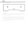
The function of a phono pre amplier is to match the output from a pick
up cartridge to the input of a line level amplier. It is required to amplify
the very low signals produced by the cartridge and also to equalise the
frequency curve in accordance with RIAA record cutting standard.
Moving coil (MC) and moving magnet (MM) cartridges require different
types of phono pre ampliers to achieve optimum performance. The Aria
uses two separate circuits dedicated to both moving coil and moving
magnet cartridges and avoids compromises.
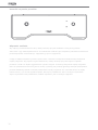
The Aria is an “all analogue amplier” with no digital control circuitry.
The fully aluminium case screens the internal circuit from any stray RFI
signals.
We have avoided including any superuous gadgets as they obstruct
the signal path and degrade the sound quality. The Aria incorporates
remarkable and innovative design ideas. These innovations are described
more fully in the technology section of this manual.
Alternatively, you can simply switch on, sit back and let your Aria sing for
itself.
Introduction
Technology
Installation
Back Panel Connectivity
Loading Seings
Front Panel Indicators
MC Cartridge Adjustment
Technical Specications
Important Notes
English
Français
Deutsch
Italiano
Español
Português
Nederlands
Dansk
Svenska
Polski
1
9
17
25
33
41
49
57
65
73
1
2
2
3
3
4
5
6
7
1

Technology
The Aria has two entirely separate high performance phono stages. One fully adjustable dedicated
moving coil and a moving magnet stage. Each stage has its own separate input sockets and input
pre amplier circuitry. This enables Rega to design bespoke input circuitry for each cartridge without
compromise. The MM/MC signal switching is performed at a high level and a low impedance using
relays thus not causing any degradation of the signal.
The MC input uses parallel connected low noise FET’s (Field Effect Transistor) congured as a
compound pair conguration. The use of FET transistors ensures there is no bias current owing in the
cartridge coil so as not to upset the delicate magnetic geometry of the cartridge. The MC input has the
provision for selecting resistive input loading of 70 to 400Ω and capacitive loading of 1000 to 4200pF.
The input sensitivity can be changed by 6dB, via the back panel.
The MM input uses low noise bipolar input transistors also congured as a compound pair. There
are two separate power supplies for each channel and further sub power supplies for each of the
low noise input circuits. Nichicon FG electrolytic capacitors have been used in critical positions in
the power supplies. ICEL and Wima polypropylene capacitors have been used in the signal path and
equalisation networks. Discrete circuitry is used throughout the signal path ensuring full control of the
circuit design.
Installation
The Aria will work well on most surfaces, provided there is sufcient air around it to prevent
overheating. To avoid any possible magnetic interference and increased hum levels, position the Aria
as far away from the turntable as the tonearm lead will allow, this ensures all delicate electronics are
kept away from other transformers and motors etc. Try not to stack other Hi-Fi components directly
on top of each other. Given the nature of sensitive high gain phono ampliers, the Aria may need
placing away from high power ampliers that use large transformers. If in the rare event that low level
noise should become overly intrusive, try using the lower gain setting, and move the unit away from
possible noise sources as described.
The minimal heat produced by the Aria is dissipated by the case, particularly the left hand side. Try to
ensure that the case has an uninterrupted air passage around it. The Aria circuit has been carefully
designed to work with a minimal “warm up” period of just a few minutes as the sensitive input circuits
stabilise and reach their optimal operating conditions. The MC input circuit uses a self-adjusting servo
control to keep the MC input circuit at its optimum operating point, compensating for any variations in
ambient and operating temperature.
2

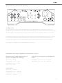
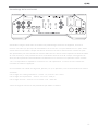
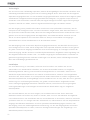
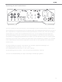
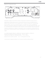
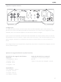
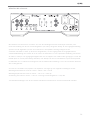
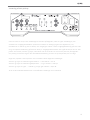
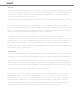
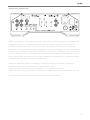
Setup
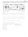
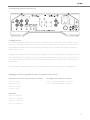
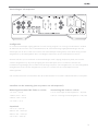
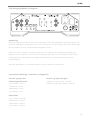
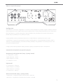
Separate inputs are used for moving magnet and moving coil cartridges. Connect your turntable’s
tonearm cable to the appropriate input sockets on the back of the Aria. If your tonearm has a separate
earth this should be rmly connected to the earth terminal shown on the rear panel in the diagram
above.
Connect the Aria to your amplier via the sockets marked Output to the appropriate line level input on
the back of your amplier. Use a high quality phono cable such as the Rega Couple 2 (not supplied).
The mains power lead (supplied) should be connected to the IEC socket on the right hand side located
above the fuse holder.
N.B. Always switch both pre and power amps off before changing any connections.
Le and Right MC Loading Resistance
1 and 2 off = 400 Ω
1 only on = 100 Ω
2 only on = 150 Ω
1 and 2 on = 70 Ω
Capacitance
3 and 4 off = 1000 pF
3 only on = 2000 pF
4 only on = 3200 pF
3 and 4 on = 4200 pF
Le and Right MC Gain
1 off and 2 on low gain = 63.5 dB
1 on and 2 off high gain = 69.3 dB
Back Panel Connectivity
Loading Seings (Adjustable via back panel)
3

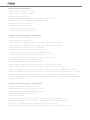
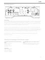
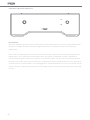
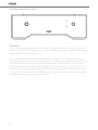
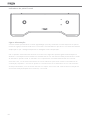
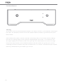
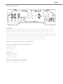
Powering Up
The Aria is activated by pressing the On/Off button situated to the left of the control panel. The REGA
logo will glow RED. It is recommended to activate the Aria before the power ampliers and deactivate
after they have been switched off.
N.B. The unit will be muted for approximately 5 seconds when powered-up or switching between
inputs. MM or MC inputs are selected by pressing the input button on the front panel. The LED
indicator will show the selected input. When switching between MM & MC the Aria goes into mute
briey to avoid any intrusive switching noise whilst the circuitry settles. When switching between MC
and MM both LED’s will temporarily light, with a short delay in the audible ‘click’ of the relay. This is a
function of the mute and relay contact cleaning / activation circuit and is normal.
Front Panel Indicators
4

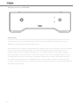
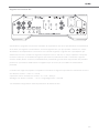
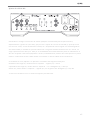
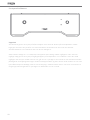
IMPORTANT: Turn off the Aria before changing any of the settings on the back, especially the MC Gain
setting which causes the MC input circuit to re-adjust. This may cause a big ‘thump’ through the
speakers if the amplier is on and the Aria is the source component. The MC input has the provision
for selecting resistive input loading of 70 to 400 Ω and capacitive loading of 1000 to 4200 pF. The input
sensitivity can also be changed by 6 dB. You must adjust each channel (left and right) individually,
via the use of the dip switches located on the back panel. Your cartridge manufacturer will state the
recommended loading for the model MC cartridge you have chosen.
The Rega Ania, Apheta 2 or Aphelion MC models require the following settings:
Left and Right MC Loading Resistance - 1 only on = 100 Ω
Left and Right MC Loading Capacitance - 3 and 4 off = 1000 pF
Left and Right MC Gain - 1 on and 2 off high gain = 69.3 dB
*The Aria will be factory set to the above settings by default.
MC Cartridge Adjustment
5

Technical Specications
Maximum output level = 11 V RMS
Rated output level = 200 mV
Output resistance = 100 Ω
Minimum output resistance for a –3 dB point at 15 Hz = 1 k
AC supply 230 V & 115 V Nominal +/- 10%.
230 V / 20 mm Fuse / T250 mA L
115 V / 20 mm Fuse / T500 mA L
Power Consumption = 10 Watts
Ambient operating temperature 5 to 35 °C
Technical Specications / MC Input
Generator source resistance = 15 Ω
Loading set to 100 Ω and 4200 pF
Input sensitivity (0 dB high gain setting) = 70 µV for 200 mV output
Input sensitivity (-6 dB low gain setting) = 133 µV for 200 mV output
Resistive input loading = 70, 100, 150 & 400 Ω
Resistive input loading = 70, 100, 150 & 400 Ω
Capacitive input loading = 1000, 2000, 3200 & 4200 pF
Maximum input level (0 dB high gain setting) = 5.1 mV at 1 kHz
Maximum input level (-6 dB high gain setting) = 10 mV at 1 kHz
Gain (0 dB high gain setting) = 69.3 dB at 1 kHz
Gain (-6 dB low gain setting) = 63.5 dB at 1 kHz
Frequency response (100 kΩ output load) = 13 Hz (-3 dB) to 70 kHz (-0.2 dB)
RIAA accuracy (100 kΩ output load) = better than +/-0.2 dB 70 Hz to 70kHz
THD+Noise (-6 dB low gain setting) = typically 0.035% at 1 V Bandwidth 100 Hz to 22 kHz
Noise (15 Ω terminator and -6 dB low gain setting) = typically –71 dB V un-weighted 100 Hz to 22 kHz
Signal to noise ratio (un-weighted 100 Hz - 22kHz bandwidth and 0 dB high gain setting) = -67 dB using
1 kHz 5 cm/sec track on the HFS69 test record and Apheta cartridge tted to a RP8 turntable.
Technical Specications / MM Input
Generator source resistance = 40 Ω
Input sensitivity = 1.7 mV for 200 mV output
Input loading = 47 k in parallel with 100 pF
Maximum input level = 93 mV at 1 kHz
Gain = 41.4 dB at 1 kHz
Frequency response (100 kΩ output load) = 15 Hz (-3 dB) to 100 kHz (-0.2 dB)
RIAA accuracy (100 kΩ output load) = better than +/-0.2 dB 100 Hz to 100 kHz
THD+Noise = typically 0.005% at 1 V Bandwidth 100 Hz to 22 kHz
Noise (150 Ω terminator on input) = typically –86 dB V un-weighted 100 Hz to 22 kHz
6

Important Notes
Allow adequate air circulation around the left hand side of the unit as this houses the heat sink for
the power supply. It will typically run 5° C above the ambient temperature. Recommended distance
between this side and other units is 60 mm. This unit is intended for use in moderate climates.
To reduce the risk of re, electric shock or product damage, do not expose the unit to rain, moisture,
dripping or splashing and ensure that no objects lled with liquids, such as vases shall be placed upon
it. Do not remove the case covers, there are no user serviceable parts inside.
7

8

Introduction
La fonction d’un préamplicateur phono est d’augmenter le niveau de
sortie d’une cellule phonolectrice au point où il est compatible avec l’entrée
ligne d’un préamplicateur. Il doit amplier le signal inniment petit d’une
cellule et égaliser la courbe de fréquences en accord avec les normes RIAA.
An d’assurer les meilleures performances, les cellules MM (à aimant
mobile) et MC (à bobine mobile) ont besoin de types de traitement
différents. L’Aria possède deux circuits séparés (MM et MC) et évite ainsi les
compromis.
L’Aria est un préamplicateur “tout analogique” sans aucun élément
numérique. Le châssis entièrement en aluminium protège les circuits
internes contre les “parasites” RFI.
Nous avons omis les “gadgets” superus qui nuisent au chemin du signal
et dégradent la qualité sonore. L’Aria utilise plusieurs idées remarquables et
innovantes. Ces innovations sont décrites dans la partie “Technologie” du
présent fascicule.
Ou bien, vous pouvez vous contenter de brancher l’Aria et le laisser chanter.
Introduction
Technologie
Installation
Branchements à l’arrière du panneau
Paramètres de charge
Voyants sur le panneau avant
Paramétrage de la section MC
Spécications techniques
Remarques importantes
English
Français
Deutsch
Italiano
Español
Português
Nederlands
Dansk
Svenska
Polski
9
10
10
11
11
12
13
14
15
1
9
17
25
33
41
49
57
65
73
9

Technologie
L’Aria se compose de deux étages phono complètement séparés. L’un, destiné aux MC est entièrement
paramétrable : l’autre est xe. Chaque étage a ses propre prises d’entrée et son propre circuit. La
commutation du signal MM/MC est traitée à haut niveau et à basse impédance utilisant des relais an
de ne pas dégrader le signal.
L’entrée MC utilise des FET (transistors à effet de champ) connectés en parallèle congurés en paires
compound. Les transistors FET éliminent le passage de courant vers la bobine de la cellule, préservant
ainsi l’équilibre magnétique délicat de celle-ci. L’entrée MC peut être paramétrée pour une impédance
d’entrée de 70 à 400 Ω et pour une capacitance de 1000 à 4.200 pF. La sensibilité d’entrée peut être
altérée de 6 dB à l’aide des micro switchs sur le panneau arrière.
L’entrée MM utilise des transistors bipolaires également congurés en paires compound. Il y a deux
alimentations pour chaque canal et des sous-alimentations pour chacun des circuits d’entrée à
faible bruit. Des capacitances électrolytiques Nichicon FC sont utilisés aux positions critiques dans
les alimentations. Sur le chemin du signal et de l’égalisation, on a fait appel à des capacitances en
polypropylène ICEL et WIMA. Des circuits discrets sont utilisés sur le chemin du signal, assurant une
parfaite maîtrise de l’architecture du circuit.
Installation
L’Aria fonctionnera bien posé normalement sur la plupart des surfaces, pourvu que l’air puisse circuler
librement autour de l’appareil. Pour éviter toute interférence magnétique entraînent des ronements
accrus, l’Aria doit être installé aussi éloigné de la platine tourne-disque que le cordon de liaison le
permet. De cette façon, les électroniques sensibles sont éloignés de transformateurs, moteurs, etc.
Dans la mesure du possible, essayer de ne pas entasser directement les éléments de votre chaîne.
Etant donné la nature sensible des amplis phono à haut gain, il est préférable de placer l’Aria le plus
loin possible d’amplis puissants avec de gros transformateurs. Au cas peu probable où un bruit de font
devient envahissant, essayez l’option de gain le plus.
La faible chaleur générée par l’appareil, bien que minime, est dispersée par le châssis — notamment
par le côté gauche. Assurez-vous qu’il y a une libre circulation d’air autour de l’appareil. Le circuit de
l’Aria a été conçu pour fonctionner “normalement” après une période de chauffe de seulement quelques
minutes. Pendant ce temps, les circuits d’entrée se stabilisent et atteignent leur température optimale.
Le circuit MC utilise un servo- contrôle automatique qui maintient cette température malgré les
variations intérieures et extérieures.
10

Conguration
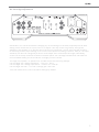
Il y a deux paires de prises d’entrée séparées pour les cellules MM et MC. Branchez le cordon de
modulation de votre platine sur les prises d’entrée appropriées. Si votre bras de lecture possède un l
de masse séparé, connectez-le fermement à la borne de terre sur le panneau arrière (voir schéma).
Connectez les prises de sortie (Output) de votre Aria à l’une des entrées ligne de votre ampli. Préférez
un cordon de modulation de bonne qualité tel un Rega Couple 2 (non fourni). Branchez le cordon
(compris) sur la prise IEC sur le côté droit de la face arrière et juste au-dessus du porte-fusible.
NB. Eteignez vos appareils avant de modier les connexions.
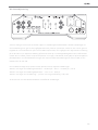
Résistances de charge MC gauche et
droite (Le/Right MC Loading)
1 et 2 « off » = 400 Ω
Uniquement 1 « on » = 100 Ω
Uniquement 2 « on » = 150 Ω
1 et 2 « on » = 70 Ω
Capacitance
3 et 4 « off » = 1000 pF
Uniquement 3 « on » = 2000 pF
Uniquement 4 « on » = 3200 pF
3 et 4 « on » = 4200 pF
Gain MC droit et gauche (Le/Right MC
Gain)
Gain faible 1 « off » et 2 « on » = 63,5 dB
Gain élevé 1 « on » et 2 « off » = 69,3 dB
Branchements à l’arrière du panneau
Paramètres de charge (réglables via le panneau arrière)
11

Mise en route
La mise en route de l’Aria s’effectue en appuyant sur le bouton situé à gauche de la façade. La diode
rouge incorporée dans le logo REGA s’allume. Il est recommandé d’allumer l’Aria avant vos amplis de
puissance et de l’éteindre après ceux-ci.
NB. L’appareil se met en MUTE pendant 5 secondes environ lors de la mise en route ou lors du
passage d’une entrée à l’autre. Les entrées MM et MC sont sélectionnées en appuyant sur le bouton
“Input” sur la face avant: une diode indique l’entrée sélectionnée. Lors d’une commutation entre les
entrées, l’Aria se met en mute an d’éviter les bruits parasites pendant la stabilisation des circuits.
Pendant ce temps, les 2 diodes restent simultanément allumées. Enn le relais s’enclenche avec un «
clic » - ceci est parfaitement normal.
Voyants sur le panneau avant
12

IMPORTANT: Eteignez l’Aria avant de modier les paramétrages à l’arrière de l’appareil, surtout la
fonction “MC Gain” qui provoque la réinitialisation du circuit MC. Ceci peut déclencher un “ploc” assez
violent dans les enceintes si l’ampli est allumé et l’Aria est la source sélectionnée. L’entrée MC peut
être paramétrée pour des résistances d’entrée allant de 70 à 400 Ω et des capacitances d’entrée allant
de 1.000 à 4.200 pF. Il est possible de varier la sensibilité d’entrée de 6 dB. Chaque canal (gauche et
droit) doit être paramétré individuellement à l’aide des micro switchs sur le panneau arrière. Switchs
1 et 2 correspondent à l’impédance: Switchs 3 et 4 à la capacitance. La notice de votre cellule MC
montrera les valeurs à appliquer.
Si vous utilisez une cellule MC Rega Ania, Apheta (1 ou 2) ou Aphelion, nous recommandons les valeurs
suivantes:
Left et Right MC Loading Resistance - Switch 1 on, Switch 2 off = 100 Ω
Left et Right MC Capacitance - Switch 3 et 4 off = 1000 pF
Left et Right MC Gain - Switch 1 on et Switch 2 off = 69.3 dB
*L’Aria est réglé en usine avec les paramètres par défaut ci-dessus.
Paramétrage de la section MC
13

Spécications techniques
Niveau de sortie maximale = 11 V RMS
Niveau de sortie nominal = 200 mV
Résistance de sortie = 100 Ω
Résistance de sortie minimale pour un point de –3 dB à 15 Hz = 1 k
Alimentation c.a. 230 V et courant nominal 115 V +/- 10%
Fusible 230 V / 20 mm / T250 mA L
Fusible 115 V / 20 mm / T500 mA L
Consommation électrique = 10 Watts
Température de fonctionnement 5 à 35° C
Spécications techniques / Entrée MC
Résistance de source du générateur = 15 Ω
Valeurs réglées à 100 Ω et 4200 pF
Sensibilité d’entrée (réglage gain élevé 0 dB) = 70 µV pour 200 mV en sortie
Sensibilité d’entrée (réglage gain faible -6 dB) = 133 µV pour 200 mV en sortie
Charges résistives en entrée = 70, 100, 150 et 400 Ω
Charges résistives en entrée = 70, 100, 150 et 400 Ω
Charges capacitives en entrée = 1000, 2000, 3200 et 4200 pF
Niveau d’entrée maximal (réglage gain élevé 0 dB) = 5,1 mV à 1 kHz
Niveau d’entrée maximal (réglage gain élevé -6 dB) = 10 mV à 1 kHz
Gain (réglage gain élevé 0 dB) = 69,3 dB à 1 kHz
Gain (réglage gain faible -6 dB) = 63,5 dB à 1 kHz
Bande passante (charge en sortie 100 kΩ) = 13 Hz (-3 dB) à 70 kHz (-0,2 dB)
Précision RIAA (charge en sortie 100 kΩ) = meilleure que +/-0,2 dB 70 Hz à 70 kHz
Bruit THD+ (réglage gain faible -6 dB) = en général, 0,035% à 1 V Bande passante 100 Hz à 22 kHz
Bruit (terminateur 15 Ω et réglage gain faible -6 dB) = en général –71 dB V non pondéré 100 Hz à 22 kHz
Rapport signal/bruit (bande passante 100 Hz - 22 kHz non pondérée et réglage gain élevé 0 dB) =
-67 dB en utilisant une piste 1 kHz 5 cm/s sur un disque test HFS69 et une cellule Apheta installée sur
un tourne-disque RP8.
Spécications techniques / Entrée MM
Résistance de source du générateur = 40 Ω
Sensibilité d’entrée = 1,7 mV pour 200 mV en sortie
Charge en entrée = 47 k en parallèle avec 100 pF
Niveau d’entrée maximal = 93 mV à 1 kHz
Gain = 41,4 dB à 1 kHz
Bande passante (charge en sortie 100 kΩ) = 15 Hz (-3 dB) à 100 kHz (-0,2 dB)
Précision RIAA (charge en sortie 100 kΩ) = meilleure que +/-0,2 dB 100 Hz à 100 kHz
Bruit THD+ = en général 0,005% à 1 V Bande passante 100 Hz à 22 kHz
Bruit (terminateur 150 Ω sur entrée) = en général –86 dB V non pondéré 100 Hz à 22 kHz
14

Remarques importantes
Températures ambiantes d’opération: entre 5° C et 35° C. Prévoyez une bonne circulation d’air autour
de l’appareil, surtout côté gauche car c’est ici que se trouvent les radiateurs de l’alimentation. En
général, cette partie sera plus chaud de 5° C que la température ambiante. Laissez au moins 60 mm
entre l’Aria et tout autre appareil. Cette machine est destinée aux climats tempérés.
Avertissement: an de réduire le risque d’incendie, de choc électrique ou de dégradation de l’appareil,
n’exposez pas ce produit à l’eau sous toutes ses formes. Ne placez aucun conteneur rempli d’eau
(vase etc) sur l’appareil. N’ouvrez pas ce produit. Il ne contient aucune pièce susceptible d’être
transformée par l’utilisateur.
15

16

Einleitung
Der Phono-Vorverstärker dient dazu, den Ausgangspegel eines Tonab-
nehmers mit den Line- Eingang eines Verstärkers abzustimmen. Er ist
erforderlich, um die sehr geringen Signale, die vom Tonabnehmer produziert
werden, zu verstärken, aber auch ,um den Frequenzgang gemäß der RIAA-
Norm anzupassen.
Moving Coil (MC) und Moving Magnet (MM) erfordern unterschiedliche
Arten von Vorverstärkern, um eine optimale Klangqualität zu erzielen. Beim
Aria kommen zwei separate Schaltungen zum Einsatz, die für MM- bzw.
MC-Tonabnehmer vorgesehen sind. Dadurch sind keine Kompromisse
erforderlich.
Der Aria ist ein vollständig analoger Verstärker ohne digitalen Regelkreis.
Das Gehäuse, das vollständig aus Aluminium besteht, schirmt den inneren
Schaltkreis von RFI-Streusignalen ab.
Wir haben es vermieden, überüssige Ausstattungsmerkmale zu integrieren,
da diese den Signalweg beeinussen und die Tonqualität verschlechtern.
Der Aria umfasst bemerkenswerte, innovative Design-Ideen. Diese
Innovationen sind im Technologie-Abschnitt dieses Handbuchs umfassender
beschrieben.
Sie können ihn aber auch einfach einschalten, sich zurücklehnen und Ihren
Aria selbst „singen“ lassen.
Einleitung
Technologie
Installation
Rückseitige Anschlüsse
Laden der Einstellungen
Anzeigen an der Frontblende
Anpassung des MC-Tonabnehmers
Technische Daten
Wichtige Anmerkungen
English
Français
Deutsch
Italiano
Español
Português
Nederlands
Dansk
Svenska
Polski
17
18
18
19
19
20
21
22
23
1
9
17
25
33
41
49
57
65
73
17

Technologie
Der Aria ist mit zwei vollständig separaten, äußerst leistungsfähigen Phonostufen versehen. Eine
vollständig einstellbare Moving Coil und eine Moving Magnet Stufe. Jede Stufe hat ihre eigenen
separaten Eingangsbuchsen und Vorverstärker-Eingangsschaltkreise. Dadurch kann Rega für jeden
Tonabnehmer maßgeschneiderte Eingangsschaltkreise designen, um jegliche Kompromisse zu
vermeiden. Das Umschalten zwischen MM-/MC-Signal erfolgt bei hohem Pegel und bei geringer
Impedanz mithilfe von Relais, wodurch Signalverschlechterungen vermieden werden.
Der MC-Eingang nutzt parallel verbundene rauscharme FETs (Field Effect Transistor), die als
Compound-Paar konguriert sind. Die FET-Transistoren sorgen dafür, dass kein Bias-Strom in
der Spule des Tonabnehmers ießt, damit die feine Magnet-Geometrie des Tonabnehmers nicht
gestört wird. Der MC-Eingang bietet die Möglichkeit, eine Widerstandslast zwischen 70 und
400 Ω und eine kapazitive Last zwischen 1000 und 4200 pF auszuwählen Die Eingangs-
Sensibilität kann auf der Rückblende um 6 dB verändert werden.
Der MM-Eingang nutzt rauscharme bipolare Eingangstransistoren, die ebenfalls als Compund-
Paar konguriert sind. Jeder Kanal verfügt über zwei separate Netzteile, darüber hinaus gibt es
für jeden rauscharmen Eingangs-Schaltkreis eine Stromversorgung. An wichtigen Punkten der
Stromversorgung werden Nichicon FG-Elektrolytkondensatoren eingesetzt. Beim Signalweg und
den Abgleichnetzwerken werden ICEL- und WIMA-Polypropylen-Kondensatoren verwendet. Im
gesamten Signalweg kommen diskrete Schaltungen zum Einsatz, damit vollständige Kontrolle
über das Schaltdesign gewährleistet ist.
Installation
Um eine Überhitzung zu vermeiden, sollte der Aria frei stehen. Sie sollten den Aria so
weit entfernt von Plattensieler aufstellen, wie es das Tonarmkabel zulässt, um mögliche
elektromagnetische Störung und vermehrte Brummgeräusche zu vermeiden. Dadurch wird
sämtliche empndliche Elektronik von anderen Transformatoren, Motoren usw. ferngehalten.
Versuchen Sie, keine anderen Hi-Fi-Komponenten direkt aufeinander zu stellen. Angesichts der
Bauweise empndlicher, leistungsfähiger Phono-Verstärker kann es sein, dass der Aria in gewisser
Entfernung von Hochleistungsverstärkern mit großen Transformatoren aufgestellt werden
muss. Sollte geringpegeliges Rauschen Überhand nehmen, versuchen Sie es mit geringeren
Leistungseinstellungen und bewegen Sie das Gerät wie beschrieben weg von möglichen
Rauschquellen.
Die minimale Wärme, die vom Aria ausgeht, wird insbesondere auf der linken Seite des
Gehäuses verteilt. Versuchen Sie, darauf zu achten, dass rund um das Gehäuse durchgehend
Luft zirkulieren kann. Der Schaltkreis des Aria wurde bewusst so entworfen, dass eine minimale
„Aufwärm“-Zeit von nur wenigen Minuten erforderlich ist, während derer sich die empndlichen
Eingangs-Schaltkreise stabilisieren und ihre optimalen Betriebsbedingungen erreichen. Der
MC-Eingang nutzt eine selbstregelnde Servosteuerung, um den MC-Eingangskreis auf seinem
optimalen Betriebspunkt zu halten, indem sie etwaige Schwankungen der Umgebungs- und
Betriebstemperatur kompensiert.
18
Strona się ładuje...
Strona się ładuje...
Strona się ładuje...
Strona się ładuje...
Strona się ładuje...
Strona się ładuje...
Strona się ładuje...
Strona się ładuje...
Strona się ładuje...
Strona się ładuje...
Strona się ładuje...
Strona się ładuje...
Strona się ładuje...
Strona się ładuje...
Strona się ładuje...
Strona się ładuje...
Strona się ładuje...
Strona się ładuje...
Strona się ładuje...
Strona się ładuje...
Strona się ładuje...
Strona się ładuje...
Strona się ładuje...
Strona się ładuje...
Strona się ładuje...
Strona się ładuje...
Strona się ładuje...
Strona się ładuje...
Strona się ładuje...
Strona się ładuje...
Strona się ładuje...
Strona się ładuje...
Strona się ładuje...
Strona się ładuje...
Strona się ładuje...
Strona się ładuje...
Strona się ładuje...
Strona się ładuje...
Strona się ładuje...
Strona się ładuje...
Strona się ładuje...
Strona się ładuje...
Strona się ładuje...
Strona się ładuje...
Strona się ładuje...
Strona się ładuje...
Strona się ładuje...
Strona się ładuje...
Strona się ładuje...
Strona się ładuje...
Strona się ładuje...
Strona się ładuje...
Strona się ładuje...
Strona się ładuje...
Strona się ładuje...
Strona się ładuje...
Strona się ładuje...
Strona się ładuje...
Strona się ładuje...
Strona się ładuje...
Strona się ładuje...
Strona się ładuje...
Strona się ładuje...
Strona się ładuje...
-
 1
1
-
 2
2
-
 3
3
-
 4
4
-
 5
5
-
 6
6
-
 7
7
-
 8
8
-
 9
9
-
 10
10
-
 11
11
-
 12
12
-
 13
13
-
 14
14
-
 15
15
-
 16
16
-
 17
17
-
 18
18
-
 19
19
-
 20
20
-
 21
21
-
 22
22
-
 23
23
-
 24
24
-
 25
25
-
 26
26
-
 27
27
-
 28
28
-
 29
29
-
 30
30
-
 31
31
-
 32
32
-
 33
33
-
 34
34
-
 35
35
-
 36
36
-
 37
37
-
 38
38
-
 39
39
-
 40
40
-
 41
41
-
 42
42
-
 43
43
-
 44
44
-
 45
45
-
 46
46
-
 47
47
-
 48
48
-
 49
49
-
 50
50
-
 51
51
-
 52
52
-
 53
53
-
 54
54
-
 55
55
-
 56
56
-
 57
57
-
 58
58
-
 59
59
-
 60
60
-
 61
61
-
 62
62
-
 63
63
-
 64
64
-
 65
65
-
 66
66
-
 67
67
-
 68
68
-
 69
69
-
 70
70
-
 71
71
-
 72
72
-
 73
73
-
 74
74
-
 75
75
-
 76
76
-
 77
77
-
 78
78
-
 79
79
-
 80
80
-
 81
81
-
 82
82
-
 83
83
-
 84
84


w innych językach
- español: Rega Aria MM / MC Manual de usuario
- italiano: Rega Aria MM / MC Manuale utente
- Deutsch: Rega Aria MM / MC Benutzerhandbuch
- svenska: Rega Aria MM / MC Användarmanual
- português: Rega Aria MM / MC Manual do usuário
- français: Rega Aria MM / MC Manuel utilisateur
- dansk: Rega Aria MM / MC Brugermanual
- Nederlands: Rega Aria MM / MC Handleiding
Powiązane artykuły
-
Rega Aura Reference MC Instrukcja obsługi
-
-
Rega io Integrated Amplifier Instrukcja obsługi
-
Rega Fono MM Instrukcja obsługi
-
Rega Planar 1 Plus noir brillant Instrukcja obsługi
-
-
-
-
-