Makita 4326 Instrukcja obsługi

Kategoria
Wyrzynarki akumulatorowe
Typ
Instrukcja obsługi

Ten podręcznik jest również odpowiedni dla

1
GB
Jig Saw INSTRUCTION MANUAL
UA
  
PL
Wyrzynarka INSTRUKCJA OBSUGI
RO
Ferstru pendular MANUAL DE INSTRUCIUNI
DE
Stichsäge BEDIENUNGSANLEITUNG
HU
Szúrófrész HASZNÁLATI KÉZIKÖNYV
SK
Lupienková píla NÁVOD NA OBSLUHU
CZ
Elektronická pímoará pila s pedkyvem
NÁVOD K OBSLUZE
4326
4327
4328
4329
2
1
1 008153
1
2
2 008082
1
3 008167
1
2
3
4 008083
1
2
3
5 008084
1
2
6 008085
1
2
3
4
5
6
7 008154
1
8 008086
1
2
9 008087
10 008088
1
2
3
11 008089
1
2
12 008090
3
1
2
3
13 008091
1
14 008092 15 008093
16 008094
1
2
17 008095
1
2
18 008100
1
2
19 008101
1
2
20 008102
4
ENGLISH (Original instructions)
Explanation of general view
1-1. Cutting action changing lever
2-1. Switch trigger
2-2. Lock button
3-1. Speed adjusting dial
4-1. Blade holder
4-2. Bolt
4-3. Hex wrench
5-1. Bolt
5-2. Blade
5-3. Roller
6-1. Hook
6-2. Hex wrench
7-1. Blade
7-2. Roller
7-3. Retainer
7-4. Hex wrench
7-5. Bolt
7-6. Base
8-1. Dust cover
9-1. Cutting line
9-2. Base
11-1. Hex wrench
11-2. Bolt
11-3. Base
12-1. Edge
12-2. Graduation
13-1. Hex wrench
13-2. Bolt
13-3. Base
14-1. Starting hole
17-1. Dust cover
17-2. Hose
18-1. Anti-splintering device
18-2. Protrusions
19-1. Anti-splintering device
19-2. Aluminum base
20-1. Cover plate
20-2. Aluminum base
SPECIFICATIONS
Model 4326 4327 4328 4329
Length of stroke 18 mm 18 mm 18 mm 18 mm
Blade type B type
Wood 65 mm 65 mm 65 mm 65 mm
Max. cutting
capacities
Mild steel 6 mm 6 mm 6 mm 6 mm
Strokes per minute (min
-1
) 3,100 500 - 3,100 500 - 3,100 500 - 3,100
217 mm (Steel base type) 217 mm (Steel base type)
Overall length
223 mm
(Aluminum base type)
223 mm
(Aluminum base type)
217 mm 223 mm
1.8 kg (Steel base type) 1.8 kg (Steel base type)
Net weight
1.9 kg
(Aluminum base type)
1.9 kg
(Aluminum base type)
1.8 kg 1.9 kg
Safety class /II /II /II /II
• Due to our continuing program of research and development, the specifications herein are subject to change without notice.
• Specifications may differ from country to country.
• Weight according to EPTA-Procedure 01/2003
ENE019-1
Intended use
The tool is intended for the sawing of wood, plastic and
metal materials. As a result of the extensive accessory
and saw blade program, the tool can be used for many
purposes and is very well suited for curved or circular
cuts.
ENF002-2
Power supply
The tool should be connected only to a power supply of
the same voltage as indicated on the nameplate, and
can only be operated on single-phase AC supply. They
are double-insulated and can, therefore, also be used
from sockets without earth wire.
ENG905-1
Noise
The typical A-weighted noise level determined
according to EN60745:
Model 4326,4327
Sound pressure level (L
pA
) : 86 dB(A)
Sound power level (L
WA
) : 97 dB(A)
Uncertainty (K) : 3 dB(A)
Model 4328,4329
Sound pressure level (L
pA
) : 83 dB(A)
Sound power level (L
WA
) : 94 dB(A)
Uncertainty (K) : 3 dB(A)
Wear ear protection
ENG900-1
Vibration
The vibration total value (tri-axial vector sum)
determined according to EN60745:
5
Model 4326,4327
Work mode : cutting boards
Vibration emission (a
h,B
) : 5.0 m/s
2
Uncertainty (K) : 1.5 m/s
2
Work mode : cutting sheet metal
Vibration emission (a
h,M
) : 4.5 m/s
2
Uncertainty (K) : 1.5 m/s
2
Model 4328,4329
Work mode : cutting boards
Vibration emission (a
h,B
) : 7.0 m/s
2
Uncertainty (K) : 1.5 m/s
2
Work mode : cutting sheet metal
Vibration emission (a
h,M
) : 5.0 m/s
2
Uncertainty (K) : 1.5 m/s
2
ENG901-1
The declared vibration emission value has been
measured in accordance with the standard test
method and may be used for comparing one tool
with another.
The declared vibration emission value may also be
used in a preliminary assessment of exposure.
WARNING:
The vibration emission during actual use of the
power tool can differ from the declared emission
value depending on the ways in which the tool is
used.
Be sure to identify safety measures to protect the
operator that are based on an estimation of
exposure in the actual conditions of use (taking
account of all parts of the operating cycle such as
the times when the tool is switched off and when it
is running idle in addition to the trigger time).
ENH101-16
For European countries only
EC Declaration of Conformity
We Makita Corporation as the responsible
manufacturer declare that the following Makita
machine(s):
Designation of Machine:
Jig Saw
Model No./ Type: 4326, 4327, 4328, 4329
are of series production and
Conforms to the following European Directives:
2006/42/EC
And are manufactured in accordance with the following
standards or standardised documents:
EN60745
The technical documentation is kept by:
Makita International Europe Ltd.
Technical De pa rtme nt ,
Michigan Drive, Tongwell,
Milton Keynes, Bucks MK15 8JD, England

000230
Tomo ya su K at o
Director
Makita Corporation
3-11-8, Sumiyoshi-cho,
Anjo, Aichi, 446-8502, JAPAN
GEA010-1
General Power Tool Safety
Warnings
WARNING Read all safety warnings and all
instructions. Failure to follow the warnings and
instructions may result in electric shock, fire and/or
serious injury.
Save all warnings and instructions for
future reference.
GEB016-3
JIG SAW SAFETY WARNINGS
1. Hold power tool by insulated gripping
surfaces, when performing an operation
where the cutting accessory may contact
hidden wiring or its own cord. Cutting
accessory contacting a "live" wire may make
exposed metal parts of the power tool "live" and
could give the operator an electric shock.
2. Use clamps or another practical way to secure
and support the workpiece to a stable
platform. Holding the work by hand or against
your body leaves it unstable and may lead to loss
of control.
3. Always use safety glasses or goggles.
Ordinary eye or sun glasses are NOT safety
glasses.
4. Avoid cutting nails. Inspect workpiece for any
nails and remove them before operation.
5. Do not cut oversize workpiece.
6. Check for the proper clearance beyond the
workpiece before cutting so that the blade will
not strike the floor, workbench, etc.
7. Hold the tool firmly.
8. Make sure the blade is not contacting the
workpiece before the switch is turned on.
9. Keep hands away from moving parts.
10. Do not leave the tool running. Operate the tool
only when hand-held.
11. Always switch off and wait for the blade to
come to a complete stop before removing the
blade from the workpiece.
12. Do not touch the blade or the workpiece
immediately after operation; they may be
extremely hot and could burn your skin.
6
13. Do not operate the tool at no-load
unnecessarily.
14. Some material contains chemicals which may
be toxic. Take caution to prevent dust
inhalation and skin contact. Follow material
supplier safety data.
15. Always use the correct dust mask/respirator
for the material and application you are
working with.
SAVE THESE INSTRUCTIONS.
WARNING:
DO NOT let comfort or familiarity with product
(gained from repeated use) replace strict adherence
to safety rules for the subject product. MISUSE or
failure to follow the safety rules stated in this
instruction manual may cause serious personal
injury.
FUNCTIONAL DESCRIPTION
CAUTION:
Always be sure that the tool is switched off and
unplugged before adjusting or checking function
on the tool.
Selecting the cutting action (For models
4328/4329)
Fig.1
This tool can be operated with an orbital or a straight
line (up and down) cutting action. The orbital cutting
action thrusts the blade forward on the cutting stroke
and greatly increases cutting speed.
To ch ange th e cutting acti on, jus t t ur n t he c utting a ction
changing lever to the desired cutting action position.
Refer to the table to select the appropriate cutting action.
Position
Cutting action
Applications
For cutting mild steel,
stainless steel and plastics.
For clean cuts in wood
and plywood.
Small orbit
cutting action
For cutting mild steel,
aluminum and hard wood.
For cutting wood and
plywood.
For fast cutting in aluminum
and mild steel.
Large orbit
cutting action
For fast cutting in wood
and plywood.
0
Straight line
cutting action
Medium orbit
cutting action
006582
Switch action
Fig.2
CAUTION:
Before plugging in the tool, always check to see
that the switch trigger actuates properly and
returns to the "OFF" position when released.
To sta rt t he tool, sim pl y pull t he swi tc h t rigger. R elease
the switch trigger to stop.
For continuous operation, pull the switch trigger and
then push in the lock button.
To stop the tool from th e locked position, pull the switch
trigger fully, then release it.
Speed adjusting dial (For models
4327/4328/4329)
Fig.3
The tool speed can be infinitely adjusted between 500
and 3,100 strokes per minute by turning the adjusting
dial. Higher speed is obtained when the dial is turned in
the direction of number 6; lower speed is obtained when
it is turned in the direction of number 1.
Refer to the table to select the proper speed for the
workpiece to be cut. However, the appropriate speed
may differ with the type or thickness of the workpiece. In
general, higher speeds will allow you to cut workpieces
faster but the service life of the blade will be reduced.
Workpiece to be cut Number on adjusting dial
Wood 5 - 6
Mild steel 3 - 6
Stainless steel 3 - 4
Aluminum 3 - 6
Plastics
1 - 4
006583
CAUTION:
If the tool is operated continuously at low speeds
for a long time, the motor will get overloaded and
heated up.
The speed adjusting dial can be turned only as far
as 6 and back to 1. Do not force it past 6 or 1, or
the speed adjusting function may no longer work.
ASSEMBLY
CAUTION:
Always be sure that the tool is switched off and
unplugged before carrying out any work on the
tool.
Installing or removing saw blade
Fig.4
CAUTION:
Always clean out all chips or foreign matter
adhering to the blade and/or blade holder. Failure
to do so may cause insufficient tightening of the
blade, resulting in a serious personal injury.
7
Do not touch the blade or the workpiece
immediately after operation; they may be
extremely hot and could burn your skin.
Always secure the blade firmly. Insufficient
tightening of the blade may cause blade breakage
or serious personal injury.
Use only B type blades. Using blades other than B
type blades causes insufficient tightening of the
blade, resulting in a serious personal injury.
To in stall th e blad e, lo osen th e bolt countercloc kwi se on
the blade holder with the hex wrench.
With the blade teeth facing forward, insert the blade into
the blade holder as far as it will go. Make sure that the
back edge of the blade fits into the roller. Then tighten
the bolt clockwise to secure the blade.
Fig.5
To re move th e blade , f ol lo w th e in stallation pr oc edu re in
reverse.
NOTE:
Occasionally lubricate the roller.
Hex wrench storage
Fig.6
When not in use, store the hex wrench as shown in the
figure to keep it from being lost.
Adjusting roller (For models 4326/4327)
Fig.7
Loosen the bolt on the back of the base with the hex
wrench. Move the retainer so that the roller contacts the
blade lightly. Then tighten the bolt to secure the base
and the retainer.
NOTE:
Occasionally lubricate the roller.
Dust cover
Fig.8
CAUTION:
Always wear safety goggles even when operating
the tool with the dust cover lowered.
Lower the dust cover to prevent chips from flying.
However, when making bevel cuts, raise it all the way.
OPERATION
CAUTION:
Always hold the base flush with the workpiece.
Failure to do so may cause blade breakage,
resulting in a serious injury.
Advance the tool very slowly when cutting curves
or scrolling. Forcing the tool may cause a slanted
cutting surface and blade breakage.
Turn the tool on without the blade making any contact
and wait until the blade attains full speed. Then rest the
base flat on the workpiece and gently move the tool
forward along the previously marked cutting line.
Fig.9
Bevel cutting
Fig.10
CAUTION:
Always be sure that the tool is switched off and
unplugged before tilting the base.
Raise the dust cover all the way before making
bevel cuts.
With the base tilted, you can make bevel cuts at any
angle between 0° and 45° (left or right).
Loosen the bolt on the back of the base with the hex
wrench. Move the base so that the bolt is positioned in
the center of the cross-shaped slot in the base.
Fig.11
Tilt the base until the desired bevel angle is obtained.
The edge of the motor housing indicates the bevel angle
by graduations. Then tighten the bolt to secure the base.
Fig.12
Front flush cuts
Fig.13
Loosen the bolt on the back of the base with the hex
wrench and slide the base all the way back. Then
tighten the bolt to secure the base.
Cutouts
Cutouts can be made with either of two methods A or B.
A) Boring a starting hole
Fig.14
For internal cutouts without a lead-in cut from an
edge, pre-drill a starting hole 12 mm or more in
diameter. Insert the blade into this hole to start
your cut.
B) Plunge cutting
Fig.15
You need not bore a starting hole or make a lead-
in cut if you carefully do as follows.
(1) Tilt the tool up on the front edge of the base
with the blade point positioned just above the
workpiece surface.
(2) Apply pressure to the tool so that the front
edge of the base will not move when you
switch on the tool and gently lower the back
end of the tool slowly.
(3) As the blade pierces the workpiece, slowly
lower the base of the tool down onto the
workpiece surface.
(4) Complete the cut in the normal manner.
Finishing edges
Fig.16
To trim edges or ma ke d ime nsional adj us tm ent s, run the
blade lightly along the cut edges.
8
Metal cutting
Always use a suitable coolant (cutting oil) when cutting
metal. Failure to do so will cause significant blade wear.
The underside of the workpiece can be greased instead
of using a coolant.
Dust extraction
Fig.17
Clean cutting operations can be performed by
connecting this tool to a Makita vacuum cleaner. Insert
the hose of the vacuum cleaner into the hole at the rear
of the tool. Lower the dust cover before operation.
NOTE:
Dust extraction cannot be performed when making
bevel cuts.
Rip fence (optional accessory)
CAUTION:
Always be sure that the tool is switched off and
unplugged before installing or removing
accessories.
1. Straight cuts
1
Steel base type
008096
When repeatedly cutting widths of 160 mm or less,
use of the rip fence will assure fast, clean, straight
cuts.
1
Aluminum base type
008097
To ins tall, ins ert the rip f ence i nt o t he recta ngu lar
hole on the side of the base with the fence guide
facing down. Slide the rip fence to the desired
cutting width position, then tighten the bolt to
secure it.
1
2
3
4
Steel base type
002776
1
2
3
4
Aluminum base type
005454
2. Circular cuts
1
2
3
4
Steel base type
002777
1
2
3
4
Aluminum base type
005455
1
Steel base type
008098
1. Rip fence
(Guide rule)
1. Threaded knob
2. Pin
3. Rip fence
(Guide rule)
4. Fence guide
1. Treaded knob
2. Guide facing
3. Rip fence
(Guide rule)
4. Pin
1. Bolt
2. Fence guide
3. Hex wrench
4. Rip fence
(Guide rule)
1. Hex wrench
2. Bolt
3. Rip fence
(Guide rule)
4. Guide facing
1. Rip fence
(Guide rule)
1. Rip fence
(Guide rule)
9
1
Aluminum base type
008099
When cutting circles or arcs of 170 mm or less in
radius, install the rip fence as follows.
Insert the rip fence into the rectangular hole on the
side of the base with the fence guide facing up.
Insert the circular guide pin through either of the
two holes on the fence guide. Screw the threaded
knob onto the pin to secure the pin.
Now slide the rip fence to the desired cutting
radius, and tighten the bolt to secure it in place.
Then move the base all the way forward.
NOTE:
Always use blades No. B-17, B-18, B-26 or B-27
when cutting circles or arcs.
Anti-splintering device for steel base
(optional accessory)
Fig.18
For splinter-free cuts, the anti-splintering device can be
used. To install the anti-splintering device, move the
base all the way forward and insert it between the two
protrusions of the base.
NOTE:
The anti-splintering device cannot be used when
making bevel cuts.
Anti-splintering device for aluminum base
(Optional accessory)
Fig.19
For splinter-free cuts, the anti-splintering device can be
used. To install the anti-splintering device, move the tool
base all the way forward and fit it from the back of tool
base. When you use the cover plate, install the anti-
splintering device onto the cover plate.
CAUTION:
The anti-splintering device cannot be used when
making bevel cuts.
Cover plate for aluminum base (Optional
accessory)
Fig.20
Use the cover plate when cutting decorative veneers,
plastics, etc. It protects sensitive or delicate surfaces
from damage. Fit it on the back of the tool base.
MAINTENANCE
CAUTION:
Always be sure that the tool is switched off and
unplugged before attempting to perform inspection
or maintenance.
Never use gasoline, benzine, thinner, alcohol or
the like. Discoloration, deformation or cracks may
result.
To mainta in p ro duct SAFETY an d RE LI ABILI TY, re pa ir s,
carbon brush inspection and replacement, any other
maintenance or adjustment should be performed by
Makita Authorized Service Centers, always using Makita
replacement parts.
OPTIONAL ACCESSORIES
CAUTION:
These accessories or attachments are
recommended for use with your Makita tool
specified in this manual. The use of any other
accessories or attachments might present a risk of
injury to persons. Only use accessory or
attachment for its stated purpose.
If you need any assistance for more details regarding
these accessories, ask your local Makita Service Center.
Jig saw blades
Hex wrench 3
Rip fence (guide rule) set
Anti-splintering device
Hose (For vacuum cleaner)
Cover plate (For aluminum base type)
NOTE:
Some items in the list may be included in the tool
package as standard accessories. They may differ
from country to country.
1. Rip fence
(Guide rule)
10
 ( )
   
1-1.   
2-1.  
2-2. 
3-1.   
4-1.  
4-2. 
4-3.  
5-1. 
5-2. 
5-3. 
6-1. 
6-2.  
7-1. 
7-2. 
7-3. 
7-4.  
7-5. 
7-6. 
8-1.  
9-1.  
9-2. 
11-1.  
11-2. 
11-3. 
12-1. 
12-2. 
13-1.  
13-2. 
13-3. 
14-1.  
17-1.  
17-2. 
18-1.   
18-2. 
19-1.   
19-2.  
20-1. 
20-2.  
 
 4326 4327 4328 4329
  18  18  18  18 
  
 65  65  65  65 
. 

'  6  6  6  6 
    (.
-1
) 3100 500 - 3100 500 - 3100 500 - 3100
217 
(  )
217 
(  )
 
223 
( )
223 
( )
217  223 
1,8 
(  )
1,8 
(  )
 
1,9 
(A )
1,9 
( )
1,8  1,9 
  /II /II /II /II
 ,       ,       
 .
      .
   EPTA-Procedure 01/2003
ENE019-1

    ,
  .     
     
  , 
     
    .
ENF002-2
 
     
,   ,   
 ,  
     
.    ,   
     .
ENG905-1

     ,
   EN60745:
 4326,4327
   (L
pA
): 86 (A)
   (L
WA
): 97 (A)
 (K) : 3 (A)
 4328,4329
   (L
pA
): 83 (A)
   (L
WA
): 94 (A)
 (K) : 3 (A)
   
11
ENG900-1

   (  )
  EN60745:
 4326,4327
 :  
 (a
h,B
): 5,0 /
2
 (): 1,5 /
2
 :   
 (a
h,M
): 4,5 /
2
 (): 1,5 /
2
 4328,4329
 :  
 (a
h,B
): 7,0 /
2
 (): 1,5 /
2
 :   
 (a
h,M
): 5,0 /
2
 (): 1,5 /
2
ENG901-1
    
   
    
   .
    
   
.
:
      
   
    .
    
 ,   
  (   
   ,   , 
     
      ).
ENH101-16
   
   

 , Makita Corporation, 
 ,   , 
 Makita:
 :

/ : 4326, 4327, 4328, 4329
  
   :
2006/42/EC
      
 :
EN60745
  :
Makita International Europe Ltd.
Technical De pa rtme nt ,
Michigan Drive, Tongwell,
Milton Keynes, Bucks MK15 8JD, 

000230
Tomo ya su K at o

Makita Corporation
3-11-8, Sumiyoshi-cho,
Anjo, Aichi, 446-8502, 
GEA010-1
  
  

!   
     .
    
      
 /  .
   
    .
GEB016-3
 
  
 
1.    
     , 
    
   .
   
    
    
   
 .
2.      
  
  
  .  
       
   .
3.      
.     
     
.
12
4.    . 
     
 .
5.      .
6.    '
,     
  ,    
,  ..
7.   .
8. 
,      
 .
9.       .
10.    .
   , 
  .
11. '   
    
,     
.
12. 
    
 ,    
     .
13.      
   
14.     
  .  ,
      
.   

  .
15.   
/   
  ,  
.
  .
:
     
    
(    ); 
    
    .
   
 ,   ,
    .
 
:
    
,  ,  
    .
   (  4328/4329)
Fig.1
     
    (  )
    
     
  .
 ,    ,  
    
  .    
   . .
Положення
Різання
Використання
Для різання м'якої сталі,
нержавіючої сталі та пластмаси
Для чистого різання деревини
та фанери
Кругове різання з
малою амплітудою
Для різання м'якої сталі, алюмінію
та деревини твердої породи
для різання деревини та фанери
Для швидкого різання алюмінію
та м'якої сталі
Кругове різання з
великою амплітудою
Для швидкого різання деревини
та фанери
0
Різання за прямою
лінією
Кругове різання з
середньою амплітудою
006582
 .
Fig.2
:
   
' ,   
   
  "".
  ,   
.   -   .
     ,
    .
     ,
 
    .
   ( 
4327/4328/4329)
Fig.3
   
  -    500
 3100      
.    ,
    6;  -
13
    1.
 ,      ,
  - . . , 
       
 . ,   
    ,  
   .
Деталь яка буде різатися Номер на регулюючому диску
Деревина 5 - 6
М'яка сталь 3 - 6
Нержавіюча сталь 3 - 4
Алюміній 3 - 6
Пластмаса 1 - 4
006583
:
    
   
,   
.
    
  1  6  .  
     1  6,  
   .

:
 ,   
,  ,  
    .
    
Fig.4
:
    / 
     
     
  ,  
  .
     
   ,   
      .
   .
   
     
 .
     "".
    "" 
   , 
     
.
 ,   
     
  
      
 . , 
 
 .    
 ,   .
Fig.5
 ,   ,  
   .
:
    .
  
Fig.6
    , 
  ,      
.
  ( 
4326/4327)
Fig.7
     
 .   ,
    .  
,     .
:
    .
 
Fig.8
:
     
     
.
  ,  
 .     
  .

:
     
 .    
     
.
     
   . 
    ,
      
 .
   ,   
 ,    -
 .     
   ,

   .
Fig.9
14
  
Fig.10
:
     
,     
  .
   , 
   .
     
     0°  45° ( 
).
     
 .   
     
.
Fig.11
     

 .    
  .   , 
 .
Fig.12
  
Fig.13
     
      
.   ,   .

  -    
.
)   
Fig.14
  ,   
,   
   12   
     
.
)  
Fig.15
    
,  

.
(1)    
 ,    
    
 .
(2)     
,     
   , 
   
.
(3)     ,
  
 
 .
(4)    .
 
Fig.16
 ,     ,
    
.
  
     
  ( ).
     
  .  
    .
 
Fig.17
     ,
     Makita.
     .
     .
:
     
  .
  ()
:
 ,   
     
   
.
1.  
1
Тип металевої основи
008096
    
 160   , 
 ,  
, ,  .
1
Алюмінієва основа
008097
 ,    ,
     ,
1. 

(
)
1. 

(
)
15
     
 .   
   , 
 ,   .
1
2
3
4
Тип металевої основи
002776
1
2
3
4
Алюмінієва основа
005454
2.  
1
2
3
4
Тип металевої основи
002777
1
2
3
4
Алюмінієва основа
005455
1
Тип металевої основи
008098
1
Алюмінієва основа
008099
      170  
,    ,
   :
    
 ,    
   . 
   - 
   .  ,
 
  
 .
    
  ,   ,
    . 
    .
:
   B-17, B-18,
B-26  B-27     .
   
  (
)
Fig.18
    ,
     . 
,     ,
        
  .
:
    
,     .
   
  (
)
Fig.19
    ,
     . 
,     ,
      
    .  
  ,  
    .
1. 

(
)
1.  


2. 
3.


( )
4. 

1.  


2.  

3.


( )
4. 
1. 
2. 

3. 

4. 

(
)
1. 

2. 
3. 

(
)
4.  

1. 

(
)
16
:
    
,     .
    
( )
Fig.20
    , 
  .  
     .
    .
 
:
 ,   , 
 , ,  
    .
   , ,
,    . 
     ,
   .
 ,    
, ,    
, -    
    
 "",   

 "".
 
:
    
   "", 
  .
    
   .
    
  .
 ,   
  
     "".
 
  3
  ( ) 
  
 ( )
  (  )
:
     
    .
     .
17
POLSKI (Oryginalna instrukcja)
Objanienia do widoku ogólnego
1-1. Dwignia zmiany funkcji cicia
2-1. Spust przecznika
2-2. Przycisk blokujcy
3-1. Pokrto regulacji prdkoci
4-1. Uchwyt ostrza
4-2. ruba
4-3. Klucz szecioktny
5-1. ruba
5-2. Brzeszczot
5-3. Rolka
6-1. Hak
6-2. Klucz szecioktny
7-1. Brzeszczot
7-2. Rolka
7-3. Ustalacz
7-4. Klucz szecioktny
7-5. ruba
7-6. Podstawa
8-1. Osona przeciwpyowa
9-1. Linia cicia
9-2. Podstawa
11-1. Klucz szecioktny
11-2. ruba
11-3. Podstawa
12-1. Krawd
12-2. Skala
13-1. Klucz szecioktny
13-2. ruba
13-3. Podstawa
14-1. Otwór pocztkowy
17-1. Osona przeciwpyowa
17-2. W
18-1. Urzdzenie chronice przed
rozszczepem
18-2. Wypukoci
19-1. Urzdzenie chroni
ce przed
rozszczepem
19-2. Podstawa aluminiowa
20-1. Pokrywa
20-2. Podstawa aluminiowa
SPECYFIAKCJE
Model 4326 4327 4328 4329
Dugo skoku 18 mm 18 mm 18 mm 18 mm
Typ brzeszczotu Typ B
Drewno 65 mm 65 mm 65 mm 65 mm
Maks. gboko
cicia
Stal mikka 6 mm 6 mm 6 mm 6 mm
Liczba oscylacji na minut (min
-1
) 3 100 500 - 3 100 500 - 3 100 500 - 3 100
217 mm
(Typ podstawy stalowej)
217 mm
(Typ podstawy stalowej)
Dugo cakowita
223 mm
(Typ podstawy aluminiowej)
223 mm
(Typ podstawy aluminiowej)
217 mm 223 mm
1,8 kg
(Typ podstawy stalowej)
1,8 kg
(Typ podstawy stalowej)
Ciar netto
1,9 kg
(Typ podstawy aluminiowej)
1,9 kg
(Typ podstawy aluminiowej)
1,8 kg 1,9 kg
Klasa bezpieczestwa /II /II /II /II
• W zwizku ze stale prowadzonym przez nasz firm programem badawczo-rozwojowym, niniejsze specyfikacje mog ulec
zmianom bez wczeniejszego powiadomienia.
• Specyfikacje mogni si w zalenoci od kraju.
• Waga obliczona zgodnie z procedur EPTA 01/2003
ENE019-1
Przeznaczenie
Narzdzie przeznaczone jest do cicia drewna, tworzyw
sztucznych i materiaów metalowych. Dziki
rozbudowanemu programowi osprztu i tarczy,
narzdzie moe by uywane do wielu zastosowa i
doskonale nadaje si do ci zakrzywionych lub
okrgych.
ENF002-2
Zasilanie
Narzdzie wolno podcza tylko do róde zasilania o
napiciu zgodnym z napiciem podanym na tabliczce
znamionowej. Mona je zasila wycznie
jednofazowym prdem przemiennym. Jest ono
podwójnie izolowane, dlatego te mona je zasila z
gniazda bez uziemienia.
ENG905-1
Poziom haasu i drga
Typowy równowany poziom dwiku A okrelony w
oparciu o EN60745:
Model 4326,4327
Poziom cinienia akustycznego (L
pA
): 86 dB(A)
Poziom mocy akustycznejl (L
WA
): 97 dB(A)
Niepewno (K): 3 dB(A)
Model 4328,4329
Poziom cinienia akustycznego (L
pA
): 83 dB(A)
Poziom mocy akustycznejl (L
WA
): 94 dB(A)
Niepewno (K): 3 dB(A)
18
Naley stosowa ochraniacze na uszy
ENG900-1
Drgania
Cakowita warto poziomu drga (suma wektorów w 3
osiach) okrelona zgodnie z norm EN60745:
Model 4326,4327
Tryb pracy: cicie pyt
Emisja drga (a
h,B
): 5,0 m/s
2
Niepewno (K) : 1,5 m/s
2
Tryb pracy: cicie blachy metalowej
Emisja drga (a
h,M
): 4,5 m/s
2
Niepewno (K) : 1,5 m/s
2
Model 4328,4329
Tryb pracy: cicie pyt
Emisja drga (a
h,B
): 7,0 m/s
2
Niepewno (K) : 1,5 m/s
2
Tryb pracy: cicie blachy metalowej
Emisja drga (a
h,M
): 5,0 m/s
2
Niepewno (K) : 1,5 m/s
2
ENG901-1
Deklarowana warto wytwarzanych drga zostaa
zmierzona zgodnie ze standardow metod
testow i mona j wykorzysta do porównywania
narzdzi.
Deklarowan warto wytwarzanych drga mona
take wykorzysta we wstpnej ocenie naraenia.
OSTRZEENIE:
Drgania wytwarzane podczas rzeczywistego
uytkowania elektronarzdzia mog si ni od
wartoci deklarowanej, w zalenoci od sposobu
jego uytkowania.
W oparciu o szacowane naraenie w
rzeczywistych warunkach uytkowania naley
okreli rodki bezpieczestwa w celu ochrony
operatora (uwzgldniajc wszystkie elementy
cyklu dziaania, tj. czas, kiedy narzdzie jest
wyczone i kiedy pracuje na biegu jaowym, a
take czas, kiedy jest wczone).
ENH101-16
Dotyczy tylko krajów europejskich
Deklaracja zgodnoci UE
Niniejszym firma Makita Corporation jako
odpowiedzialny producent owiadcza, i opisywane
urzdzenie marki Makita:
Opis maszyny:
Wyrzynarka
Model nr/ Typ: 4326, 4327, 4328, 4329
jest produkowane seryjnie oraz
jest zgodne z wymogami okrelonymi w
nastpujcych dyrektywach europejskich:
2006/42/EC
Jest produkowane zgodnie z nastpujcymi normami
lub dokumentami normalizacyjnymi:
EN60745
Dokumentacja techniczna przechowywana jest przez:
Makita International Europe Ltd.
Technical De pa rtme nt ,
Michigan Drive, Tongwell,
Milton Keynes, Bucks MK15 8JD, Anglia

000230
Tomo ya su K at o
Dyrektor
Makita Corporation
3-11-8, Sumiyoshi-cho,
Anjo, Aichi, 446-8502, JAPONIA
GEA010-1
Ogólne zasady bezpieczestwa
obsugi elektronarzdzi
OSTRZEENIE Przeczytaj wszystkie ostrzeenia
i instrukcje. Nie przestrzeganie ich moe prowadzi do
porae prdem, poarów i/lub powanych obrae
ciaa.
Wszystkie ostrzeenia i instrukcje
naley zachowa do póniejszego
wykorzystania.
GEB016-3
OSTRZEENIA DOTYCZCE
BEZPIECZNEJ EKSPLOATACJI
WYRZYNARKI
1. Gdy narzdzie tnce podczas pracy moe
zetkn si z ukrytymi przewodami
elektrycznymi bd wasnym przewodem
zasilajcym, naley trzyma urzdzenie za
izolowane uchwyty. Przecicie przewodu
elektrycznego pod napiciem powoduje, e
równie odsonite elementy metalowe narzdzia
znajd si pod napiciem, groc poraeniem
operatora prdem elektrycznym.
2. Naley uywa zacisków lub innych
praktycznych sposobów mocowania
obrabianego przedmiotu do stabilnej
podstawy i jego podparcia. Przytrzymywanie
obrabianego przedmiotu rk lub opieranie go o
ciao nie gwarantuje stabilnoci i moe prowadzi
do utraty panowania.
3. Naley zawsze uywa okularów ochronnych
lub gogli. Zwyke okulary bd okulary
przeciwsoneczne NIE s okularami
ochronnymi.
19
4. Nie tnij gwodzi. Przed przystpieniem do
pracy naley skontrolowa, czy obrabiany
element nie zawiera gwodzi i ewentualnie je
usun.
5. Nie wolno ci zbyt duych przedmiow.
6. Przed przystpieniem do cicia naley
sprawdzi, czy za obrabianym elementem jest
wystarczajco duo wolnego miejsca, aby
tarcza nie uderzaa w podog, stó
warsztatowy itp.
7. Trzyma narzdzie w sposób niezawodny.
8. Przed wczeniem urzdzenia naley upewni
si, czy ostrze nie dotyka obrabianego
elementu.
9. Nie zblia rk do czci ruchomych.
10. Nie pozostawia zaczonego
elektronarzdzia. Mona uruchomi
elektronarzdzie tylko wtedy, gdy jest
trzymane w rkach.
11. Przed wyj
ciem wierta naley wyczy
narzdzie i odczeka a tarcza cakowicie si
zatrzyma.
12. Zaraz po zakoczeniu pracy nie wolno
dotyka tarczy ani obrabianego elementu.
Mog one by bardzo gorce, groc
poparzeniem skóry.
13. Nie naley bez potrzeby uruchamia narzdzia
bez obcienia.
14. Niektóre materiay zawieraj substancje
chemiczne, które mog by toksyczne. Unika
wdychania i kontaktu ze skór. Przestrzega
przepisów bezpieczestwa podanych przez
dostawc materiaów.
15. Powinno si zawsze zakada mask lub
respirator waciwy dla danego materiau
bd zastosowania.
ZACHOWA INSTRUKCJE.
OSTRZEENIE:
NIE WOLNO pozwoli, aby wygoda lub rutyna
(nabyta w wyniku wielokrotnego uywania
narzdzia) zastpiy cise przestrzeganie zasad
bezpieczestwa obsugi. NIEWACIWE
UYTKOWANIE narzdzia lub niestosowanie si do
zasad bezpieczestwa podanych w niniejszej
instrukcji obsugi moe prowadzi do powanych
obrae ciaa.
OPIS DZIAANIA
UWAGA:
Przed rozpoczciem regulacji i sprawdzania
dziaania elektronarzdzia, naley upewni si,
czy jest ono wyczone i nie podczone do sieci.
Wybór funkcji cicia (Modele 4328/4329)
Rys.1
Narzdzie moe by stosowane do cicia wzdu
okrgu lub w linii prostej (góra-dó). W przypadku cicia
wzdu okrgu ostrze wyrzucane jest do przodu, co
znacznie zwiksza prdko cicia. W celu zmiany
funkcji cicia, naley przekrci dwigni zwalniajc
do danej pozycji. Aby wybra odpowiedni funkcj
cicia, naley zapozna si z tabel.
Pozycja
Funkcja cięcia
Zastosowania
Do cięcia miękkiej stali, stali
nierdzewnej i tworzyw sztucznych
Do czystego cięcia drewna i sklejki
Funkcja cięcia z
małą orbitą
Do cięcia miękkiej stali, aluminium
i twardego drewna
Do cięcia drewna i sklejki
Do szybkiego cięcia aluminium
i miękkiej stali
Funkcja cięcia z
dużą orbitą
Do szybkiego cięcia drewna
i sklejki
0
Funkcja cięcia
prostego
Funkcja cięcia
ze średnią orbitą
006582
Wczanie
Rys.2
UWAGA:
Przed podczeniem elektronarzdzia do sieci
zawsze sprawdza czy spust wcznika dziaa
poprawnie i wraca do pozycji "OFF" po zwolnieniu.
W celu uruchomienia elektronarzdzia naley nacisn
na spust przecznika. Zwolni spust przecznika, aby
wyczy elektronarzdzie.
Dla uruchomienia trybu pracy cigej, nacisn spust
przecznika, a nastpnie wcisn przycisk blokujcy.
Do zatrzymania elektronarzdzia pracujcego w trybie
cigym, naley nacisn spust przecznika do oporu, a
nastpnie zwolni go.
Pokrto regulacji prdkoci (modele
4327/4328/4329)
Rys.3
Prdko obrotów tarczy moe by regulowana pynnie
pokrtem regulacyjnym w granicach od 500 do 3100
na minut. Wiksz prdko uzyskuje si obracajc
pokrto w kierunku pozycji 6, a mniejsz - obracajc
pokrto w kierunku pozycji 1.
20
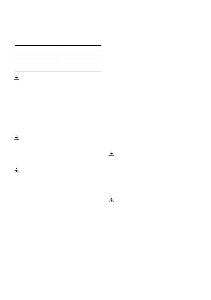
Zapoznaj si z tabel i wybierz waciw prdko
cicia obrabianego elementu. Ta waciwa prdko
moe jednak ni si w zalenoci od rodzaju
elementu i jego gruboci. Generalnie wiksze prdkoci
pozwalaj ci obrabiane elementy szybciej, ale
wówczas skróceniu ulegnie okres uytkowania tarczy.
Cięty element Numer na pokrętle regulacyjnym
Drewno 5 - 6
Stal miękka 3 - 6
Stal nierdzewna 3 - 4
Aluminium 3 - 6
Tworzywa sztuczne 1 - 4
006583
UWAGA:
Jeeli narzdzie bdzie uywane nieprzerwanie
przez duszy okres czasu przy maych
prdkociach, wówczas dojdzie do przecienia i
przegrzania silnika.
Pokrto regulacji prdkoci mona maksymalnie
obróci do pozycji 6 i z powrotem do pozycji 1. Nie
wolno próbowa obci go na si poza pozycj 6
lub 1, gdy funkcja regulacji prdkoci moe
przesta dziaa.
MONTA
UWAGA:
Przed wykonywaniem jakichkolwiek czynnoci na
elektronarzdziu naley upewni si, czy jest ono
wyczone i nie podczone do sieci.
Zakadanie lub zdejmowanie tarczy
Rys.4
UWAGA:
Naley zawsze oczyci brzeszczot i/lub zacisk
brzeszczotu z wiórów i innych zanieczyszcze.
Niestosowanie si do tej zasady moe prowadzi
do zbyt sabego dokrcenia brzeszczotu, a w
rezultacie do powanego wypadku.
Zaraz po zakoczeniu pracy nie wolno dotyka
brzeszczotu ani citego elementu. Mog one by
bardzo gorce i dotknicie grozi poparzeniem
skóry.
Zawsze naley pewnie zamocowa ostrze.
Niewystarczajce zamocowanie ostrza moe
spowodowa jego pknicie bd powane
obraenia ciaa.
Naley uywa tylko brzeszczotu typu B.
Uywanie brzeszczotów innych ni typ B moe
spowodowa niewystarczajce dokrcenie, a tym
samym stwarza ryzyko powanych obrae.
Aby zainstalowa ostrze, naley poluni sworze
znajdujcy si na uchwycie ostrza uywajc klucza
szecioktnego przeciwnie do kierunku ruchu
wskawek zegara.
Naley umieci ostrze zwrócone zbami do przodu w
uchwyt ostrza tak gboko, jak to tylko moliwe. Naley
upewni si, e tylna krawd ostrza mieci si w waku.
Nastpnie naley zacisn sworze zgodnie z
kierunkiem ruchu wskazówek zegara, aby pewnie
zamocowa ostrze.
Rys.5
Aby zdemontowa brzeszczot, naley w odwrotnej
kolejnoci wykona procedur montau.
UWAGA:
Raz od czasu naoliwi waek.
Przechowywanie klucza szecioktnego
Rys.6
Klucz szecioktny, gdy nie jest uywany, naley
przechowywa zgodnie z rysunkiem, aby nie zapodzia
si.
Regulacja waka (dla modelu 4326/4327)
Rys.7
Poluni sworze znajdujcy si z tyu podstawy za
pomoc klucza szecioktnego. Usun ustalacz, tak
aby waek styka si delikatnie z ostrzem. Nastpnie
przykrci sworze, aby umocowa podstaw oraz
ustalacz.
UWAGA:
Raz od czasu naoliwi waek.
Osona przeciwpyowa
Rys.8
UWAGA:
Zawsze naley zakada okulary ochronne nawet,
gdy pracuje si z narzdziem, w którym pokrywa
przeciwpyowa jest opuszczona.
Opuci pokryw przeciwpyow, aby unikn
przemieszczania si ubytków. Jednake, przed ciciem
ukonym podnie cakowicie pokryw przeciwpyow.
DZIAANIE
UWAGA:
Zawsze naley trzyma podstaw pasko na
elemencie obróbki. Niedostosowanie si do tej
zasady moe spowodowa pknicie ostrza a w
rezultacie doprowadzi do powanych obrae
ciaa.
Przy ciciu wzdu linii krzywych lub wyrzynania
przesuwa urzdzenie w kierunku cicia.
Nadmierne napieranie na urzdzenie moe
spowodowa powstanie krzywych ci i pknicie
ostrza.
Wcz pilark i zanim opucisz j, odczekaj, a tarcza
osignie swoj maksymaln prdko obrotow.
Nastpnie przyoy podstaw pasko do elementu
obróbki i delikatnie przesuwa urzdzenie do przodu
wzdu uprzednio zaznaczonej linii cicia.
Rys.9
  • Page 1 1
  • Page 2 2
  • Page 3 3
  • Page 4 4
  • Page 5 5
  • Page 6 6
  • Page 7 7
  • Page 8 8
  • Page 9 9
  • Page 10 10
  • Page 11 11
  • Page 12 12
  • Page 13 13
  • Page 14 14
  • Page 15 15
  • Page 16 16
  • Page 17 17
  • Page 18 18
  • Page 19 19
  • Page 20 20
  • Page 21 21
  • Page 22 22
  • Page 23 23
  • Page 24 24
  • Page 25 25
  • Page 26 26
  • Page 27 27
  • Page 28 28
  • Page 29 29
  • Page 30 30
  • Page 31 31
  • Page 32 32
  • Page 33 33
  • Page 34 34
  • Page 35 35
  • Page 36 36
  • Page 37 37
  • Page 38 38
  • Page 39 39
  • Page 40 40
  • Page 41 41
  • Page 42 42
  • Page 43 43
  • Page 44 44
  • Page 45 45
  • Page 46 46
  • Page 47 47
  • Page 48 48
  • Page 49 49
  • Page 50 50
  • Page 51 51
  • Page 52 52
  • Page 53 53
  • Page 54 54
  • Page 55 55
  • Page 56 56
  • Page 57 57
  • Page 58 58
  • Page 59 59
  • Page 60 60

Makita 4326 Instrukcja obsługi

Kategoria
Wyrzynarki akumulatorowe
Typ
Instrukcja obsługi
Ten podręcznik jest również odpowiedni dla