
1
GüterwagenGüterwagen
Elektrolok • Electric locomotive • Locomotive
électrique • Elektrická lokomotiva • Elektrowóz
BR 189
www.tillig.com www.facebook.com/tilligbahn 367068 / 21.02.2018
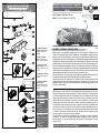
(DE) Das Modell ist eine maßstäbliche Nachbildung der BR 189 mit authentischer Farbgebung und De-
koration. Die Stromabnahme erfolgt von allen Radsätzen auf Oberleitungsbetrieb. Angetrieben wird das
Modell von einem Motor über alle Radsätze, wobei zwei davon mit je einem Haftreifen versehen sind. Zwei
Schwungmassen sorgen für einen ausgeglichenen Lauf. Der Lichtwechsel erfolgt automatisch entsprechend
der Fahrtrichtung. Vorbildentsprechend werden für das Frontlicht kaltweiße LED verwendet. Die Ausstattung
der Dachausrüstung ist sehr aufwendig mit vielen einzeln angesetzten Teilen vollständig nachgebildet. Es
kommen drei verschiedene Pantographen zum Einsatz. Die beiden mittleren werden für das Fahren unter
Gleichstrom genutzt. Beim Vorbild haben sie unterschiedliche Schleieistenmaterialien für die unterschiedli-
chen Bahnsysteme. Die beiden äußeren werden für das Wechselstromsystem verwendet. Dabei entspricht
einer der beiden dem schmaleren Zick-Zack nach Schweizer / Französischer Norm.
Das Öffnen des Modells ist durch Spreizen des Oberteiles und Abheben desselben nach oben möglich. Die
Rastnasen des Unterteils ragen in die Trittstufenmulden der Führerstandsaufstiege hinein.
Das Modell erreicht nach einer Einlaufzeit von ca. 20 Minuten in beide Fahrtrichtungen seine optimalen
Fahreigenschaften. Ab Werk ist das Modell ausreichend gefettet. Ein Nachfetten oder -ölen mit harz- und
säurefreiem Fett oder Öl ist erst nach ca. 100 Betriebsstunden zu empfehlen. Dazu geeignetes Fett ist unter
TILLIG Art.-Nr. 08973 erhältlich.
(GB) The model is a to-scale reproduction of the BR 189 with authentic colouring and decoration. The current
is drawn from all the wheel sets via catenary operation. The model is driven by motor via wheel sets whereby
two of them are equipped with a traction tyre. Two ywheels ensure it runs in a balanced manner. The light
change is performed automatically in accordance with the direction of travel. In accordance with the model,
cold white LEDs are used for the headlight. The equipment of the roof installations is very complex with many
individually applied parts that have been completely recreated. Three different pantographs are used. The
two middle ones are used for driving under direct current. In the case of the model they have different contact
strip materials for the different track systems. The two external ones are used for the alternating current sys-
tem. In this case one of the two corresponds to the narrower zigzag according to the Swiss/French standard.
It is possible to open the model by spreading the upper part and lifting it upwards. The latching lugs of the
lower part protrude into the foot steps of the driver's cab ladders.
The model achieves its optimum driving characteristics after a running-in time of approx. 20 minutes in
both directions. The model comes sufciently greased at delivery. Regreasing or oiling with acid-free and
resin-free lubricant or oil is only necessary after approx. 100 operating hours. Suitable grease is TILLIG with
the Item no. 08973.
8
Art.-Nr. / Item no. / Réf. / Art.-č. / Nr art.
02485 – E 189 914 „Lokomotion“, D-LM, Ep. VI
620
162
(DE) Technische Änderungen
vorbehalten! Bei Reklamationen
wenden Sie sich bitte an Ihren
Fachhändler.
(GB) Subject to technical
changes! Please contact your
dealer if you have any complaints.
(FR) Sous réserve de modi-
cations techniques! Pour toute
réclamation, adressez-vous à votre
revendeur.
(CZ) Technické změny vyhrazeny!
Při reklamaci se obraťte na svého
obchodníka.
(PL) Zastrzega się możliwość
zmian technicznych!
W przypadku reklamacji prosimy
zgłaszać się do specjalistycznego
sprzedawcy.
TILLIG
Modellbahnen
GmbH
Promenade 1
01855 Sebnitz
Tel.: +49 (0)35971 / 903-45
Fax: +49 (0)35971 / 903-19
(DE) Hotline Kundendienst
(GB) Hotline customer service
(FR) Services à la clientèle Hotline
(CZ) Hotline Zákaznické služby
(PL) Biuro Obsługi Klienta:
www.tillig.com/
Service_Hotline.html
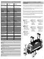
ERSATZTEILLISTE SPARE PARTS LIST
LISTE DES PIÈCES DE RECHANGE
4
8
10
19
11
15
14
4
5
9
13
7
16
3
1
2
6
18
17
22
24
23
3
12
20
21
25
26
27

2
(FR) Le modèle est la reproduction à l’échelle de la BR 189 avec couleur et décoration authentiques corres-
pondantes. Le courant est absorbé par tous les essieux montés en mode l aérien. Le modèle est entraîné
par un moteur via tous les essieux, dont deux sont pourvus respectivement d’un bandage adhérant. Deux
volants d’inertie assurent une marche régulière. Le changement de lumière s’effectue automatiquement en
fonction du sens de la marche. Conformément à l’exemple, on utilise des LED blanc froid pour la lumière
frontale. L’équipement de toit a été reproduit intégralement avec un grand nombre de pièces ajoutées. Trois
pantographes différents sont utilisés. Les deux centraux sont utilisés pour la marche en courant continu. Sur
l’exemple, ils possèdent des matériaux de frotteur différents pour les systèmes de voies différents. Les deux
extérieurs sont utilisés pour le courant alternatif. Ici, l’un des deux correspond au zigzag plus étroit selon la
norme suisse/française.
L’ouverture du modèle s’effectue en écartant la partie supérieure et en la soulevant ensuite. Les taquets de la
partie inférieure pénètrent dans les cavités de la marche de la montée à la cabine conducteur.
Après une période de rodage d’env. 20 minutes dans les deux sens de marche, le modèle atteint ses
caractéristiques optimales de marche. Le modèle est sufsamment graissé à l’usine. Nous recommandons
de regraisser ou rehuiler avec une graisse ou une huile exempte de résine et d’acide après env. 100 heures
de service. La graisse adaptée est disponible chez Tillig, réf.: 08973.
(CZ) Model je napodobenina BR 189 v přesném měřítku včetně autentického zbarvení a dekorací. Odběr
proudu je zajištěn všemi dvojkolími v trolejovém provozu. Pohon modelu zajišťuje motor pohánějící všechna
dvojkolí, dvě z nich jsou osazena adhezními nákolky. Dva setrvačníky zajišťují rovnoměrný chod. Přepínání
světel probíhá automaticky podle směru jízdy. Pro čelní osvětlení se používají světelné diody se studeným
bílým světlem podle předlohy. Vybavení střešních agregátů je velmi složité a je kompletně napodobeno
mnoha nasazenými díly. Používají se tři různé pantografy. Dva prostřední se používají pro jízdu na stej-
nosměrný proud. U předlohy jsou použity různé materiály sběrací lišty pro různé železniční systémy. Dva
vnější se používají na střídavý proud. Jeden z nich odpovídá úzkému střídavému systému podle švýcarské/
francouzské normy.
Otevření modelu se provádí rozevřením horní části a jejím zvednutím nahoru. Aretační západky dolní části
zapadají do výstupků stupátek schodů ke stanovišti strojvedoucího.
Po záběhu trvajícím zhruba 20 minut v obou směrech dosáhne model svých optimálních jízdních vlastností. Z
výroby je model již dostatečně namazán. Domazání nebo olejování mazacím tukem nebo olejem bez obsahu
pryskyřic a kyselin se doporučuje teprve po cca 100 provozních hodinách. K tomu účelu je vhodný mazací
tuk TILLIG Art.-č. 08973.
(PL) Model to odpowiednia do skali kopia BR 189 o autentycznej kolorystyce i dekoracji. Pobór prądu nastę-
puje ze wszystkich zespołów kół dla eksploatacji za pomocą przewodu napowietrznego. Model napędzany
jest przez silnik poprzez wszystkie zespoły kół, przy czym dwa z nich wyposażone są każdy w jedną oponę
przyczepną. Dwie masy zamachowe zapewniają wyrównany bieg. Światła zmieniane są automatycznie
odpowiednio do kierunku jazdy. Odpowiednio do wzorca jako światła przednie zastosowano diody LED o
zimnym świetle. Wyposażenie dachu zostało pracowicie skopiowane w całości z wszelkimi szczegółami.
Stosowane są trzy różne pantografy. Dwa środkowe używane są do jazdy z prądem stałym. We wzorcu
ich płytki ślizgowe wykonane są z różnych materiałów odpowiednio do rożnych systemów kolejowych. Dwa
zewnętrzne używane są do jazdy z prądem zmiennym. Jeden z nich odpowiada przy tym węższemu zygza-
kowi według normy szwajcarskiej / francuskiej.
Model można otworzyć przez rozszerzenie części górnej na boki i pociągnięcie jej w górę. Noski zatrzasków
części dolnej wystają na wgłębienia schodków drabinki prowadzącej do stanowiska maszynisty.
Model po ok. 20 minutach docierania osiąga optymalne właściwości jezdne w obu kierunkach jazdy. Model
został dostatecznie nasmarowany przez producenta. Powtórne smarowanie lub oliwienie za pomocą wolne-
go od żywic i kwasów smaru lub oleju zaleca się dopiero po ok. 100 godzinach eksploatacji. Odpowiedni do
tego celu smar dostępny jest pod Nr. art. TILLIG 08973.
7
1
2
3
4
5
6
7
8
9
10
11
12
13
14
15
16
17
18
19
20
21
22
23
24
25
26
27
Art.-Nr.
Item no.
Nr art.
393220
202924
200455
301734
200366
330049
300672
321030
301782
351291
393380
202123
204131
202121
202115
301731
301732
323550
307250
318660
303040
202126
202116
202117
202059
202061
301753
227445
204132
(GB) Not suitable for young people under the age of 14 due to the small parts that can be removed and swallowed and risk of injury due to
function-related sharp corners and edges. When this product comes to the end of its useful life, you may not dispose of it in the ordinary domestic waste
but must take it to your local collection point for recycling electrical and electronic equipment. If you don’t know the location of your nearest disposal centre
please ask your retailer or the local council ofce.
Tento produkt nesmí být na konci svého
užívání zlikvidován jako běžný domovní odpad, ale musí být zlikvidován např. ve sběrném dvoře. Prosím, zeptejte se vašeho obchodníka, popř. na svém
obecním úřadě o vhodném způsobu likvidace.
Produkty oznaczone przekreślonym pojemnikiem po zakończeniu użytkowania nie mogą być usuwane
razem z normalnymi odpadami domowymi, lecz muszą być przekazywane do punktu zbierania i recyklingu urządzeń elektrycznych i elektronicznych. Dzięki recyklingowi
pomagają Państwo skutecznie chronić środowisko naturalne. Prosimy zwrócić się do specjalistycznego sklepu lub do odpowiedniego urzędu w Państwa okolicy, aby dowie-
dzieć się, gdzie jest najbliższy punkt recyklingu urządzeń elektrycznych i elektronicznych.
(FR) Ne convient pas aux enfants de moins de 14 ans en raison de pièces pouvant être retirées et avalées et du risque de blessure en raison de
coins et de bords vifs dus au fonctionnement. À la n de sa durée de vie, ne pas éliminer ce produit avec les déchets ménagers mais le remettre à un
point de collecte pour le recyclage d’appareils électriques et électroniques. Veuillez vous adresser à votre revendeur ou à l’administration communale pour
connaître les points d’élimination compétents.
(DE) Nicht geeignet für Kinder unter 14 Jahren wegen abnehmbarer und verschluckbarer Kleinteile und Verletzungsgefahr durch funktionsbedingte
scharfe Ecken und Kanten. Dieses Produkt darf am Ende seiner Nutzungsdauer nicht über den normalen Hausmüll entsorgt werden, sondern muss an einem
Sammelpunkt für das Recycling von elektrischen und elektronischen Geräten abgegeben werden. Bitte fragen Sie bei Ihrem Händler oder der Gemeindever-
waltung nach der zuständigen Entsorgungsstelle.
(PL) Nazwa
Śruba z łbem (E) PT 1,8x4
Płytka drukowana, zmontowana
Wał, zmontowany
Wał kardana
Silnik, kompletny
Hak sprzęgu
Główka sprzęgu
Uchwyt
Dyszel sprzęgu
Ostoja
Spiralna sprężyna naciskowa
Budka maszynisty, zmontowana
Fartuch, zmontowana
Skrzynia akumulatorowa, zmontowana
Wózek, kompletny
Wózek, część A
Wózek, część B
Koło zębate z9
Koło zębate z19
Koło zębate z20/z13
Koło zębate z15
Wykładzina wózka
Sprężyna prądowa, prawo, kompletny
Sprężyna prądowa, lewo, kompletny
Zestaw kołowy napędowy
z tarcza hamulcowa
Zestaw kołowy napędowy z opaską przyczepną
Zderzak
Opaski przyczepne Dm 10,5 (bez rys.)
Części Dodatkowe (rys. strona 3)
(CZ) Popis
Zápustný šroub 1,8x4,3 (E) PT 1,8x4
Deska s plošnými spoji , namontovat
Unašeč se šnekem, namontovat
Kardan
Motor, kompletní
Spojkový hák
Hlava spojky
Uchycení
Oj spřáhla
Rám
Spirálová pružina
Kabina strojvedoucího, namontovat
Zástěra, namontovat
Bateriová skříň, namontovat
Otočný podvozek, kompletní
Otočný podvozek, část A
Otočný podvozek, část B
Ozubené kolo z9
Ozubené kolo z19
Ozubené kolo z20/z13
Ozubené kolo z15
Zakrytování otočného podvozku
Proudová pružina pravý, kompletní
Proudová pružina levý, kompletní
Kola s ozubeným převodem
s brzdový kotouč
Kola s ozubeným převodem s bandáží
Nárazník
Bandáže Dm 10,5 (bez zobrazení)
Příslušenství (zobrazení strana 3)

B
B
D
C
E
G
FF
A
36
(DE) ACHTUNG! Die Lok-Betriebsnummern der Artikel wechseln unter Umständen bei Neuproduktion. Ersatzteile zu den
Art.-Nr. tragen die jeweils in der Produktion bendlichen Betriebsnummern. Ersatzteile mit älteren Betriebsnummern nur
solange Vorrat reicht.
(GB) PLEASE NOTE! The locomotive operating numbers of the articles can potentially change in the event of new production
runs. Spare parts for the article number bear the operating numbers that are respectively in production. Spare parts with older
operating numbers are only available while stocks last.
(FR) ATTENTION! Les numéros d’exploitation de locomotives des articles changent parfois lors d’une nouvelle production.
Les pièces de rechange relatives au n° art. portent respectivement les numéros d’exploitation se trouvant en production.
Pièces de rechange avec des numéros d’exploitation plus anciens jusqu’à rupture du stock.
(CZ) POZOR! Provozní číslo lokomotivy u tohoto artiklu se může změnit podle okolností nové výroby. Náhradní díly jsou k
dispozici k tomuto kat. číslu, které je právě ve výrobě. Náhradní díly Ke starším typům jsou pouze do té doby, dokud vystačí
skladové zásoby.
(PL) UWAGA! Numery części lokomotywy mogą się zmieniać wraz z nową produkcją modelu. Części zamienne dla danego
numeru artykułu za każdym razem mają numery przyjęte z produkcji. Części zamienne ze starymi numerami części są
dostępne tylko do wyczerpania zapasu.
!
!
!
!
!
ZURÜSTTEILE • ACCESSORY PARTS • PIÈCES D’ÉQUIPEMENT •
(DE) Dem Modell liegen zur weiteren Detaillierung Zurüstteile bei, die unter Beachtung des Einsatzes des
Modells angebracht werden können. Die Teile sollten mit einem Tropfen Sekundenkleber gesichert werden.
(GB) The model contains additional detailing sets that can be added depending on the use the model is
put to. The parts should be secured with a drop of superglue.
(FR) Pour apporter plus de détails au modèle, quelques accessoires sont joints, ils peuvent être installés
conformément à l’utilisation du modèle. Il est conseillé de xer les pièces avec une goutte de colle rapide.
(CZ) Pro rozšíření detailů je k modelu přibaleno příslušenství, které lze volitelně nasadit podle použití
modelu. Komponenty připevněte kapkou vteřinového lepidla.
(PL) Dla wyposażenia modelu w kolejne detale załączono dodatkowe akcesoria, które można zamonto-
wać zależnie od zastosowania. Części należy umocować za pomocą kropli kleju błyskawicznego.
C(DE) Griffstange, ach
(GB) Handle bar, at
(FR) Barre de maintien, plat
(CZ) Madlo, plochý
(PL) Poręcz, płaski
B(DE) Bremsschläuche
(GB) Brake hoses
(FR) Tuyaux de frein
(CZ) Vzduchové hadice
(PL) Przewody hamulcowe
D(DE) Griffstange, links
(GB) Handle bar, left
(FR) Barre de maintien,
gauche
(CZ) Madlo, levý
(PL) Poręcz, lewo
E(DE) Griffstange, rechts
(GB) Handle bar, right
(FR) Barre de maintien,
droite
(CZ) Madlo, pravý
(PL) Poręcz, prawo
(DE) Kuppelhaken
(GB) Coupling
(FR) Crochet d’attelage hook
(CZ) Hák spřáhla
(PL) Hak cięgłowy
AF(DE) Griffstange; 2,3 mm
(GB) Handle bar; 2,3 mm
(FR) Barre de maintien;
2,3 mm
(CZ) Madlo; 2,3 mm
(PL) Poręcz; 2,3 mm
G(DE) Griffstange; 4,5 mm
(GB) Handle bar; 4,5 mm
(FR) Barre de maintien;
4,5 mm
(CZ) Madlo; 4,5 mm
(PL) Poręcz; 4,5 mm
ERSATZTEILLISTE SPARE PARTS LIST LISTE DES PIÈCES DE RECHANGE
(FR) Description
Vis à tête conique (E) PT 1,8x4
Carte de circuits imprimé, montée
Tige, montée
Arbre Cardan
Moteur, complète
Crochet d’attelage
Tête d’attelage
Logement
Barre d’attelage
Châssis
Ressort de pression en spirale
Cabine du conducteur, montée
Tablier, montée
Boîte de batterie, montée
Bogie, complète
Bogie, partie A
Bogie, partie B
Roue dentée d9
Roue dentée d19
Roue dentée d20/d13
Roue dentée d15
Habillage de bogie
Ressort de pantographe, droite,compl.
Ressort de pantographe, gauche,compl.
Essieu moteur avec disque de frein
Essieu moteur avec bandage adhérant
Tampon
Bandage adhérant Dm 10,5 (sans illustr.)
Pièces d’équipement (illustr. page 3)
(GB) Description
Countersunk screw (E) PT 1,8x4
Circuit board, mounted
Shaft, mounted
Cardan shaft
Motor, complete
Clutch hook
Coupling head
Pocket
Coupler drawbar
Frame
Spiral compression spring
Driver's cab, mounted
Apron, mounted
Battery box, mounted
Bogie, complete
Bogie, part A
Bogie, part B
Gear wheel 9 teeth
Gear wheel 19 teeth
Gear wheel 20/13 teeth
Gear wheel 15 teeth
Bogie cover
Pantograph, right, complete
Pantograph left, complete
Driving wheel set with brake disc
Driving wheel set w. traction tyres
Buffer
Traction tyre Dm 10,5 (w/o illustr.)
Accessory parts (illustr. page 3)
(DE) Bezeichnung
Senkschraube (E) PT 1,8x4
Leiterplatte, mont.
Schaft, mont.
Kardanwelle
Motor, vollst.
Kupplungshaken
Kupplungskopf
Aufnahme
Kupplungsdeichsel
Rahmen
Spiraldruckfeder
Führerstand, mont.
Schürze, mont.
Batteriekasten, mont.
Drehgestell, vollst.
Drehgestell, Teil A
Drehgestell, Teil B
Zahnrad z 9
Zahnrad z 19
Zahnrad z 20/13
Zahnrad z 15
Drehgestellverkeidung
Stromfeder, re., vollst.
Stromfeder, li., vollst.
Treibradsatz mit
Bremsscheibe
Treibradsatz mit Haftreifen
Puffer
Haftreifen Dm 10,5 (o. Abb.)
Zurüstteile (Abb. S.3)
1
2
3
4
5
6
7
8
9
10
11
12
13
14
15
16
17
18
19
20
21
22
23
24
25
26
27

54
(FR) Pour la numérisation, il existe une interface PluX12 dans le modèle. Nous recommandons l’utilisation d’un décodeur PluX12
d’Uhlenbrock (réf. TILLIG 66034). Pour monter le décodeur, enlever la partie supérieure conformément aux instructions de la page 2
« Le modèle ». L’interface du décodeur se trouve sur le côté dans un creux du châssis. Si le kit anti-parasite est complètement retiré
avec la carte de circuits imprimés d’adaptateur à 12 pôles (illustr. 3), un décodeur PluX12 peut être monté (illustr.3). Si seul le kit carte
de circuits imprimés d’adaptateur est retiré, un décodeur à 6 pôles selon NEM 651 peut être inséré (illustr. 1).
Si le décodeur PluX 12 est utilisé, il est possible en mode numérique de commuter séparément la lumière à longue portée. Le feu
arrière de la locomotive peut également être éteint séparément ou commuté sans lumière frontale. Il est possible d’installer en plus un
haut-parleur rectangulaire dans la zone de la reproduction du transformateur. Le raccordement du haut-parleur s’effectue aux deux
plots de soudure sur la carte de circuits imprimés principale identiés par LSA et LSB.
Avant la mise en service de la locomotive, contrôler la tension à la centrale numérique. Pour l’utilisation de voitures de
largeur de voie TT, H0, H0e et H0m, une tension numérique de max. 14 V est recommandée. Des tensions plus élevées
se traduisent par une usure accrue des moteurs. Les défauts de décodeur (par sur-charge) dus à cette cause ne sont pas
couverts par la garantie.
F0 lumière éteinte:
F0 éteint + F1 allumé = lumière rouge à la cabine conducteur 1
indépendamment du sens de la marche
F0 éteint + F2 allumé = lumière rouge à la cabine conducteur 2
indépendamment du sens de la marche
F0 éteint + F3 allumé = opération de manœuvre avec lumière
de manœuvre
F0 éteint + F4 allumé = opération de manœuvre sans lumière
de manœuvre
F0 lumière allumée: Lumière avant blanche/arrière rouge
change avec le sens de marche
F0 allumé + F1 allumé = lumière à longue portée allumée,
selon le sens de la marche
F0 allumé +F2 allumé = feu arrière (rouge) éteint,
selon le sens de la marche
F0 allumé + F3 allumé = opération de manœuvre avec
lumière de manœuvre
(CZ) Pro digitalizaci je model opatřen rozhraním PluX12. Doporučujeme použití dekodéru Plux12 rmy Uhlenbrock (TILLIG art.č.
66034). Pro montáž dekodéru je nutné sejmout karoserii dle návodu „Modell“ na straně 2. Po straně ve vybrání rámu se nachází roz-
hraní pro dekodér. Po kompletním odstranění odrušovací sady s 12-pólovou deskou adaptéru (obr. 3) lze namontovat dekodér PluX12
(obr. 2). V případě odstranění pouze odrušovací sady lze zasunout 6-pólový dekodér dle NEM 651 (obr.1).
V případě použití dekodéru PluX12 je možné v digitálním provozu zapínat dálkové světlo samostatně. Koncové světlo lokomotivy lze
rovněž samostatně vypínat nebo zapínat bez čelního světla. Dodatečná montáž hranatého reproduktoru je možná v místě napod-
obení transformátoru. Připojení reproduktoru se provádí na dvě letovací patice označené LSA a LSB na hlavní desce.
F0 vyp+F1 zap = červené světlo na stanovišti strojvedoucího 1,
nezávisle na směru jízdy
F0 vyp+F2 zap = červené světlo na stanovišti strojvedoucího 2,
nezávisle na směru jízdy
F0 vyp+F3 zap = posunování s posunovacím světlem
F0 vyp+F4 zap = posunování bez posunovacího světla
F0 zap+F1 zap = zapnuté dálkové světlo,
v závislosti na směru jízdy
F0 zap+F2 zap = vypnout koncové světlo (červené),
v závislosti na směru jízdy
F0 zap+F3 zap = posunování s posunovacím světlem
(PL) Model jest wyposażony w złącze PluX12 do cyfryzacji. Zalecamy stosowanie dekodera PluX12 rmy Uhlenbrock (TILLIG nr art.
66034). W celu montażu dekodera należy zdjąć część górną zgodnie z instrukcją na str. 2 "Model". Złącze dekodera znajduje się
po boku we wgłębieniu ramy. Dekoder PluX12 można zamontować (rys. 2) po zdjęciu zespołu przeciwzakłóceniowego razem z 12-
biegunową płytką drukowaną adaptera (rys.3). Jeżeli zdejmie się tylko zespół zakłóceniowy, można zamontować 6-biegunowy deko-
der wg NEM 651 (rys.1).
W przypadku użycia dekodera PluX12, w eksploatacji cyfrowej istnieje możliwość osobnego przełączania świateł długich. Również
światło tylne spalinowozu można osobno wyłączać lub włączać je bez włączania świateł przednich. Dodatkowy montaż prostokątnego
głośnika jest możliwy w obrębie kopii transformatora. Głośnik podłącza się za pomocą dwóch kłębków do lutowania, oznaczonych
jako LSA i LSB, znajdujących się na głównej płytce drukowanej.
F0 vyp+F1 zap = červené světlo na stanovišti strojvedoucího 1,
nezávisle na směru jízdy
F0 vyp+F2 zap = červené světlo na stanovišti strojvedoucího 2,
nezávisle na směru jízdy
F0 vyp+F3 zap = posunování s posunovacím světlem
F0 vyp+F4 zap = posunování bez posunovacího světla
F0 zap+F1 zap = zapnuté dálkové světlo,
v závislosti na směru jízdy
F0 zap+F2 zap = vypnout koncové světlo (červené),
v závislosti na směru jízdy
F0 zap+F3 zap = posunování s posunovacím světlem
!
!
!
DIGITALISIERUNG • DIGITALIZATION • NUMÉRISATION • DIGITALIZACE • DIGITALIZACJA
(DE) Für eine Digitalisierung gibt es im Modell eine PluX12 Schnitt-
stelle. Wir empfehlen die Verwendung eines Decoders PluX12 von
Uhlenbrock (TILLIG Art.-Nr. 66034).
Zum Einbau des Decoders ist das Oberteil entsprechend der Anlei-
tung auf Seite 1 „Das Modell“ abzunehmen. Seitlich in einer Rah-
menaussparung bendet sich die Decoderschnittstelle. Wird der
Entstörsatz komplett mit der 12-poligen Adapterleiterplatte abge-
zogen (Abb.3), kann ein PluX12-Decoder montiert werden (Abb.2).
Wird nur der Entstörsatz abgezogen, kann ein 6-poliger Decoder
nach NEM 651 eingesteckt werden (Abb.1).
Wird der PluX12-Decoder benutzt, besteht die Möglichkeit, im
Digitalbetrieb das Fernlicht separat zu schalten. Das Schlusslicht
der Lok kann ebenfalls separat ab- oder ohne Frontlicht zugeschal-
tet werden. Der zusätzliche Einbau eines rechteckigen Lautspre-
chers ist im Bereich der Trafonachbildung möglich. Der Anschluss
des Lautsprechers erfolgt an den zwei mit LSA und LSB gekenn-
zeichneten Lötpäds auf der Hauptleiterplatte.
F0 Licht aus:
F0 aus+F1 an = Licht rot an Führerstand 1,
unabhängig von der Fahrtrichtung
F0 aus+F2 an = Licht rot an Führerstand 2,
unabhängig von der Fahrtrichtung
F0 aus+F3 an = Rangiergang mit Rangierlicht
F0 aus+F4 an = Rangiergang ohne Rangierlicht
F0 Licht an: Licht vorne weiß/hinten rot,
wechselnd mit Fahrtrichtung
F0 an+F1 an = Fernlicht an, fahrtrichtungsabhängig
F0 an+F2 an = Schlussleuchte (rot) aus, fahrtrichtungsabhängig
F0 an+F3 an = Rangiergang mit Rangierlicht
Bitte prüfen Sie vor Inbetriebnahme der Lok die Spannung
an Ihrer Digitalzentrale. Für den Betrieb von Fahrzeugen
der Spurweiten TT, H0, H0e und H0m wird eine Digitalspannung
von max. 14 Volt empfohlen. Höhere Spannungen führen zu
einem höheren Verschleiß der Motoren. Decoderdefekte (durch
Überlast), die durch diese Ursache entstehen, fallen nicht unter
die Gewährleistung.
(GB) The model has a PluX12 connector for digital operation. We
recommend using the Uhlenbrock PluX12 decoder (TILLIG Item no.
66034).
Remove the top part as per instructions on page 1, “The model”, to install
the decoder. The decoder interface is located at the side in the frame
recess. A PluX12 decoder (Fig.2) can be installed once the interference
suppression set including the 12-pin adapter circuit board (Fig.3) is
fully removed. If only the interference suppression set is unplugged, a
6-pole NEM 651 decoder can be plugged in. (Fig.1).
If the PluX12 decoder is used while in digital mode, it is possible to turn on the full beam autonomously. Also the locomotive rear light
can be turned off individually or turned on without the front light is turned on. An additional rectangular loudspeaker can be installed in
the area of the transformer replica. The loudspeaker is connected to the two soldering pads marked LSA and LSB on the main circuit
board.
Please check the voltage at your digital centre before starting the locomotive. A digital voltage of max. 14 Volt is
recommended for the operation of vehicles with the track widths TT, H0, H0e and H0m. Higher voltages result in higher
motor wear out. Consequently, decoder malfunctions (due to overload) arising as a result are not covered by the warranty.
F0 Light off:
F0 off+F1 on = Driver’s cab light 1 is red,
independently of the direction of travel
F0 off+F2 on = Driver’s cab light 2 is red,
independently of the direction of travel
F0 off+F3 on = Shunting mode with shunting lights
F0 off+F4 on = Shunting mode without shunting light
F0 Light on: Front light white/rear light red
changing with the direction of travel
F0 on+F1 on = Full beam on, independent of direction of travel
F0 on+F2 on = Tail light (red) off,
independent of direction of travel
F0 on+F3 on = Shunting mode with shunting lights
!
!
-
 1
1
-
 2
2
-
 3
3
-
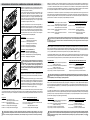 4
4


w innych językach
- Deutsch: TILLIG BAHN 02485 Bedienungsanleitung
- slovenčina: TILLIG BAHN 02485 Návod na obsluhu
- français: TILLIG BAHN 02485 Le manuel du propriétaire
Powiązane artykuły
-
TILLIG BAHN 04941 Instrukcja obsługi
-
-
-
-
-
-
-
-
-