
LDMEI1000G²
WIRELESS IN EAR MONITORING SYSTEM
USER´S MANUAL
BEDIENUNGSANLEITUNG
MANUEL D`UTILISATION
MANUAL DE USUARIO
INSTRUKCJA OBSŁUGI
MANUALE D‘ USO

CONTENTS / INHALTSVERZEICHNIS / CONTENU / CONTENIDO / TREŚĆ / CONTENUTO
ENGLISH
PREVENTIVE MEASURES 3-4
INTRODUCTION 4
SYSTEM COMPONENTS 5
CONNECTIONS, CONTROLS, AND INDICATORS 6-7
BELT PACK TRANSMITTER 7-9
SYSTEM SETUP 9-13
SETUP AND TROUBLESHOOTING 13
SPECIFICATIONS 14
MANUFACTURER´S DECLARATIONS 15
DEUTSCH
SICHERHEITSHINWEISE 16-17
EINFÜHRUNG 17
SYSTEMKOMPONENTEN 18
ANSCHLÜSSE, BEDIEN- UND ANZEIGEELEMENTE 19-20
BELT PACK SENDER 20-22
SYSTEMEINSTELLUNG 22-26
AUFSTELLUNG UND FEHLERBEHEBUNG 27
SPEZIFIKATIONEN 28
HERSTELLERERKLÄRUNGEN 29
FRANCAIS
MESURES PRÉVENTIVES 30-31
INTRODUCTION 31
COMPOSANTS DU SYSTÈME 32
CONNECTEURS, CONTRÔLES ET INDICATEURS 33-34
ÉMETTEUR DE POCHE 34-36
MENUS DE RÉGLAGE DE L‘APPAREIL 36-40
MISE EN PLACE ET EN CAS DE PROBLÈME 41
CARACTÉRISTIQUES 42
DECLARATIONS 43
ESPAÑOL
MEDIDAS DE SEGURIDAD 44-45
INTRODUCCIÓN 45
COMPONENTES DEL SISTEMA 46
CONEXIONES, CONTROLES E INDICADORES 47-48
RECEPTOR DE PETACA 48-50
CONFIGURACIÓN DEL SISTEMA 50-54
INSTALACIÓN Y RESOLUCIÓN DE PROBLEMAS 55
ESPECIFICACIONES 56
DECLARACIÓN DEL FABRICANTE 57
POLSKI
ŚRODKI OSTROŻNOŚCI 58-59
INTRODUCTION 59
ELEMENTY SYSTEMU 60
PRZYŁĄCZA, ELEMENTY OBSŁUGI I WSKAŹNIKI 61-62
PRZEŁĄCZNIK WZMACNIANIA I WYCISZANIA SYGNAŁU 62-64
USTAWIENIA SYSTEMU 64-68
USTAWIENIE I USUWANIE USTEREK 69
SPECYFIKACJA 70
DEKLARACJE PRODUCENTA 71
ITALIANO
MISURE PRECAUZIONALI 72-73
INTRODUZIONE 73
COMPONENTI DEL SISTEMA 74
CONNESSIONI, COMANDO E VISUALIZZAZIONE 75-76
INTERRUTTORE DI REGOLAZIONE DEL GUADAGNO E MUTE 76-78
IMPOSTAZIONI DI SISTEMA 78-82
MONTAGGIO ED ELIMINAZIONE DEI GUASTI 83
SPECIFICHE 84
DICHIARAZIONI DEL PRODUTTORE 85

ITALIANO
POLSKI
ESPAÑOL
FRANCAIS
DEUTSCH
ENGLISH
3
ENGLISH
YOU‘VE MADE THE RIGHT CHOICE!
We have designed this product to operate reliably over many years. LD Systems stands for this with its name and many years of experience
as a manufacturer of high-quality audio products. Please read this User‘s Manual carefully, so that you can begin making optimum use of
your LD Systems product quickly. You can find more information about LD-SYSTEMS at our Internet site WWW.LD-SYSTEMS.COM
PREVENTIVE MEASURES
1. Please read these instructions carefully.
2. Keep all information and instructions in a safe place.
3. Follow the instructions.
4. Observe all safety warnings. Never remove safety warnings or other information from the equipment.
5. Use the equipment only in the intended manner and for the intended purpose.
6. Use only sufficiently stable and compatible stands and/or mounts (for fixed installations). Make certain that wall mounts are properly installed and
secured. Make certain that the equipment is installed securely and cannot fall down.
7. During installation, observ e the applicable safety regulations for your country.
8. Never install and operate the equipment near radiators, heat registers, ovens or other sources of heat. Make certain that the equipment is
always installed so that is cooled sufficiently and cannot overheat.
9. Never place sources of ignition, e.g., burning candles, on the equipment.
10. Ventilation slits must not be blocked.
11. This appliance is designed exclusively for indoor use, do not use this equipment in the immediate vicinity of water (does not apply
to special outdoor equipment - in this case, observe the special instructions noted below). Do not expose this equipment to flammable
materials, fluids or gases.
12. Make certain that dripping or splashed water cannot enter the equipment. Do not place containers filled with liquids, such as vases or
drinking vessels, on the equipment.
13. Make certain that objects cannot fall into the device.
14. Use this equipment only with the accessories recommended and intended by the manufacturer.
15. Do not open or modify this equipment.
16. After connecting the equipment, check all cables in order to prevent damage or accidents, e.g., due to tripping hazards.
17. During transport, make certain that the equipment cannot fall down and possibly cause property damage and personal injuries.
18. If your equipment is no longer functioning properly, if fluids or objects have gotten inside the equipment or if it has been damaged in
another way, switch it off immediately and unplug it from the mains outlet (if it is a powered device). This equipment may only be repaired
by authorized, qualified personnel.
19. Clean the equipment using a dry cloth.
20. Comply with all applicable disposal laws in your country. During disposal of packaging, please separate plastic and paper/cardboard.
21. Plastic bags must be kept out of reach of children.
FOR EQUIPMENT THAT CONNECTS TO THE POWER MAINS:
22. CAUTION: If the power cord of the device is equipped with an earthing contact, then it must be connected to an outlet with a protective
ground. Never deactivate the protective ground of a power cord.
23. If the equipment has been exposed to strong fluctuations in temperature (for example, after transport), do not switch it on immediately.
Moisture and condensation could damage the equipment. Do not switch on the equipment until it has reached room temperature.
24. Before connecting the equipment to the power outlet, first verify that the mains voltage and frequency match the values specified on the
equipment. If the equipment has a voltage selection switch, connect the equipment to the power outlet only if the equipment values and the
mains power values match. If the included power cord or power adapter does not fit in your wall outlet, contact your electrician.
25. Do not step on the power cord. Make certain that the power cable does not become kinked, especially at the mains outlet and/or power
adapter and the equipment connector.
26. When connecting the equipment, make certain that the power cord or power adapter is always freely accessible. Always disconnect the
equipment from the power supply if the equipment is not in use or if you want to clean the equipment. Always unplug the power cord and
power adapter from the power outlet at the plug or adapter and not by pulling on the cord. Never touch the power cord and power adapter
with wet hands.
27. Whenever possible, avoid switching the equipment on and off in quick succession because otherwise this can shorten the useful life of
the equipment.
28. IMPORTANT INFORMATION: Replace fuses only with fuses of the same type and rating. If a fuse blows repeatedly, please contact an
authorised service centre.
29. To disconnect the equipment from the power mains completely, unplug the power cord or power adapter from the power outlet.
30. If your device is equipped with a Volex power connector, the mating Volex equipment connector must be unlocked before it can be removed.
However, this also means that the equipment can slide and fall down if the power cable is pulled, which can lead to personal injuries and/or
other damage. For this reason, always be careful when laying cables.
31. Unplug the power cord and power adapter from the power outlet if there is a risk of a lightning strike or before extended periods of disuse.
32. The device must only be installed in a voltage-free condition (disconnect the mains plug from the mains).
33. Dust and other debris inside the unit may cause damage. The unit should be regularly serviced or cleaned (no guarantee) depending on
ambient conditions (dust etc., nicotine, fog) by qualified personnel to prevent overheating and malfunction.
34. Please keep a distance of at least 0.5 m to any combustible materials.

4
DEUTSCHFRANCAIS
ESPAÑOL
ENGLISH
ITALIANO POLSKI
35. Power cables to power multiple devices must have a cross-section of at least 1.5 mm². Within the EU, the cables must correspond to
H05VV-F, or similar. Suitable cables are offered by Adam Hall. With these cables, you can connect multiple devices via the power OUT connection
to the power IN connection of an additional device. Make sure that the total current consumption of all connected devices does not exceed the
specified value on all connected devices (label on the device). Make sure to keep power cable connections as short as possible.
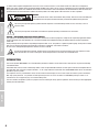
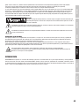
CAUTION:
To reduce the risk of electric shock, do not remove cover (or back). There are no user serviceable parts
inside. Maintenance and repairs should be exclusively carried out by qualified service personnel.
The warning triangle with lightning symbol indicates dangerous uninsulated voltage inside the unit, which may cause an
electrical shock.
The warning triangle with exclamation mark indicates important operating and maintenance instructions.
CAUTION – HIGH VOLUME LEVELS WITH AUDIO PRODUCTS!
This equipment is intended for professional use. Therefore, commercial use of this equipment is subject to the respectively applicable national
accident prevention rules and regulations. As a manufacturer, Adam Hall is obligated to notify you formally about the existence of potential
health risks.
Hearing damage due to high volume and prolonged exposure: When in use, this product is capable of producing high sound-pressure levels
(SPL) that can lead to irreversible hearing damage in performers, employees, and audience members.
For this reason, avoid prolonged exposure to volumes in excess of 90 dB.
To prevent possible hearing damage, avoid listening at high volume levels over long periods of time. Even exposure to short
bursts of loud noise can result in hearing loss. Please keep the volume constantly at a comfortable level.
INTRODUCTION
The new LD Systems MEI1000G2 is an In-Ear Monitoring-System that delivers natural sound with a large dynamic range and outstanding
crosstalk behaviour.
Switchable mono, stereo, and focus monitoring modes as well as adjustable EQ and limiter functions permit natural sound reproduction for
any application, with a frequency response of 60 Hz – 16 Hz, a high S/N ratio, and low THD. The LD MEI1000G2 allows for the simultaneous
operation of up to 5 systems.
The earphones are very comfortable to wear, and the multifunctional display on the receiver shows all relevant system information.
With high quality batteries, it is possible to attain operating times of 12 hours and more. The MEI100G2 package includes a 19“
rackmount kit and a rugged carrying case made of ABS plastic.
The use of wireless microphone systems may require a license according to country-specific regulations. Please contact your local appropriate
authority for more information.

ITALIANO
POLSKI
ESPAÑOL
FRANCAIS
DEUTSCH
ENGLISH
5
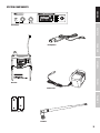
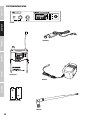
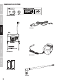
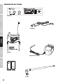
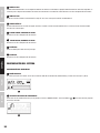
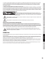
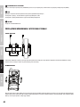
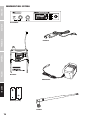
SYSTEM COMPONENTS
POWER
SET
POWER
SET
Transmitter
Headphones
Receiver
Power Pack
Batteries (2 x AA)
Antenna

6
DEUTSCHFRANCAIS
ESPAÑOL
ENGLISH
ITALIANO POLSKI
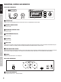
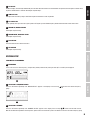
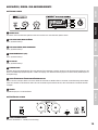
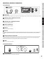
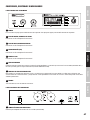
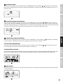
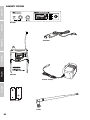
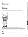
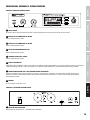
CONNECTIONS, CONTROLS AND INDICATORS
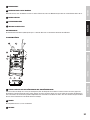
FRONT PANEL TRANSMITTER
POWER
SET
2
3
4
5
67
1
8
1
POWER BUTTON
Switch on: Press and hold button for two seconds. Switch off: Press and hold button for two seconds.
2
ARROW UP, INCREASE VALUE
See “System setup”.
3
ARROW DOWN, DECREASE VALUE
See “System setup”.
4
PROGRAMMING BUTTON (SET)
See “System setup”.
5
LC DISPLAY
See “System setup”.
6
INPUT LEVEL
Adjust the input sensitivity. In order to achieve an optimal signal to noise ratio, bring the input signal as close as possible to the 0dB indicator (level
indicator AF L and AF R in the display), without exceeding the distortion limit (PEAK segment in the level meter).
7
HEADPHONE VOLUME CONTROL
Turning the knob to the left decreases the volume; turning it to the right increases the volume. To avoid hearing damage, set the volume to minimum
before using the earphones/headphones, then slowly increase the volume. Caution: high volume can cause permanent hearing damage.
8
PHONES
Headphone output connector 6.3 mm stereo jack.
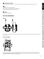
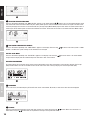
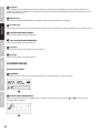
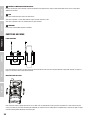
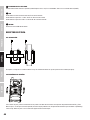
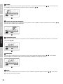
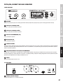
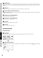
REAR PANEL TRANSMITTER
POWER
SET
2 2
3
4
1
1
LOW VOLTAGE CONNECTOR
Power supply connector for 12 - 18V DC (included).

ITALIANO
POLSKI
ESPAÑOL
FRANCAIS
DEUTSCH
ENGLISH
7
2
BALANCED INPUT LEFT/RIGHT
Left and right-hand balanced inputs (XLR / 6.3 mm jack combo). In the mono mode, only the right input (RIGHT) may be used.
3
PAD
Switchable level attenuation for high input level.
Switch in position -12 dB: Attenuation of the input signal by 12 db.
Switch in position 0 dB: No attenuation of the input signal.
4
ANTENNA
BNC antenna connector 50 Ohm.
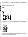
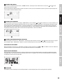
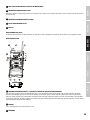
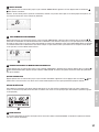
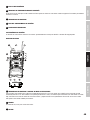
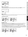
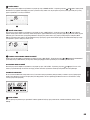
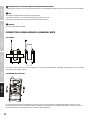
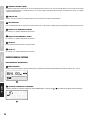
BELT PACK TRANSMITTER
BELT CLIP
Clip the receiver to your belt or a suitable strap. For optimum fit, the clip should always be pushed all the way over the belt and/or strap
(see illustration).
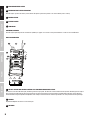
BATTERY REPLACEMENT
To replace the batteries, press gently on the marked spots on the sides of the battery cover and flip it forward. Remove the batteries,
insert two new AA-batteries (for orientation please see the illustration in the battery compartment) and close the cover. Remove the
batteries when the device is not in use for an extended period.

8
DEUTSCHFRANCAIS
ESPAÑOL
ENGLISH
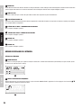
ITALIANO POLSKI
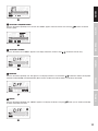
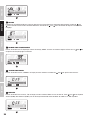
1
MICROPHONE HEAD GRILLE
2
POWER/BATTERY STATUS INDICATOR
Red LED lights up when the battery is low, Green LED lights up when the power is on and the battery status is okay.
3
POWER SWITCH
4
BATTERY COVER
5
IR WINDOW
CHANGING BATTERIES
Red LED ligThe operating time of the batteries (alkaline) is approx. 10-12 hours. Change the batteries as soon as the red LED blinks.
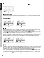
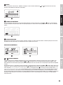
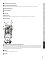
BODY PACK RECEIVER
10
1
ON/OFF SWITCH AND VOLUME CONTROL FOR EARPHONE/HEADPHONE OUTPUT
To switch on, turn the knob to the right (clockwise) past the snap-in point. To switch off, turn the knob to the left (counter clockwise) past the snap-in
point. Turning the knob to the left decreases the volume; turning it to the right increases the volume. To avoid hearing damage, set the volume to
minimum before using the earphones/headphones, then slowly increase the volume. Caution: high volume can cause permanent hearing damage.
2
PHONES
Earphone/headphone connector 3.5 mm stereo jack.
3
ANTENNA

ITALIANO
POLSKI
ESPAÑOL
FRANCAIS
DEUTSCH
ENGLISH
9
4
LC DISPLAY
Backlit LC Display. The back light automatically turns off after about 30 seconds if no control buttons are pressed; the back light is turned on when
any of the control buttons is selected. See Chapter “System Setup”.
5
LOW BATT LED
LED lights when the battery charge is low. Please replace the batteries as soon as possible.
6
RF SIGNAL LED
Lights up briefly when you switch on. Lights up when a HF signal is present. Radio frequency of both transmitter and receiver must match.
7
ARROW UP, INCREASE VALUE
See Chapter “System Setup”.
8
ARROW DOWN, DECREASE VALUE
See Chapter “System Setup”.
9
ESC-BUTTON
Press this button to return to the main menu.
10
SET BUTTON
See Chapter “System Setup”.
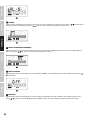
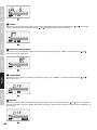
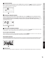
SYSTEM SETUP
TRANSMITTER PROGRAMMING
1
MAIN MENU
In the main menu the radio frequency, the operating mode (mono/stereo) and signal level (AF L and AF R) are displayed.
1
2
SELECTING A FREQUENCY GROUP
Press the SET button repeatedly until “GROUP SELECT” appears in the display. Press the keys to select the desired frequency
group.
2
3
SELECTING A CHANNEL
Press the SET button repeatedly until “CHANNEL SELECT” appears in the display. Press the keys to select the desired channel.
Note: For simultaneous operation of several systems, please make sure that all the systems use different channels on the same frequency group.

10
DEUTSCHFRANCAIS
ESPAÑOL
ENGLISH
ITALIANO POLSKI
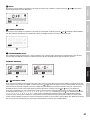
3
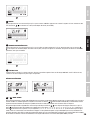
4
SELECTING THE OPERATING MODE
Press the SET button repeatedly until “MODE SELECT” appears in the display. With the buttons, you can now choose between mono
and stereo mode. Select the mono mode if only one (mono) audio signal is to be transmitted to the receiver. The signal is located on two
channels (left/right) of the receiver. In the mono mode, only the right input (INPUT RIGHT) may be used. Select the stereo mode if either a
stereo signal, or two mono signals are to be transmitted to the receiver. Please refer to the notes in the Stereo and Focus Mode chapter.
4
5
LOCK AGAINST INADVERTENT CHANGES
Press the SET button repeatedly until “LOCK SELECT” appears in the display. Press the keys to lock or unlock the system. If “LOCK
SELECT is enabled, the system settings can be viewed, but not changed.
EXIT THE SETUP MENU
Press the SET button repeatedly until “EXIT SETUP” appears in the display. Press the keys to exit the menu. If no control buttons
are pressed, the display switches automatically to the main menu after a few seconds.
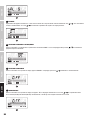
RECEIVER PROGRAMMING
To change settings on the receiver, press gently on the marked spots on the sides of the battery cover and flip it forward. The Escape
(ESC) and SET buttons are now accessible. To return to the main menu after a setting change, press the Escape button (ESC).
1
1
MAIN MENU
In the main menu, the radio frequency, RF and AF level, mono / stereo mode, EQ, limiter, as well as the lock status are displayed.
2
2
BALANCE
Adjust the volume balance between the left and right channels of a stereo signal using the buttons. When the transmitter is in
mono mode, using the buttons will set the position of the signal in the panoramic field.

ITALIANO
POLSKI
ESPAÑOL
FRANCAIS
DEUTSCH
ENGLISH
11
3
3
SELECTING A FREQUENCY GROUP
Press the SET button repeatedly on the receiver until “GROUP” appears and starts to flash. Press the keys to select the desired
frequency group.
4
4
SELECTING A CHANNEL
Press the SET button until “CHANNEL” appears in the display and flashes, and then select . the desired channel using.
5
5
EQUALIZER
Press the SET button repeatedly until “EQ” appears in the display and flashes. Use the buttons to determine whether the Equalizer
should be enabled (EQ ON), or disabled (EQ OFF). When the EQ is enabled, the treble at 10kHz is increased by around 6dB.
6
6
LIMITER
Press the SET button repeatedly until “LIMITER” appears in the display and flashes. Using the button, you can enable (Limiter ON)
or disable (limiter OFF) the limiter.
7

12
DEUTSCHFRANCAIS
ESPAÑOL
ENGLISH
ITALIANO POLSKI
7
LOCKING THE RECEIVER
Press the SET button repeatedly until “LIMITER” appears in the display and flashes. Using the button, you can enable (Limiter ON) or
disable (limiter OFF) the limiter.
8
8
BATTERY CHARGE STATUS
The charge status of the batteries is shown in four stages. In addition to the fourth stage (no bars on the battery symbol) the red LOW
BATT LED will light up next to the display. The batteries should now be replaced immediately.
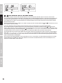
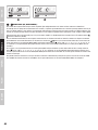
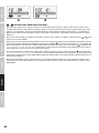
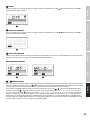
RECEIVER PROGRAMMING
1 2
1
+
2
STEREO MODE
Select the stereo mode for the transmission of a stereophonic audio signal. Press the SET button repeatedly until “FO OFF” or “FO ON”
appears in the display and flashes. Using the buttons, you can now activate the stereo mode (FO OFF). In stereo mode, the two
input signals of the transmitter can be heard through headphones (on the left and right) connected to the receiver
On the receiver, the balance between the two input signals can be set with the help of the buttons. A total of 31 levels are availa-
ble : using the button, the centre location of a stereo signal can be changed by 15 levels to the right (1-, 2-, 3-, 4-, 5-, 6-, 7-, 8-, 9-,
A-, b-, C-, d-, E-, F-) and by 15 levels to the left (-1, -2, -3, -4, -5, -6, -7, -8, -9, -A, -b, -C, -d, -E, -F). To bring the centre location of
a stereophonic audio signal to the centre of the stereo base, please select the -0- setting. To ensure the transmission of a stereo audio
signal in the stereo mode, both the transmitter and the receiver have to be in stereo mode and an audio signal has to be present at the
INPUT LEFT and RIGHT entrances. When the transmitter is in mono mode, only the audio signal (INPUT RIGHT) is being transferred.
3 4
3
+
4
FOCUS MODE (ALSO KNOWN AS „DUAL MONO“)
Select the Focus mode in order to listen to two mono signals in the centre of the panoramic field, and to customize their volume.Example
Rock Band (user is the lead singer): the first mono audio signal comprises a mix of drums, bass and guitar (the mixer is fed by a monitor
signal 1). The second mono audio signal contains the microphone signal of the singer (the mixer is fed by monitor signal 2). The singer
can now directly adjust the volume balance between the instruments and his voice and the overall volume level.
Press the SET button repeatedly until “FO OFF” or “FO ON” appears in the display and flashes. Using the buttons, you can now
activate the Focus mode (FO ON).
In Focus mode the two input signals of the transmitter are mixed together and played back in mono. The user can now directly adjust
the volume balance of the signals by up to 31 levels with the help of the buttons on the receiver To push the mono signal of the
transmitter (INPUT RIGHT) into the background, use the button (15 levels: FOC 1-, 2-, 3-, 4-, 5-, 6-, 7-, 8-, 9-, A-, b-, C-, d-, E-, max.
F-). The volume balance is changed in favour of the audio signal at the left input (INPUT LEFT) of the transmitter.

ITALIANO
POLSKI
ESPAÑOL
FRANCAIS
DEUTSCH
ENGLISH
13
To push the mono signal of the transmitter (INPUT LEFT) into the background, use the button (15 levels: FOC -1, -2, -3, -4, -5, -6, -7,
-8, -9, -A, -b, -C, -d, -E, a max. -F). The volume balance is changed in favour of the audio signal at the right input (INPUT RIGHT) of the
transmitter. In the FOC -0- setting, both input signals of the transmitter are transmitted at the same volume.
To ensure the transmission of a stereo audio signal in the Focus mode, both the transmitter and the receiver have to be in stereo mode
and an audio signal must be present at both INPUT LEFT and RIGHT entrances. When the transmitter is in mono mode, only the (INPUT
RIGHT) audio signal is being transmitted.
SETUP AND TROUBLESHOOTING
SETUP
For optimal transmission, position the transmitter at a minimum height of 1 m and point the antenna upwards. If multiple wireless systems are used
in an installation, please make sure that the antennas do not touch or cross. Do not position the transmitter in the direct vicinity of metal objects
and digitally controlled devices (CD players, computers, digital consoles, etc.). Transmitter and receiver should be within direct “line of sight” of each
other.
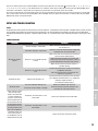
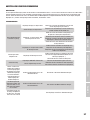
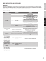
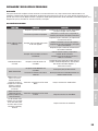
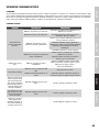
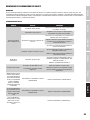
TROUBLESHOOTING
PROBLEM DISPLAY SOLUTION
No sound or volume
too low.
Receiver: Display is switched off.
Make certain that the batteries are not dead and
the receiver is on.
Transmitter: Display is switched off.
Check the connection between power supply and
transmitter. Turn on the transmitter.
Receiver: is on, but the RF indicator
is not lit.
Make certain that the transmitter and receiver are
set to the same radio frequency.
Reduce the distance between transmitter and
receiver and make certain that there is a direct
line of sight between transmitter and receiver.
Make certain that the transmitter antenna is
installed correctly.
Receiver: is on and the RF indicator
is lit.
Increase the volume at the receiver and check the
headphone connection.
Check the input level on the transmitter and
increase it if necessary.
Distortion or noise. Receiver: RF indicator is on.
Increase the distance to possible causes of interfe-
rence (digitally controlled devices, e.g., CD players,
computers, digital consoles…).
Use a different radio frequency.
Distorted sound.
Receiver: LOW BATT LED lights up Replace the batteries with new ones.
Transmitter: Level indicator is too high
Lower the volume at the level controls of the
transmitter or at the source device.
Stereo and Focus mode:
Only the right input
signal of the transmitter
is heard, although the
receiver is in the stereo
mode and both inputs of
the transmitter are used.
Transmitter: The transmitter is in the
mono mode.
Switch the transmitter to the stereo mode.
A mono signal is to be
transmitted, but the sig-
nal is only heard on one
side of the headphones.
Transmitter: The transmitter is in the
stereo mode.
Switch the transmitter to the mono mode.
Two mono signals are
to be heard centred in
the headphones, but are
distributed left and right
Switch the receiver to the Focus mode.

14
DEUTSCHFRANCAIS
ESPAÑOL
ENGLISH
ITALIANO POLSKI
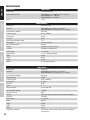
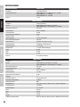
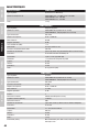
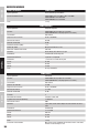
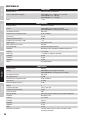
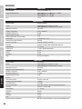
SPECIFICATIONS
Model name: LDMEI1000G2
Product type: In-Ear Monitoring Set
Radio frequency range: LDMEI100G2: 823 - 832 MHz and 863 - 865 MHz
LDMEI100G2B5: 584 – 607 MHz
LDMEI100G2B6: 655 – 679 MHz
Weight: 1,3 kg
LDMEI1000G2BPR
Product type: Belt pack receiver
Channels: LDMEI100G2: 96 (8 groups of 12 channels)
LDMEI100G2B5/B6: 120 (10 groups of 12 channels)
Transmission technology: FM, stereo
Frequency range: 60 Hz - 16000 Hz
Antenna gain: 0.5 dBi
S/N ratio: 80 dB
Total Harmonic Distortion (THD): < 1%
Audio outputs: 3.5 mm stereo jack
Max. audio output level: 100 mW
Controls: Up, Down, Set, Volume, Escape
Indicators LC-Display, Low Battery, RF
Power supply: 2 x 1.5 V AA
Operating time: > 12 hrs., battery-dependent
Width: 65 mm
Height: 90 mm
Depth: 24 mm
Weight: 0,1 kg (without batteries)
LDMEI1000G2T
Product type: Transmitter
Channels: LDMEI100G2: 96 (8 groups of 12 channels)
LDMEI100G2B5/B6: 120 (10 groups of 12 channels)
Transmission technology: FM, stereo
HF output power: 10 mW
Frequency range: 60 Hz - 16000 Hz
Antenna gain: 2.15 dBi
S/N ratio: 85 dB
Inputs: 2
Input connections: 6.3 mm TRS, XLR
Input impedance (kOhm): 14 kOhm
Antenna connector: BNC
Controls: Input Level, Power, Up, Down, Pad, Set, Volume Headphone
Indicators: LC display
Power supply: 12 - 18 V DC
Width: 200 mm
Height: 44 mm
Depth: 96 mm
Weight: 1,2 kg
Accessories (included): User manual, batteries, power supply, antenna, headphones,
rack mount kit

ITALIANO
POLSKI
ESPAÑOL
FRANCAIS
DEUTSCH
ENGLISH
15
MANUFACTURER´S DECLARATIONS
MANUFACTURER‘S WARRANTY & LIMITATIONS OF LIABILITY
You can find our current warranty conditions and limitations of liability at: https://cdn-shop.adamhall.com/media/pdf/MANUFACTU-
RERS-DECLARATIONS_LD_SYSTEMS.pdf To request warranty service for a product, please contact Adam Hall GmbH, Adam-Hall-Str. 1,
61267 Neu Anspach / Email: [email protected] / +49 (0)6081 / 9419-0.
CORRECT DISPOSAL OF THIS PRODUCT
(valid in the European Union and other European countries with a differentiated waste collection system)
This symbol on the product, or on its documents indicates that the device may not be treated as household waste. This is to avoid
environmental damage or personal injury due to uncontrolled waste disposal. Please dispose of this product separately from other waste
and have it recycled to promote sustainable economic activity. Household users should contact either the retailer where they purchased
this product, or their local government office, for details on where and how they can recycle this item in an environmentally friendly manner.
Business users should contact their supplier and check the terms and conditions of the purchase contract. This product should not be mixed
with other commercial waste for disposal.

16
DEUTSCHFRANCAIS
ESPAÑOL
ENGLISH
ITALIANO POLSKI
DEUTSCH
SIE HABEN DIE RICHTIGE WAHL GETROFFEN!
Dieses Gerät wurde unter hohen Qualitätsanforderungen entwickelt und gefertigt, um viele Jahre einen reibungslosen Betrieb zu gewährleisten.
Dafür steht LD Systems mit seinem Namen und der langjährigen Erfahrung als Hersteller hochwertiger Audioprodukte. Bitte lesen Sie diese
Bedienungsanleitung sorgfältig, damit Sie Ihr neues Produkt von LD Systems schnell optimal einsetzen können.
Mehr Informationen zu LD SYSTEMS finden Sie auf unserer Internetseite WWW.LD-SYSTEMS.COM
SICHERHEITSHINWEISE
1. Lesen Sie diese Anleitung bitte sorgfältig durch.
2. Bewahren Sie alle Informationen und Anleitungen an einem sicheren Ort auf.
3. Befolgen Sie die Anweisungen.
4. Beachten Sie alle Warnhinweise. Entfernen Sie keine Sicherheitshinweise oder andere Informationen vom Gerät.
5. Verwenden Sie das Gerät nur in der vorgesehenen Art und Weise.
6. Verwenden Sie ausschließlich stabile und passende Stative bzw. Befestigungen (bei Festinstallationen). Stellen Sie sicher, dass Wandhalterungen
ordnungsgemäß installiert und gesichert sind. Stellen Sie sicher, dass das Gerät sicher installiert ist und nicht herunterfallen kann.
7. Beachten Sie bei der Installation die für Ihr Land geltenden Sicherheitsvorschriften.
8. Installieren und betreiben Sie das Gerät nicht in der Nähe von Heizkörpern, Wärmespeichern, Öfen oder sonstigen Wärmequellen. Sorgen
Sie dafür, dass das Gerät immer so installiert ist, dass es ausreichend gekühlt wird und nicht überhitzen kann.
9. Platzieren Sie keine Zündquellen wie z.B. brennende Kerzen auf dem Gerät.
10. Lüftungsschlitze dürfen nicht blockiert werden.
11. Das Gerät wurde ausschließlich für die Verwendung in Innenräumen entwickelt, betreiben Sie das Gerät nicht in unmittelbarer Nähe von
Wasser (gilt nicht für spezielle Outdoor Geräte - beachten Sie in diesem Fall bitte die im Folgenden vermerkten Sonderhinweise). Bringen Sie
das Gerät nicht mit brennbaren Materialien, Flüssigkeiten oder Gasen in Berührung.
12. Sorgen Sie dafür, dass kein Tropf- oder Spritzwasser in das Gerät eindringen kann. Stellen Sie keine mit Flüssigkeit gefüllten Behältnisse
wie Vasen oder Trinkgefäße auf das Gerät.
13. Sorgen Sie dafür, dass keine Gegenstände in das Gerät fallen können.
14. Betreiben Sie das Gerät nur mit dem vom Hersteller empfohlenen und vorgesehenen Zubehör.
15. Öffnen Sie das Gerät nicht und verändern Sie es nicht.
16. Überprüfen Sie nach dem Anschluss des Geräts alle Kabelwege, um Schäden oder Unfälle, z. B. durch Stolperfallen zu vermeiden.
17. Achten Sie beim Transport darauf, dass das Gerät nicht herunterfallen und dabei möglicherweise Sach- und Personenschäden
verursachen kann.
18. Wenn Ihr Gerät nicht mehr ordnungsgemäß funktioniert, Flüssigkeiten oder Gegenstände in das Geräteinnere gelangt sind, oder das Gerät
anderweitig beschädigt wurde, schalten Sie es sofort aus und trennen es von der Netzsteckdose (sofern es sich um ein aktives Gerät handelt).
Dieses Gerät darf nur von autorisiertem Fachpersonal repariert werden.
19. Verwenden Sie zur Reinigung des Geräts ein trockenes Tuch.
20. Beachten Sie alle in Ihrem Land geltenden Entsorgungsgesetze. Trennen Sie bei der Entsorgung der Verpackung bitte Kunststoff und
Papier bzw. Kartonagen voneinander.
21. Kunststoffbeutel müssen außer Reichweite von Kindern aufbewahrt werden.
BEI GERÄTEN MIT NETZANSCHLUSS:
22. ACHTUNG: Wenn das Netzkabel des Geräts mit einem Schutzkontakt ausgestattet ist, muss es an einer Steckdose mit Schutzleiter
angeschlossen werden. Deaktivieren Sie niemals den Schutzleiter eines Netzkabels.
23. Schalten Sie das Gerät nicht sofort ein, wenn es starken Temperaturschwankungen ausgesetzt war (beispielsweise nach dem Transport).
Feuchtigkeit und Kondensat könnten das Gerät beschädigen. Schalten Sie das Gerät erst ein, wenn es Zimmertemperatur erreicht hat.
24. Bevor Sie das Gerät an die Steckdose anschließen, prüfen Sie zuerst, ob die Spannung und die Frequenz des Stromnetzes mit den auf
dem Gerät angegebenen Werten übereinstimmen. Verfügt das Gerät über einen Spannungswahlschalter, schließen Sie das Gerät nur an die
Steckdose an, wenn die Gerätewerte mit den Werten des Stromnetzes übereinstimmen. Wenn das mitgelieferte Netzkabel bzw. der mitgelieferte
Netzadapter nicht in Ihre Netzsteckdose passt, wenden Sie sich an Ihren Elektriker.
25. Treten Sie nicht auf das Netzkabel. Sorgen Sie dafür, dass spannungsführende Kabel speziell an der Netzbuchse bzw. am Netzadapter
und der Gerätebuchse nicht geknickt werden.
26. Achten Sie bei der Verkabelung des Geräts immer darauf, dass das Netzkabel bzw. der Netzadapter stets frei zugänglich ist. Trennen Sie
das Gerät stets von der Stromzuführung, wenn das Gerät nicht benutzt wird, oder Sie das Gerät reinigen möchten. Ziehen Sie Netzkabel und
Netzadapter immer am Stecker bzw. am Adapter und nicht am Kabel aus der Steckdose. Berühren Sie Netzkabel und Netzadapter niemals
mit nassen Händen.
27. Schalten Sie das Gerät möglichst nicht schnell hintereinander ein und aus, da sonst die Lebensdauer des Geräts beeinträchtigt werden
könnte.
28. WICHTIGER HINWEIS: Ersetzen Sie Sicherungen ausschließlich durch Sicherungen des gleichen Typs und Wertes. Sollte eine Sicherung
wiederholt auslösen, wenden Sie sich bitte an ein autorisiertes Servicezentrum.
29. Um das Gerät vollständig vom Stromnetz zu trennen, entfernen Sie das Netzkabel bzw. den Netzadapter aus der Steckdose.
30. Wenn Ihr Gerät mit einem Volex-Netzanschluss bestückt ist, muss der passende Volex-Gerätestecker entsperrt werden, bevor er entfernt
werden kann. Das bedeutet aber auch, dass das Gerät durch ein Ziehen am Netzkabel verrutschen und herunterfallen kann, wodurch Personen
verletzt werden und/oder andere Schäden auftreten können. Verlegen Sie Ihre Kabel daher immer sorgfältig.
31. Entfernen Sie Netzkabel und Netzadapter aus der Steckdose bei Gefahr eines Blitzschlags oder wenn Sie das Gerät länger nicht verwenden.
32. Das Gerät darf nur im spannungsfreien Zustand (Trennung des Netzsteckers vom Stromnetz) installiert werden.

ITALIANO
POLSKI
ESPAÑOL
FRANCAIS
DEUTSCH
ENGLISH
17
33. Staub und andere Ablagerungen im Inneren des Geräts können es beschädigen. Das Gerät sollte je nach Umgebungsbedingungen
(Staub, Nikotin, Nebel etc.) regelmäßig von qualifiziertem Fachpersonal gewartet bzw. gesäubert werden (keine Garantieleistung), um
Überhitzung und Fehlfunktionen zu vermeiden.
34. Der Abstand zu brennbaren Materialien muss mindestens 0,5 m betragen
35. Netzleitungen zur Spannungsversorgung mehrerer Geräte müssen mindestens 1,5 mm² Aderquerschnitt aufweisen. In der EU müssen
die Leitungen H05VV-F, oder gleichartig, entsprechen. Geeignete Leitungen werden von Adam Hall angeboten. Mit diesen Leitungen können
Sie mehrere Geräte über den Power out Anschluss mit dem Power IN Anschluss eines weiteren Gerätes verbinden. Beachten Sie, dass die
gesamte Stromaufnahme aller angeschlossenen Geräte den vorgegebenen Wert nicht überschreitet (Aufdruck auf dem Gerät). Achten Sie
darauf, Netzleitungen so kurz wie möglich zu halten.
ACHTUNG
Entfernen Sie niemals die Abdeckung, da sonst das Risiko eines elektrischen Schlages besteht. Im
Inneren des Geräts befinden sich keine Teile, die vom Bediener repariert oder gewartet werden können.
Lassen Sie Wartung und Reparaturen ausschließlich von qualifiziertem Servicepersonal durchführen.
Das gleichseitige Dreieck mit Blitzsymbol warnt vor nichtisolierten, gefährlichen Spannungen im Geräteinneren, die einen
elektrischen Schlag verursachen können.
Das gleichseitige Dreieck mit Ausrufungszeichen kennzeichnet wichtige Bedienungs- und Wartungshinweise.
ACHTUNG HOHE LAUTSTÄRKEN BEI AUDIOPRODUKTEN!
Dieses Gerät ist für den professionellen Einsatz vorgesehen. Der kommerzielle Betrieb dieses Geräts unterliegt den jeweils gültigen
nationalen Vorschriften und Richtlinien zur Unfallverhütung. Als Hersteller ist Adam Hall gesetzlich verpflichtet, Sie ausdrücklich auf mögliche
Gesundheitsrisiken hinzuweisen.
Gehörschäden durch hohe Lautstärken und Dauerbelastung: Bei der Verwendung dieses Produkts können hohe Schalldruckpegel (SPL)
erzeugt werden, die bei Künstlern, Mitarbeitern und Zuschauern zu irreparablen Gehörschäden führen können.
Um eine mögliche Schädigung des Hörsinns zu verhindern, vermeiden Sie das Hören bei großem Lautsärkepegel über lange
Zeiträume. Lauter Schalleinfluss kann selbst bei kurzer Dauer zu Hörschäden führen. Bitte halten Sie die Laustärke immer auf
einemangenehmen Level.
EINFÜHRUNG
Das LD Systems MEI1000G2 In-Ear Monitoring-System bietet einen natürlichen Klang, einen großen Dynamikumfang und ein hervorragendes
Übersprechverhalten.
Drei wählbare Monitor-Modi (Mono, Stereo, Focus) sowie einstellbare EQ- und Limiter-Funktionen ermöglichen für jede Anwendung eine natürliche
Klangwiedergabe mit einem Frequenzgang von 60 Hz – 16 kHz, einem hohen Rauschabstand und einem niedrigen Klirrfaktor. Das LD MEI1000G2
ermöglicht den Simultanbetrieb von bis zu 5 Systemen.
Die Ohrhörer bieten einen hohen Tragekomfort, das Multifunktions-Display des Empfängers zeigt alle relevanten Informationen an. Mit hochwertigen
Batterien werden Betriebszeiten von 12 Stunden und mehr erreicht. Ein 19“ Rackmount Kit und eine robuste Transportbox aus ABS-Kunststoff
runden das MEI1000G2 Paket ab.
Der Einsatz des Funkmikrofon-Systems kann (je nach Land) eine Lizenz erfordern. Bitte wenden Sie sich für nähere Informationen an die zuständige
Behörde Ihres Landes.

18
DEUTSCHFRANCAIS
ESPAÑOL
ENGLISH
ITALIANO POLSKI
SYSTEMKOMPONENTEN
POWER
SET
POWER
SET
Sender
Kopfhörer
Empfänger
Netzteil
Batterien (2 x AA)
Antenne

ITALIANO
POLSKI
ESPAÑOL
FRANCAIS
DEUTSCH
ENGLISH
19
ANSCHLÜSSE, BEDIEN- UND ANZEIGEELEMENTE
GERÄTEFRONT SENDER
POWER
SET
2
3
4
5
67
1
8
1
POWER-TASTE
Einschalten: Taste zwei Sekunden gedrückt halten. Ausschalten: Taste zwei Sekunden gedrückt halten.
2
PFEIL NACH OBEN, WERT ERHÖHEN
Siehe „Systemeinstellung”.
3
PFEIL NACH UNTEN, WERT VERRINGERN
Siehe „Systemeinstellung”.
4
PROGRAMMIERTASTE (SET)
Siehe „Systemeinstellung”.
5
LC DISPLAY
Siehe „Systemeinstellung”.
6
EINGANGSPEGEL
Einstellen der Eingangsempfindlichkeit. Um einen optimalen Rauschabstand zu erzielen, bringen Sie das Eingangssignal möglichst in den
Bereich der 0dB Anzeige (Pegelanzeige AF L und AF R im Display), ohne dabei die Verzerrungsgrenze zu überschreiten (PEAK-Segment in
der Pegelanzeige).
7
LAUTSTÄRKEREGLER FÜR DEN KOPFHÖRERANSCHLUSS
Drehen nach links verringert, drehen nach rechts erhöht die Lautstärke. Um Gehörschäden zu vermeiden, vor der Benutzung von Ohr-/Kopf-
hörern die Lautstärke auf ein Minimum stellen, dann die Lautstärke langsam erhöhen. Vorsicht, hohe Lautstärke kann das Gehör dauerhaft
schädigen.
8
PHONES
Kopfhörerausgang 6,3 mm Stereo-Klinke.
GERÄTERÜCKSEITE SENDER
POWER
SET
2 2
3
4
1
1
KLEINSPANNUNGSBUCHSE
Anschluss für Netzteil 12 - 18V DC (im Lieferumfang).

20
DEUTSCHFRANCAIS
ESPAÑOL
ENGLISH
ITALIANO POLSKI
2
BALANCED INPUT LEFT/RIGHT
Symmetrische Eingänge links und rechts (XLR / 6,3 mm Klinke Combo). In der Mono Betriebsart ist lediglich der rechte Eingang (RIGHT) verwendbar.
3
PAD
Schaltbare Pegeldämpfung für hohe Eingangspegel.
Schalter in Position -12 dB: Dämpfung des Eingangssignals um 12 dB.
Schalter in Position 0 dB: Keine Dämpfung des Eingangssignals.
4
ANTENNE
BNC Antennenanschluss 50 Ohm.
BELT PACK SENDER
GÜRTELCLIP
Befestigen Sie den Empfänger mit dem Clip am Gürtel oder einem geeigneten Gurt. Für optimalen Sitz sollte der Clip stets vollständig auf
den Gürtel bzw. Gurt aufgeschoben werden (siehe Abbildung).
ERSETZEN DER BATTERIEN
Um die Batterien zu ersetzen, drücken Sie leicht auf die markierten Stellen an den Seiten des Batteriefachdeckels und klappen diesen nach
vorne. Entnehmen Sie die Batterien, setzen zwei neue AA-Batterien ein (Ausrichtung siehe Abbildung im Batteriefach) und schließen die
Abdeckung. Entnehmen Sie die Batterien bei längerer Nichtbenutzung des Geräts.
Strona się ładuje...
Strona się ładuje...
Strona się ładuje...
Strona się ładuje...
Strona się ładuje...
Strona się ładuje...
Strona się ładuje...
Strona się ładuje...
Strona się ładuje...
Strona się ładuje...
Strona się ładuje...
Strona się ładuje...
Strona się ładuje...
Strona się ładuje...
Strona się ładuje...
Strona się ładuje...
Strona się ładuje...
Strona się ładuje...
Strona się ładuje...
Strona się ładuje...
Strona się ładuje...
Strona się ładuje...
Strona się ładuje...
Strona się ładuje...
Strona się ładuje...
Strona się ładuje...
Strona się ładuje...
Strona się ładuje...
Strona się ładuje...
Strona się ładuje...
Strona się ładuje...
Strona się ładuje...
Strona się ładuje...
Strona się ładuje...
Strona się ładuje...
Strona się ładuje...
Strona się ładuje...
Strona się ładuje...
Strona się ładuje...
Strona się ładuje...
Strona się ładuje...
Strona się ładuje...
Strona się ładuje...
Strona się ładuje...
Strona się ładuje...
Strona się ładuje...
Strona się ładuje...
Strona się ładuje...
Strona się ładuje...
Strona się ładuje...
Strona się ładuje...
Strona się ładuje...
Strona się ładuje...
Strona się ładuje...
Strona się ładuje...
Strona się ładuje...
Strona się ładuje...
Strona się ładuje...
Strona się ładuje...
Strona się ładuje...
Strona się ładuje...
Strona się ładuje...
Strona się ładuje...
Strona się ładuje...
Strona się ładuje...
Strona się ładuje...
Strona się ładuje...
Strona się ładuje...
-
 1
1
-
 2
2
-
 3
3
-
 4
4
-
 5
5
-
 6
6
-
 7
7
-
 8
8
-
 9
9
-
 10
10
-
 11
11
-
 12
12
-
 13
13
-
 14
14
-
 15
15
-
 16
16
-
 17
17
-
 18
18
-
 19
19
-
 20
20
-
 21
21
-
 22
22
-
 23
23
-
 24
24
-
 25
25
-
 26
26
-
 27
27
-
 28
28
-
 29
29
-
 30
30
-
 31
31
-
 32
32
-
 33
33
-
 34
34
-
 35
35
-
 36
36
-
 37
37
-
 38
38
-
 39
39
-
 40
40
-
 41
41
-
 42
42
-
 43
43
-
 44
44
-
 45
45
-
 46
46
-
 47
47
-
 48
48
-
 49
49
-
 50
50
-
 51
51
-
 52
52
-
 53
53
-
 54
54
-
 55
55
-
 56
56
-
 57
57
-
 58
58
-
 59
59
-
 60
60
-
 61
61
-
 62
62
-
 63
63
-
 64
64
-
 65
65
-
 66
66
-
 67
67
-
 68
68
-
 69
69
-
 70
70
-
 71
71
-
 72
72
-
 73
73
-
 74
74
-
 75
75
-
 76
76
-
 77
77
-
 78
78
-
 79
79
-
 80
80
-
 81
81
-
 82
82
-
 83
83
-
 84
84
-
 85
85
-
 86
86
-
 87
87
-
 88
88


LD MEI 1000 G2 BUNDLE Instrukcja obsługi
- Typ
- Instrukcja obsługi
- Niniejsza instrukcja jest również odpowiednia dla
w innych językach
- español: LD MEI 1000 G2 BUNDLE Manual de usuario
- italiano: LD MEI 1000 G2 BUNDLE Manuale utente
- Deutsch: LD MEI 1000 G2 BUNDLE Benutzerhandbuch
- français: LD MEI 1000 G2 BUNDLE Manuel utilisateur
- English: LD MEI 1000 G2 BUNDLE User manual