FLASH F9000382 Instrukcja obsługi

Typ
Instrukcja obsługi
240A DMX CONTROLLER
240ch 2019
User Manual
Instrukcja Obsługi
F9000382
User Manual Instrukcja Obsługi
IMPORTANT!
Do not point strong light output from other fixtures
at the 240A DMX CONTROLLER 240ch 2019, as
intense illumination can damaged the parts.
2. SAFETY INFORMATION
1. INTRODUCTION
THANK YOU FOR PURCHASING 240A DMX CONTROLLER 240ch 2019. FOR SAFETY
REASONS AND TO ENSURE THE TROUBLE-FREE OPERATION, CAREFULLY READ
THE INSTRUCTIONS.
WARNING!
Figure 2.
Shield or shade the head if necessary.
Please keep this User Manual for future
      
another user, be sure that they also receive
this instruction booklet.
Unpack and check carefully there is no
transportation damage before using the

Before operating, ensure that the voltage
and frequency of power supply match the

It’s important to ground the yellow/green
conductor to earth in order to avoid electric
shock.
Disconnect main power before servicing
and maintenance.


only, but always by taking its base.
Maximum ambient temperature is: 40
Don’t operate it where the temperature is
higher than this.
In the event of serious operating problem,
     

carried out by unskilled people can lead to
damage or malfunction. Please contact the
nearest authorized technical assistance
center. Always use the same type spare
parts.
Do not connect the device to any dimmer
pack.
Do not touch any wire during operation
and there might be a hazard of electric
shock.
To prevent or reduce the risk of electrical

rain or moisture.

visibly damaged.
240A DMX CONTROLLER 240ch 2019 Art No F9000382
4. INSTALLATION
3. PRODUCT INFORMATION
Power supply voltage: 90-240V,
Power Input: DC9-12V, 500 mA
Dimension [cm]: H-7,3 W-48,2 D-13,2
Universal DMX-512 Controller
Controls 12 intelligent lights of up to 16
channels
30 banks of 8 scenes, 240 scenes total
6 sets of chases containing 240 scenes
Execute multiple chases simultaneously
Weight [kg]: 3,5kg
Type of packaging: Carton Box
Make sure all necessary cables are
properly connected. Always ensure that

and slipping while operating. Always
ensure that the structure to which you
are attaching the unit is secure and is
able to support a weight of 10 times of
the unit’s weight. Also always use a safety
cable that can hold 12 times of the weight



of the touch of people and has no one pass
by or under it.
4.1 Voltage specification
3.1 Main Features
Input Voltage Total Power Frequency
90-240V 2W 50/60Hz
Re-assignable channels
Wheel assignable Pan/Tilt and 16bit
control
Beat-activation, tap sync, auto run

Polarity selector
Midi compatible
             
             
banks can contain up to 240 steps composed of the saved scenes and in any order. Programs
can be triggered by music, midi,automatically or manually. All chases can be executed at
the same time.

a wheel and LED display indicators for easier navigation of controls and menu functions.

wheel at the same time by means of a programmable wheel.

1
5
6
7
8
16
23 4 9
18 17 26 10 11 12 13 14 15
19
2422
25
23
2120
29 28 27
5. OPERATION
35 36 37 3834
33
32
3130
5.1 Product Overview (FRONT)
5.2 Product Overview (REAR PANEL)
User Manual Instrukcja Obsługi
Item Button or Fader Function
1 Scanner select buttons Fixture selection
2 Scanner indicator LEDS Indicates the xtures currently selected
3 Scene select buttons Universal bump buttons representing scene location for storage and selection
4 Channel faders For adjusting OMX values, Ch 1~8 can be adjusted immediately after pressing the respective
scanner select button, Ch 9~16 after pressing the Page select button
5 Page A Indicator LED Represents Ch 1~8 range selected, Tip! Tap A, B then B again to control both pages
simultaneously.
6 Page B Indicator LED Represents Ch 9~16 range selected
7 Page select button In manual mode, press to toggle between pages of control or to select both pages
simultaneously. Both LEDS on will allow control of both lower and upper range channel.
8 Program button Used to enter programming mode
9Music/Bank Copy button Used to activate Music mode and as the copy command during programming
10 LCD display window Status window displays pertinent operational data
11 Mode Indicator LEDS Provides operating mode status, (manual, music or auto)
12 Bank Up button Function button to traverse Scene/Steps in banks or chases Incremental OMX values while
FINE button is active.
13 Bank Down button Function button to traverse Scene/Steps in banks or chases Decremental OMX values while
FINE button is active.
14 Tap Display button This is a Tap-Sync during playback and during programming changes the DMX value
displayed in the LCD panel to percentages
15 Blackout button Sets the shutter or dimmer value of all xtures to „O” causing all light output to cease
16 Midi/Ree button Activates MIDI external control and also used to conrm the record/save process
17 Assign LED Indicated the controller is in Channel assign mode during the initial setup of the controller
18 Auto/Del button I Used to activate Auto mode and as the delete function key during programming
19 Chaser buttons Chase memor y 1 ~ 6
20 Speed fader This will adjust the hold time of a scene or a step within a chase
21 Fade-Time fader Also considered a cross-fade, sets the interval time between two scenes in a chase
22 Fine button
Activates 16 bit control of the wheel, movement will be in extremely small increments.
Note: While FINE is active Bank UP/DOWN buttons will increase and decrease OMX values
by one for either the wheel or the slider in focus or currently moved.
23 Reverse LED
24 PAN/TILT Wheel (Joystich) Generally used to control the pan and tilt movement of a xture
25 Mode button
26 Override button
27 Fog machine button To activate the fog machine
28 Fog machine ready indicator
29 Fog machine heating indicator
30 Audio input jack Direct audio feed for use in sound-active mode
31 MIDI input port For external triggering of Banks and Chases using a MIDI device
32 DMX polarity switch May be used to correct signal polarity
33 DMX output connector DMX control signal
34 DMX input connector Used to transfer programmed data between 2 controllers
35 Fog machine socket
36 DC Input jack Main power feed
37 USB Lamp socket
38 ON/OFF power switch Turns the controller on and off
240A DMX CONTROLLER 240ch 2019 Art No F9000382
Common Terms
      
intelligent light programming.
Blackout is a state by where all lighting
        
usually on a temporary basis.
DMX-512 is an industry standard
digital communication protocol used in
entertainment lighting equipment. For
more information read Sections OMX
Primer” and „OMX Control Mode” in the
Appendix.
Fixture refers to your lighting instrument
or other device such as a fogger or dimmer
of which you can control.
Programs are a bunch of scenes stacked

either a single scene or multiple scenes in
sequence.
Scenes are static lighting states.
Sliders also known as faders.
Chases can also be called programs. A chase
consists of a bunch of scenes stacked one

Scanner refers to a lighting instrument
with a pan and tilt mirror; however, in
the I LS-CON controller it can be used to
control any DMX-512 compatible device as

MIDI is a standard for representing musical
information in a digital format. A MIDI
input would provide external triggering
of scenes using midi device such as a midi
keyboard.
Stand Alone      
to function independently of an external
controller and usually in sync to music, due
to a built in microphone.
Fade slider is used to adjust the time
between scenes within a chase.
Speed    
scene will hold its state. It is also considered
a wait time.
Shutter is a mechanical device in the

        
intensity of the light output and to strobe.
Patching refers to the process of assigning

SETTING UP THE SYSTEM
1) Plug the AC to DC power supply to the
system back panel and to the mains outlet.
2) Plug in your OMX cable(s) to your
intelligent lighting as described in the
     
Primer on OMX see the OMX Primer”
section in the Appendix of this manual.
FIXTURE ADDRESSING
     
   
       
corresponding apart.
„SCANNER” buttons on the unit, must be
spaced 16 channels.
Fixture or
Scanner #
Default DMX
Starting
Address
Binary Dipswitch
settings switch to
the „On Position
1 1 1
2 17 1, 5
3 33 1, 6
4 49 1, 5, 6
5 65 1, 7
6 81 1, 5, 7
7 97 1, 6, 7
8 113 1, 5, 6, 7
9 129 1, 8
10 145 1, 5, 8
11 161 1, 6, 8
12 177 1, 5, 6, 8
User Manual Instrukcja Obsługi
     
manual for DMX addressing instructions.
       

WHEEL ASSIGNMENT

are alike or share the same control
attributes, the OMX-240A allows the user
to assign the wheel the correct pan and
     
including 16 bit channel assignments. It
also allows the user to re-assign physical

user can combine or unify control of similar
     


Action:
1) press and hold the PROGRAM button
until the led blinks
2) Press and hold FINE & MODE buttons
together
3) times to access the channel assignment


dmx channel.
3) press a SCANNER button that represents

tilt
4) Use the BANKUP/DOWN buttons to
select pan/tilt
Notes:
All wheels can be reassigned to output on a

Press AUTO/DEL&MODE buttons together
to delete the channel assignment mode.

Action:
5) Press the TAP/DISPLAY button to switch
pages
6) Press and hold MODE button, then
press the SCENES buttons to select the
DMXchannel. AII LEDs will blink.
7) Press and hold FINE & MODE buttons to
exit
Notes:
You can re-assign the OMX channel to all
controller fader channels.

Review wheel assignment or reverse
Action: (Reverse Review)
1) Press and hold FINE & MODE buttons
together to access the wheel assignment
mode
2) press a SCANNER button to select a
scanner
3) Press and hold FINE & MODE buttons
together (2) times to exit

Action: (wheel assignment Review)
1) Press and hold FINE & mode buttons
together (2) times to access the channel
reverse mode
2) press a SCANNER button to select a
scanner
3) Press and hold FINE & MODE buttons to
exit
COPY SCANNER
Example: Copying Scanner 1 into Scanner 2
Action:
1) Press and hold SCANNER button # 1.
2) While holding button# 1 press SCANNER
button # 2.

releasing SCANNER button # 2.


Notes:
To save time, you can copy the settings of
one Scanner button to another.
240A DMX CONTROLLER 240ch 2019 Art No F9000382

REVERSE CHANNEL OUTPUT
Action:
1) press and hold the PROGRAM button
until the led blinks
2) Press and hold FINE & MODE buttons
together to access the channel assignment
mode ,then press the SCANNER button
3) Use the Bankup/Down buttons to select
pan/tilt
4) Press the TAP/DISPLAY button to switch
between pages
5) press and hold MODE button, then press
the SCENES buttons to select the DMX
channel. AII LEDs will blink.
6) Press and hold FINE & MODE buttons (2)
times to exit
Notes:
You can permanently reverse the output of
any given channel on the controller.
Press AUTO/DEL&MODE buttons together
to delete the reverse channel.
FADE TIME ASSIGN
You can choose whether the boards fade
time during scene execution is implemented
broadly to all output channels or only to


and colors to change quickly while not

Action:
1) Turn OFF the controller.
2) Hold the MODE and TAP DISPLAY
buttons simultaneously.
3) Turn ON the controller.
4) Press the TAP DISPLAY button to toggle
between the two modes. Either ALL CH (all
channels) or ONLY X/Y (Pan & Tilt only)
5) Press MODE and TAP DISPLAY to save

Notes:
ALL CH: All channels ONLY X/Y: Only Pan
& Tilt
Operation
MANUAL MODE
      
all scanners. You are able to move them
and change attributes by using the channel
faders and wheel.

Action:
1) Press the AUTO DEL button repeatedly
until the MANUAL LED is lit.
2) Select a SCANNER button.

attributes. PAGE/SELECT A/8 button:
Use to switch between fader control of
(A: Ch 1-8 ), (B: Ch 9-16)
TAP DISPLAY button:
Press to toggle the output indicator on the
LCD display between OMX values (0-255)
and percentage (0-100)
Notes:
All changes made while in Manual Mode are
temporary and will not be recorded
REVIEW SCENE OR CHASE
     
already recorded scenes and chases on the
controller. Other wise skip section and go to
programming.
Action: (SCENE Review)
1) Select any one of the 30 banks by pressing
the BANK UP/DOWN buttons.
2) Select a SCENE button (1-8) to review.

attributes.
User Manual Instrukcja Obsługi
Action: (CHASE Review)
1) Press any one of the 6 CHASE buttons.
2) Press the TAP DISPLAY button to view
the step number on the display.
3) Press the BANK UP/DOWN buttons
review all scenes in the chase.
Notes:
Make sure you are still in MANUAL Mode.

Programming

scenes (or steps) that will be called up
      
programs can be created of 8 scenes in each.
ENTERING PROGRAM MODE
1) Press the Program button until the LED
blinks.
CREATE A SCENE
A scene is a static lighting state. Scenes
       
memories on the controller and each bank

can save 240 scenes total.
Action:
1) Press the PROGRAM button until the
LED blinks.
2) Position SPEED and FADE TIME sliders
all the way down.
3) Select the SCANNERS you wish to include
in your scene.
4) Compose a look by moving the sliders
and wheel.
5) Tap MIDI/REG button.
6) Choose a BANK (01-30) to change if
necessary.
7) Select a SCENES button to store.
8) Repeat steps 3 through 7 as necessary.
8 scenes can be recorded in a Program.
9) To exit program mode, hold the
PROGRAM button.
Notes:
Deselect Blackout if LED is lit.

You can access channels 9~16 by pressing

       
control.

       
display will now indicate the Scene number
and Bank number used.
Tip! Press the FINE button, activate
joystick or slider by moving it then use the
Bank Up/Down buttons to change values in
increments of „1” .
Shortcut: Press [PROGRAM]+ [SCANNERS]
Adjust [Faders & Wheel]+[BANK] +[SCENE]
+Press [PROGRAM] to store.
RUNNING A PROGRAM
Action:
1) Use BANK UP/DOWN buttons to change
Program banks if necessary.
2) Press the AUTO DEL button repeatedly
until the AUTO LED turns on.
3) Adjust the PROGRAM speed via the
SPEED fader and the loop rate via the FADE
TIME fader.
4) Alternatively you can tap the TAP
     
two taps sets the time between SCENES (up
to 10 minutes).
Notes:
Deselect Blackout if LED is lit.
Also called a Tap-Sync.
CHECK PROGRAM
Action:
1) Press and hold the PROGRAM button
until the LED blinks.
240A DMX CONTROLLER 240ch 2019 Art No F9000382
2) Use the BANK UP/DOWN buttons to
select the PROGRAM bank to review.
3) Press the SCENES buttons to review each
scene individually.
EDITING A PROGRAM

Action:
1) Press and hold the PROGRAM button
until the LED blinks.
2) Use BANK UP/DOWN buttons to change
Program banks if necessary.
      
SCANNERS button.
      
using the channel faders and wheel.
5) Press the MIDI/REC button to prepare
the save.
6) Select the desired SCENES button to
save.
Notes:
Deselect Blackout if LED is lit.
COPY A PROGRAM
Action:
1) Press and hold the PROGRAM button
until the LED blinks.
2) Use BANK UP/DOWN buttons to select
the PROGRAM bank you will copy.
3) Press the MIDI/REC button to prepare
the copy.
4) Use BANK UP/DOWN buttons to select
the destination PROGRAM bank.
5) Press the MUSIC BANK COPY button to
execute the copy. All LEDs on the controller
will blink.
Notes:
All 8 scenes in a Program bank will be
copied.
Chase Programming
A chase is created by using previously
created scenes. Scenes become steps in a
chase and can be arranged in any order
you choose. It is highly recommended that
      
time; you delete all chases from memory.
See „Delete All Chases” for instructions.
CREATE A CHASE
A Chase can contain 240 scenes as steps.
      
interchangeably.
Action:
1) Press the PROGRAM button until the
LED blinks.
2) Press the CHASE (1-6) button you wish
to program.
3) Change BANK if necessary to locate a
scene.
4) Select the SCENE to insert.
5) Tap the MIDI/REC button to store.
6) Repeat steps 3-5 to add additional
steps in the chase. Up to 240 steps can be
recorded.
7) Press and hold the PROGRAM button to
save the chase.
RUNNING A CHASE
Action:
1) Press a CHASE button then press the
AUTO DEL button.
2) Adjust the Chase speed by tapping the
TAP DISPLAY button twice at a rate of your
choosing.
Notes:

speed (up to 10 minutes)
CHECKING A CHASE
Action:
1) Press and hold the PROGRAM button
until the LED is lit.
2) Select the desired CHASE button.
User Manual Instrukcja Obsługi
3) Press the TAP DISPLAY button to switch
the LCD display to steps.
4) Review each scene/step individually by
using the BANK UP/DOWN buttons.
EDIT CHASE
(COPY BANK INTO CHASE)
Action:
1) Press and hold the PROGRAM button to
enter programming mode.
2) Press the desired CHASE button.
3) Select the BANK to be copied using the
BANK UP/DOWN buttons.
4) Press MUSIC/BANK COPY button to
prepare copy.
5) Press MIDI/REC button to copy the
bank. All LEDs will blink.
EDIT CHASE (COPY SCENE INTO CHASE)
Action:
1) Press and hold the PROGRAM button to
enter programming mode.
2) Press the desired CHASE button.
3) Select the BANK that contains the scene
to be copied using the BANK UP/DOWN
buttons.
4) Press the SCENE button that corresponds
to the scene to be copied.
5) Press MIDI/REG button to copy the
scene. All LEDs will blink.
EDIT CHASE (INSERT SCENE INTO A
CHASE)
Action:
1) Press and hold the PROGRAM button to
enter programming mode.
2) Press the desired CHASE button.
3) Press the TAP DISPLAY to switch the LCD
display to steps view.
4) Use the BANK UP/DOWN buttons to
navigate steps and locate the insert point of
the new scene.

5) Press MIDI/REC button to prepare the
insert.
6) Use the BANK UP/DOWN button to
locate the SCENE.
7) Press the SCENE button that corresponds
to the scene to be inserted.
8) Press MIDI/REC button to insert the
scene. All LEDs will blink.
Notes:
I.e. To insert a scene between Steps 05 and
06 navigate using BANK buttons until the
display reads STEP05.
DELETE A SCENE IN A CHASE
Action:
1) Press and hold the PROGRAM button to
enter programming mode.
2. Press the desired CHASE button that
contains the scene to be deleted.
3) Press the TAP DISPLAY button to switch
the LCD display to steps.
4) Select the scene/step to be deleted using
the BANK UP/DOWN buttons.
5) Press AUTO DEL button to delete the
step/scene. All LEDs will blink.
DELETE A CHASE
Action:
1) Press and hold the PROGRAM button to
enter programming mode.
2. Press the CHASE button (1-6) to be
deleted.
3) Press and hold AUTO DEL button and
the respective CHASE button to delete the
chase. All LEDs will blink.
DELETE ALL CHASE PROGRAMS
CAUTION!     

240A DMX CONTROLLER 240ch 2019 Art No F9000382
individual scenes and program banks will
be preserved.
Action:
1) Turn OFF controller.
2) Press and hold the BANK DOWN button
and the AUTO DEL button while turning
ON the controller.
3) All LEDs will blink.
Scene Programming (Steps)
INSERT A SCENE
Action:
1) Press and hold the PROGRAM button to
enter programming mode.
2) Press the desired CHASE button.
3) Press the TAP DISPLAY to switch the LCD
display to steps view.
4) Use the BANK UP/DOWN buttons to
navigate steps and locate the insert point of
the new scene.

5) Press MIDI/REC button to prepare the
insert.
6) Use the BANK UP/DOWN button to
locate the SCENE.
7) Press the SCENE button that corresponds
to the scene to be inserted.
8) Press MIDI/REC button to insert the
scene. All LEDs will blink.
Notes:
1.e. To insert a scene between Steps 05 and
06 navigate using BANK buttons until the
display reads STEP05.
COPY A SCENE
Action:
1) Press and hold the PROGRAM button to
enter programming mode.
2) Select the BANK that contains the scene
to be copied using the BANK UP/DOWN
buttons.
3) Press the SCENE button that corresponds
to the scene to be copied.
4) Press MIDI/REG button to copy the
scene.
5) Select the destination BANK that contains
the scene memory to record onto using the
BANK UP/DOWN buttons.
6) Press the desired SCENE button to
complete copy. All LEDs will blink.
DELETE A SCENE
Action:
1) Press and hold the PROGRAM button to
enter programming mode.
2) Select the BANK that contains the scene
to be deleted by using the BANK UP/DOWN
buttons.
3) Press and hold the AUTO DEL button.
4) Press the SCENE button that corresponds
to the scene you want to delete. All LEDs
will blink.
Notes:
When deleting a scene the physical location
is not removed, however, all 192 OMX
channels available to the scene will be set to
value 0.
DELETE ALL SCENES
Action:
1) Press and hold the PROGR AM button
and the BANK DOWN button while turning

2) Turn the controller back on.
Notes:
CAUTION!

data will be set to 0.
User Manual Instrukcja Obsługi
Playback
RUNNING IN SOUND-MODE
Action:
1) Press the MUSIC BANK COPY button
until the MUSIC LED turns on.
2) Select the program BANK to run in sound
active mode using the BANK UP/DOWN
buttons.
3) Alternatively you can press a single
CHASE button (1~6) or several CHASE
buttons in sequence and all selected chases
will loop in the order selected.
4) You can adjust the duration time using
the FADE TIME fader.
Notes:
In the Sound mode, programs will be
triggered by the sound using its built-in
microphone.
Multiple chases selected will loop and run
in the order originally selected.
RUNNING IN AUTO-MODE
Action:
1) Press the AUTO DEL button until the
AUTO LED turns on.
2) If a CHASE button is not pressed the
controller will automatically run a BANK
program.
3) Change BANK programs by using BANK
UP/DOWN buttons.
4) Alternatively you can press a single
CHASE button (1~6) or several CHASE
buttons in sequence and all selected chases
will loop in the order selected.
5) You can adjust the time between steps by
moving the SPEED fader and the duration
of the step by moving
the FADE TIME fader.
Notes:
In the Auto mode, programs will be
triggered by controllers fade and speed
time as set on the faders.
Multiple chases selected will loop and run
in the order originally selected.
RUN MULTIPLE CHASES
SIMULTANEOUSLY
Action:
1) Press and hold AUTO DEL button.
2) While holding down AUTO DEL, in
succession press and release each CHASE
you would like to run simultaneously.
Notes:
IMPORTANT!    
scenes running simultaneously that control
    
creating individual color and gobo chases.
BLACKOUT
     

Midi Operation
      
I commands on the MIDI channel which
it is set to full stop. All MIDI control is
performed using Note on commands. All
other MIDI instructions are ignored. To
stop a chase, send the blackout on note.
Action:
1 )Press and hold the MIDI/REC button for
about 3 seconds.
2) Select the MIDI control channel (1~16) via
the BANK UP/DOWN buttons to set.
3) Press and hold the MIDI/REC button for
3 seconds to save settings.
4) To release MIDI control, press any other
button except the BANK buttons during
step 2.
Notes:

receive MIDI note commands.
240A DMX CONTROLLER 240ch 2019 Art No F9000382
MIDI NOTE FUNCTION (TURN ON/OFF)
00 to 07 Scenes 1-8 in BANK 1
08 to 15 Scenes 1-8 in BANK 2
16 to 23 Scenes 1-8 in BANK 3
24 to 31 Scenes 1-8 in BANK 4
32 to 39 Scenes 1-8 in BANK 5
40 to 47 Scenes 1-8 in BANK 6
48 to 55 Scenes 1-8 in BANK 7
56 to 63 Scenes 1-8 in BANK 8
64 to 71 Scenes 1-8 in BANK 9
72 to 79 Scenes 1-8 in BANK 10
80 to 87 Scenes 1-8 in BANK 11
88 to 95 Scenes 1-8 in BANK 12
96 to 103 Scenes 1-8 in BANK 13
104 to 111 Scenes 1-8 in BANK 14
112 to 119 Scenes 1-8 in BANK 15
120 Chase 1
121 Chase 2
122 Chase 3
123 Chase 4
124 Chase 5
125 Chase 6
126 BLACKOUT
3.8 Data Transfer
It is possible to transfer the programs
stored in one DMX-240A controller to
another. Connect from the OMX output
of the programmed controller to the OMX
input of the other.
Action:

SCANNER buttons 2, 3 and SCENE button 1
then turn unit back On.
       
and hold SCANNER buttons 8, 9 and
SCENE button 2 then turn unit back On.
3) Both units are now ready to transmit
and receive. Press SCENE buttons 7 & 8
simult aneously on Source unit to begin
transmission.
Notes:

indicates it is ready to transmit data.
    
this indicates it is ready to receive data
transmission.
User Manual Instrukcja Obsługi
240A DMX CONTROLLER 240ch 2019 Art No F9000382
OSTRZEŻENIE!
WAŻNE!



Rysunek 2. 

    240A DMX CONTROLLER 240ch 2019. Ze
       

1. WPROWADZENIE
2. ZASADY BEZPIECZENSTWA
     
   
   
przez wykwalifikowany personel, aby
  

      


    
    

   

do sieci elektrycznej.
    


    
  

   
stabilnych konstrukcjach.
    
w dobrze wentylowanym pomieszczeniu, w

  
    


3. INFORMACJA O PRODUKCIE
3.1 Główne cechy
4. INSTALACJA
    

     
    
    
     
     
   
   
   
   
    

     

obok ani pod nim.
4.1 Specyfikacja zasilania
Napięcie Zasilania Pobór Mocy Częstotliwość zasilania
90-240V 2W 50/60Hz
Zasilanie: 90-240V,

Wymiary [cm]: H-9 (14,5) W-48,5(60,5)
D-18 (21,5) cm
Waga[kg]: 2,2 (2,8) kg
Pakowanie: Carton Box



         

          
 




Uniwersalny kontroler DMX-512




scen


przypisania

i sterowanie 16-bitowe
Beat-aktywacja, synchronizacja,
automatyczne uruchamianie
Selektor polaryzacji
Kompatybilny z Midi
User Manual Instrukcja Obsługi
1
5
6
7
8
16
23 4 9
18 17 26 10 11 12 13 14 15
19
2422
25
23
2120
29 28 27
35 36 37 3834
33
32
3130
5.1 Product Overview (FRONT)
5.2 Product Overview (REAR PANEL)
240A DMX CONTROLLER 240ch 2019 Art No F9000382
Item Button or Fader Function
1Przyciski wyboru Scanner Wybór urządzenia
2Wskaźniki LED Scanner Wskazuje aktualnie wybrane urządzenia
3Przycisk wyboru Scene Uniwersalne przyciski reprezentujące lokalizację sceny do przechowywania i wyboru
4Faders kanałów Aby dostosować wartości DMX, kanały 1~8 można dostosować natychmiast po naciśnięciu
odpowiedniego przycisku wyboru skanera, kanały 9~16 po naciśnięciu przycisku wyboru
strony
5Page A wskaźnik LED Reprezentuje wybrany zakres kanałów 1~8. Wskazówka! Dotknij A, B, a następnie B
ponownie, aby sterować obiema stronami jednocześnie.
6Page B wskaźnik LED Reprezentuje wybrany zakres kanałów 9~16
7Przycisk wyboru Page W trybie ręcznym naciśnij, aby przełączać między stronami kontroli lub wybrać obie strony
jednocześnie. Obie diody LED włączone pozwolą kontrolować zarówno dolny, jak i górny
kanał.
8Przycisk Program Służy do wejścia w tryb programowania
9Przycisk Music/Bank Copy Służy do włączania trybu muzycznego i jako polecenie kopiowania podczas programowania
10 Wyświetlacz LCD Okno stanu wyświetla odpowiednie dane operacyjne
11 Wskaźnik trybu LEDS Zapewnia stan trybu pracy (ręczny, muzyczny lub automatyczny)
12 Przycisk Bank Up Przycisk funkcyjny do przechodzenia po Scenach / Krokach w bankach lub sekwencjach
Przyrostowe wartości DMX, gdy aktywny jest przycisk FINE.
13 Przycisk Bank Down Przycisk funkcyjny do przechodzenia przez Scene/Steps w bankach lub Chase Decremental
DMX, gdy aktywny jest przycisk FINE.
14 Przycisk Tap Display Jest to funkcja Tap-Sync podczas odtwarzania i podczas programowania zmienia wartość
DMX wyświetlaną na panelu LCD na wartości procentowe.
15 Przycisk Blackout Ustawia wartość migawki lub ściemniacza wszystkich urządzeń na „O”, powodując zanik
światła
16 Przycisk Midi/Rec Aktywuje zewnętrzne sterowanie MIDI, a także służy do potwierdzania procesu nagrywania
/ zapisywania
17 Przypisanie LED Wskazano, że kontroler jest w trybie przypisania kanałów podczas początkowej konguracji
kontrolera
18 Przycisk Auto/Del I Używany do aktywacji trybu Auto i jako klawisz funkcji usuwania podczas programowania
19 Przycisk Chaser Pamięć Chase 1 ~ 6
20 Szybkość Fader Dostosuje czas wstrzymania sceny lub kroku w ramach chase
21 Czas Fader Uważany również za przenikanie, ustawia odstęp czasu między dwiema scenami w pościgu
22 Przycisk Fine
Aktywuje 16-bitowe sterowanie kołem, ruch będzie wykonywany w bardzo małych krokach.
Uwaga: Gdy FINE jest aktywna, przyciski Bank UP / DOWN będą zwiększać i zmniejszać
wartości DMX o jeden dla kółka lub suwaka, na którym znajduje się fokus lub aktualnie
poruszany.
23 Reverse LED
24 PAN/TILT Kółko (Joystick) Zwykle używany do sterowania ruchem pan i tilt urządzenia
25 Przycisk Mode
26 Przycisk Override
27 Przycisk Fog machine Aby aktywować Zadymiarkę
28 Gotowość Fog machine
29 Nagrzanie Fog machine
30 Wejście Audio typu Jack Bezpośredni kanał audio do użytku w trybie aktywacji dźwiękiem
31 Wejście MIDI Do zewnętrznego wyzwalania banków i łańcuchów za pomocą urządzenia MIDI
32 Przełącznik polaryzacji DMX Może służyć do korekcji polaryzacji sygnału
33 Złącze wyjściowe DMX Sygnał sterujący DMX
34 Złącze wejściowe DMX Służy do przesyłania zaprogramowanych danych między 2 kontrolerami
35 Złącze Fog machin
36 Gniazdo wejściowe DC Główne zasilanie
37 Gniazdo lampy USB
38 Włącznik / wyłącznik zasilania Włącza i wyłącza kontroler
User Manual Instrukcja Obsługi
Wyjaśnienie funkcji
   -
wane terminy w programowaniu inteli-

Blackout      -

-
czasowo.
DMX-512   
-

Fixture    
   
    

Programs
-

Scenes
Sliders
Chases    
      
jedna po drugiej.
Scanner-
tleniowego z lustrem obrotowo-uchylnym;

    -
dzeniem kompatybilnym z DMX-512 jako

MIDI to standard przedstawiania infor-
macji muzycznych w formacie cyfrowym.
    -

takiego jak klawiatura midi.
Stand Alone    
    
    -
    -
wanemu mikrofonowi.
Fade
scenami w ramach chase.
Speed      


Shutter    
  
    
   
    
-

KONFIGURACJA SYSTEMU
-
nelu systemu i do gniazda sieciowego.
-
-
wiedniej instrukcji opraw.
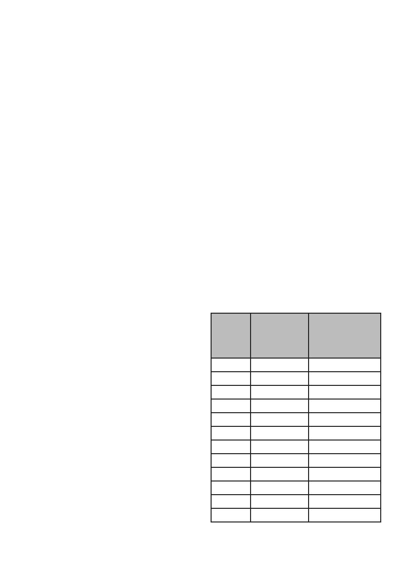
ADRESOWANIE URZĄDZENIA
DMX-240A jest zaprogramowany do ste-
 
-



Urządze-
nie lub
skaner #
Domyślny adres
początkowy
DMX
Ustawienie przełą-
czników binarnych
przełączają się w
pozycję „On Position
1 1 1
2 17 1, 5
3 33 1, 6
4 49 1, 5, 6
5 65 1, 7
6 81 1, 5, 7
7 97 1, 6, 7
8 113 1, 5, 6, 7
9 129 1, 8
10 145 1, 5, 8
11 161 1, 6, 8
12 177 1, 5, 6, 8

     
240A DMX CONTROLLER 240ch 2019 Art No F9000382

  -

PRZYDZIELANIE „KÓŁ
-
      
te same atrybuty sterowania, DMX-240A
-
      
    

-
    
     -

-


Action:
     -

    
-
-
     
     
kanale DMX.
     -
 



Notes:

-



Action:
      


    
     



Notes:



Sprawdź przypisanie kół lub cofnij
Action: (Reverse Review)
-


     
skaner
    


Action: 
     


     
skaner


KOPIOWANIE SCANNER

Action:
     -
NER # 1.
     -
cisk SCANNER 2.
3) Najpierw zwolnij przycisk SCANNER # 1,

-

Notes:
    
User Manual Instrukcja Obsługi
  • Page 1 1
  • Page 2 2
  • Page 3 3
  • Page 4 4
  • Page 5 5
  • Page 6 6
  • Page 7 7
  • Page 8 8
  • Page 9 9
  • Page 10 10
  • Page 11 11
  • Page 12 12
  • Page 13 13
  • Page 14 14
  • Page 15 15
  • Page 16 16
  • Page 17 17
  • Page 18 18
  • Page 19 19
  • Page 20 20
  • Page 21 21
  • Page 22 22
  • Page 23 23
  • Page 24 24
  • Page 25 25
  • Page 26 26
  • Page 27 27
  • Page 28 28
  • Page 29 29
  • Page 30 30
  • Page 31 31
  • Page 32 32

FLASH F9000382 Instrukcja obsługi

Typ
Instrukcja obsługi

w innych językach