
IT
RU
ZH
JA
ES
FR
DE
EN
MIXING CONSOLE
Owner’s Manual
Bedienungsanleitung
Mode d’emploi
Manual de instrucciones
Manuale di istruzioni
EnglishItaliano Español Français Deutsch

1. IMPORTANT NOTICE: DO NOT MODIFY THIS UNIT!
This product, when installed as indicated in the instructions con-
tained in this manual, meets FCC requirements. Modifications
not expressly approved by Yamaha may void your authority,
granted by the FCC, to use the product.
2. IMPORTANT:
When connecting this product to accessories
and/or another product use only high quality shielded cables.
Cable/s supplied with this product MUST be used. Follow all
installation instructions. Failure to follow instructions could void
your FCC authorization to use this product in the USA.
3. NOTE:
This product has been tested and found to comply with
the requirements listed in FCC Regulations, Part 15 for Class
“B” digital devices. Compliance with these requirements pro-
vides a reasonable level of assurance that your use of this prod-
uct in a residential environment will not result in harmful
interference with other electronic devices. This equipment gen-
erates/uses radio frequencies and, if not installed and used
according to the instructions found in the users manual, may
cause interference harmful to the operation of other electronic
devices. Compliance with FCC regulations does not guarantee
* This applies only to products distributed by YAMAHA CORPORATION OF AMERICA. (class B)
that interference will not occur in all installations. If this product
is found to be the source of interference, which can be deter-
mined by turning the unit “OFF” and “ON”, please try to elimi-
nate the problem by using one of the following measures:
Relocate either this product or the device that is being affected
by the interference.
Utilize power outlets that are on different branch (circuit breaker
or fuse) circuits or install AC line filter/s.
In the case of radio or TV interference, relocate/reorient the
antenna. If the antenna lead-in is 300 ohm ribbon lead, change
the lead-in to co-axial type cable.
If these corrective measures do not produce satisfactory results,
please contact the local retailer authorized to distribute this type
of product. If you can not locate the appropriate retailer, please
contact Yamaha Corporation of America, Electronic Service
Division, 6600 Orangethorpe Ave, Buena Park, CA90620
The above statements apply ONLY to those products distributed
by Ya maha Corporation of America or its subsidiaries.
FCC INFORMATION (U.S.A.)
* This applies only to products distributed by
YAMAHA CORPORATION OF AMERICA.
COMPLIANCE INFORMATION STATEMENT
(DECLARATION OF CONFORMITY PROCEDURE)
Responsible Party : Yamaha Corporation of America
Address : 6600 Orangethorpe Ave., Buena Park, Calif. 90620
Telephone : 714-522-9011
Type of Equipment : MIXING CONSOLE
Model Name : IM8-40/IM8-32/IM8-24
This device complies with Part 15 of the FCC Rules.
Operation is subject to the following two conditions:
1) this device may not cause harmful interference, and
2) this device must accept any interference received including interference
that may cause undesired operation.
See user manual instructions if interference to radio reception is sus-
pected.
(FCC DoC)

The above warning is located on the rear of the unit.
Explanation of Graphical Symbols
The lightning flash with arrowhead symbol
within an equilateral triangle is intended to alert
the user to the presence of uninsulated
“dangerous voltage” within the product’s
enclosure that may be of sufficient magnitude to
constitute a risk of electric shock to persons.
The exclamation point within an equilateral
triangle is intended to alert the user to the
presence of important operating and maintenance
(servicing) instructions in the literature
accompanying the product.
IMPORTANT SAFETY INSTRUCTIONS
1 Read these instructions.
2Keep these instructions.
3 Heed all warnings.
4 Follow all instructions.
5 Do not use this apparatus near water.
6 Clean only with dry cloth.
7 Do not block any ventilation openings. Install in
accordance with the manufacturer’s instructions.
8 Do not install near any heat sources such as radiators,
heat registers, stoves, or other apparatus (including
amplifiers) that produce heat.
9 Do not defeat the safety purpose of the polarized or
grounding-type plug. A polarized plug has two blades
with one wider than the other. A grounding type plug has
two blades and a third grounding prong. The wide blade
or the third prong are provided for your safety. If the
provided plug does not fit into your outlet, consult an
electrician for replacement of the obsolete outlet.
10 Protect the power cord from being walked on or pinched
particularly at plugs, convenience receptacles, and the
point where they exit from the apparatus.
11 Only use attachments/accessories specified by the
manufacturer.
12 Use only with the cart, stand,
tripod, bracket, or table specified
by the manufacturer, or sold with
the apparatus. When a cart is
used, use caution when moving
the cart/apparatus combination to
avoid injury from tip-over.
13 Unplug this apparatus during
lightning storms or when unused for long periods of
time.
14 Refer all servicing to qualified service personnel.
Servicing is required when the apparatus has been
damaged in any way, such as power-supply cord or plug
is damaged, liquid has been spilled or objects have
fallen into the apparatus, the apparatus has been
exposed to rain or moisture, does not operate normally,
or has been dropped.
(UL60065_03)
CAUTION: TO REDUCE THE RISK OF
ELECTRIC SHOCK, DO NOT REMOVE
COVER (OR BACK). NO USER-SERVICEABLE
PARTS INSIDE. REFER SERVICING TO
QUALIFIED SERVICE PERSONNEL.
CAUTION
RISK OF ELECTRIC SHOCK
DO NOT OPEN
WARNING
TO REDUCE THE RISK OF FIRE OR ELECTRIC SHOCK, DO NOT EXPOSE THIS APPARATUS TO RAIN OR MOISTURE.

English
Owner’s Manual
4
PRECAUTIONS
PLEASE READ CAREFULLY BEFORE PROCEEDING
* Please keep this manual in a safe place for future reference.
WARNING
Always follow the basic precautions listed below to avoid the possibility of serious injury or even death from electrical
shock, short-circuiting, damages, fire or other hazards. These precautions include, but are not limited to, the following:
• Only use the voltage specified as correct for the device. The required voltage is
printed on the name plate of the device.
• Use only the specified power supply (PW8 or an equivalent recommended by
Yamaha).
• Do not place the power cord near heat sources such as heaters or radiators, and
do not excessively bend or otherwise damage the cord, place heavy objects on
it, or place it in a position where anyone could walk on, trip over, or roll anything
over it.
• Do not open the device or attempt to disassemble the internal parts or modify
them in any way. The device contains no user-serviceable parts. If it should
appear to be malfunctioning, discontinue use immediately and have it inspected
by qualified Yamaha service personnel.
• Do not expose the device to rain, use it near water or in damp or wet conditions,
or place containers on it containing liquids which might spill into any openings.
If any liquid such as water seeps into the device, turn off the power immediately
and unplug the power cord from the AC outlet. Then have the device inspected
by qualified Yamaha service personnel.
• Never insert or remove an electric plug with wet hands.
• If the power cord or plug becomes frayed or damaged, or if there is a sudden
loss of sound during use of the device, or if any unusual smells or smoke
should appear to be caused by it, immediately turn off the power switch,
disconnect the electric plug from the outlet, and have the device inspected by
qualified Yamaha service personnel.
• If this device or power supply should be dropped or damaged, immediately turn
off the power switch, disconnect the electric plug from the outlet, and have the
device inspected by qualified Yamaha service personnel.
CAUTION
Always follow the basic precautions listed below to avoid the possibility of physical injury to you or others, or damage
to the device or other property. These precautions include, but are not limited to, the following:
• Remove the electric plug from the outlet when the device is not to be used for
extended periods of time, or during electrical storms.
• When removing the electric plug from the device or an outlet, always hold the
plug itself and not the cord. Pulling by the cord can damage it.
• When transporting or moving the device, always use two or more people.
Attempting to lift the device by yourself may damage your back, result in other
injury, or cause damage to the device itself.
• Before moving the device, remove all connected cables.
•Avoid setting all equalizer controls and faders to their maximum. Depending on
the condition of the connected devices, doing so may cause feedback and may
damage the speakers.
• Do not expose the device to excessive dust or vibrations, or extreme cold or heat
(such as in direct sunlight, near a heater, or in a car during the day) to prevent
the possibility of panel disfiguration or damage to the internal components.
• Do not place the device in an unstable position where it might accidentally fall
over.
• Do not use the device in the vicinity of a TV, radio, stereo equipment, mobile
phone, or other electric devices. Doing so may result in noise, both in the device
itself and in the TV or radio next to it.
• Before connecting the device to other devices, turn off the power for all devices.
Before turning the power on or off for all devices, set all volume levels to
minimum.
• When turning on the AC power in your audio system, always turn on the power
amplifier LAST, to avoid speaker damage. When turning the power off, the power
amplifier should be turned off FIRST for the same reason.
• Do not insert your fingers or hands in any gaps or openings on the device.
•Avoid inserting or dropping foreign objects (paper, plastic, metal, etc.) into any
gaps or openings on the device. If this happens, turn off the power immediately
and unplug the power cord from the AC outlet. Then have the device inspected
by qualified Yamaha service personnel.
• Do not apply oil, grease, or contact cleaner to the faders. Doing so may cause
problems with electrical contact or fader motion.
• Do not use the headphones or speakers for a long period of time at a high or
uncomfortable volume level, since this can cause permanent hearing loss. If you
experience any hearing loss or ringing in the ears, consult a physician.
• Do not rest your weight on the device or place heavy objects on it, and avoid use
excessive force on the buttons, switches or connectors.
Power supply/Power cord
Do not open
Water warning
If you notice any abnormality
Power supply/Power cord
Location
Connections
Handling caution
(5)-5
1/2

Owner’s Manual
5
English
Always turn the power off when the device is not in use.
The performance of components with moving contacts, such as switches, volume controls, and connectors, deteriorates over time. Consult qualified Yamaha service
personnel about replacing defective components.
SPECIAL NOTICES
• This manual is the exclusive copyright of Yamaha Corporation.
• The software included in the accessory disk and the copyrights thereof are under exclusive ownership by Steinberg Media Technologies GmbH.
• Use of the software and this manual is governed by the license agreement which the purchaser fully agrees to upon breaking the seal of the software packaging. (Please
read carefully the Software Licensing Agreement at the end of this manual before installing the application.)
• Copying of the software or reproduction of this manual in whole or in part by any means is expressly forbidden without the written consent of the manufacturer.
•Yamaha makes no representations or warranties with regard to the use of the software and documentation and cannot be held responsible for the results of the use of this
manual and the software.
• This disk containing the software is not meant for use with an audio/visual system (CD player, DVD player, etc.). Do not attempt to use the disk on equipment other than a
computer.
• Future upgrades of application and system software and any changes in specifications and functions will be announced separately.
The illustrations and LCD screens as shown in this manual are for instructional purposes only, and may appear somewhat different from those on your instrument.
This product incorporates and bundles computer programs and contents in which Yamaha owns copyrights or with respect to which it has license to use others' copyrights.
Such copyrighted materials include, without limitation, all computer software, style files, MIDI files, WAVE data, musical scores and sound recordings. Any unauthorized use
of such programs and contents outside of personal use is not permitted under relevant laws. Any violation of copyright has legal consequences. DON'T MAKE, DISTRIBUTE
OR USE ILLEGAL COPIES.
Copying of the commercially available musical data including but not limited to MIDI data and/or audio data is strictly prohibited except for your personal use.
• Windows is a registered trademark of Microsoft
®
Corporation in the United States and other countries.
• The company names and product names in this manual are the trademarks or registered trademarks of their respective companies.
European models
Purchaser/User Information specified in EN55103-1 and EN55103-2.
Conforms to Environments: E1, E2, E3, E4
Specifications and descriptions in this owner’s manual are for information purposes only.
Yamaha Corp. reserves the right to change or modify products of specifications at any time without prior notice. Since specifications, equipment or options may not be the
same in every locale, please check with your Yamaha dealer.
XLR-type connectors are wired as follows (IEC60268 standard): pin 1: ground, pin 2: hot (+), and pin 3: cold (-).
Insert TRS phone jacks are wired as follows: sleeve: ground, tip: send, and ring: return.
Yamaha cannot be held responsible for damage caused by improper use or modifications to the device, or data that is lost or destroyed.
(5)-5
2/2

English
Introduction
Owner’s Manual
6
Introduction
Thank you for your purchase of the Yamaha IM8 mixing console. Please read through this manual carefully
before beginning use, so that you will be able to take full advantage of your mixer’s superlative features and
enjoy trouble-free operation for years to come. After you’ve read the manual, keep it safe for future reference
when needed.
• Input channels
The console provides 40 monaural input channels (the
IM8-32 has 32 channels, and the IM8-24 has 24 channels)
that can accommodate mic through line-level devices, as
well as four stereo inputs that can accommodate line-level
devices.
• Compressors
A compressor is provided on every monaural channel.
Using just a single knob, you can compress the peaks of
the input signal from a source such as a microphone or
acoustic instrument (e.g., guitar), raising the overall vol-
ume without allowing the sound to distort.
•AUX SEND faders
Faders are provided on the AUX sends, allowing you to
use them not only for the main mix but also to create indi-
vidual mixes for monitoring.
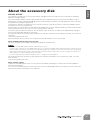
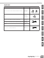
• Owner’s Manual (this book)
•Power supply cable
• Cubase AI 4 DVD-ROM
• USB cable
Introduction .........................................6
Features ................................................................................ 6
Accessories .......................................................................... 6
System Requirements........................................................... 7
Differences between the IM8-40/32/24 mixers ..................... 7
Controls and Functions .......................8
Channel Control Section ....................................................... 8
Master Control Section ....................................................... 12
STEREO AUX RETURN Section.................................... 13
2TR IN/USB Section...................................................... 13
REC OUT/USB Section ................................................. 14
MATRIX OUT Section.................................................... 14
DC POWER INPUT Section........................................... 15
MUTE MASTER Section ................................................ 15
TALKBACK Section ...................................................... 15
AUX SEND Section ....................................................... 16
GROUP OUT Section.................................................... 16
STEREO MASTER Section ............................................ 17
MONITOR Section ........................................................ 18
MONO Section.............................................................. 19
LAMP Connector........................................................... 19
Troubleshooting.................................20
About the accessory disk..................21
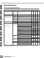
Specifications..................................166
Electrical Specifications.................................................... 166
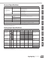
General Specifications...................................................... 167
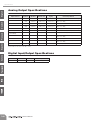
Analog Input Specifications.............................................. 167
Analog Output Specifications ........................................... 168
Digital Input/Output Specifications ................................... 168
Jack List............................................................................ 169
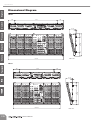
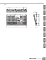
Dimensional Diagram ....................................................... 170
Track Sheet .....................................172
Block Diagram and Level Diagram..174
Features
Accessories
Table of Contents

English
Introduction
Owner’s Manual
7
■
Computer System Requirements
For latest information about the minimum system require-
ments etc., check the web site below.
<http://www.yamahaproaudio.com/>
■
Cubase AI 4 System Requirements
For information about the minimum system requirements and
latest information on Cubase AI, check the web site below.
<http://www.yamahasynth.com/>
The IM8 mixer is available in three models (IM8-40, IM8-32,
IM8-24) which differ as follows.
• Number of monaural input channels
The IM8-40 provides 40 monaural input channels, the IM8-
32 provides 32, and the IM8-24 provides 24. The remain-
ing channels (stereo input channels, 2TR IN, etc.) are the
same for all models.
• Number of LAMP connectors
The IM8-40 provides three LAMP connectors to which you
can connect separately sold gooseneck lamps (e.g.,
Yamaha LA5000), while the IM8-32 and IM8-24 provide
two such connectors.
System Requirements
Differences between the
IM8-40/32/24 mixers

English
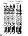
Controls and Functions
Owner’s Manual
8
Controls and Functions
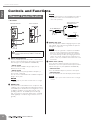
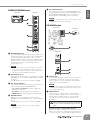
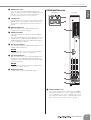
• Rear Panel
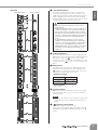
1
INPUT Jack (monaural)
These monaural input jacks are used to connect micro-
phones or musical instruments. Each input channel fea-
tures two types of jacks (INPUT A and INPUT B).
• INPUT A Jack
These are balanced XLR-3-31 type input jacks (1:
Ground; 2: Hot; 3: Cold).
• INPUT B Jack
These are TRS phone-jack type balanced inputs. (T:
Hot; R; Cold; S: Ground)
You can connect either balanced or unbalanced phone
plugs to these jacks.
NOTE
· Only one type of jack can be used at a time on a single
channel.
2
INSERT Jack
These jacks are located between the compressor and
equalizer of the corresponding monaural input channel.
The INSERT jacks are ideal for connecting devices such
as graphic equalizers or noise filters into the corre-
sponding channels. The INSERT jacks are TRS (tip,
ring, sleeve) phone jacks that carry both the send and
return signal (tip = send/out; ring = return/in; sleeve =
ground).
NOTE
· Patching external devices via an INSERT jack requires a
special insert cable such as illustrated below (insert
cable sold separately).
3
DIRECT OUT Jack
These are impedance balanced (page 19) phone-jack
type outputs. They output the signal that has passed
through the compressor.
NOTE
· If necessary, the signal that is output from the DIRECT
OUT jack can be changed to the signal immediately
before the channel fader (pre-fader) or the signal after
the channel fader (post-fader) by changing an internal
jumper. A fee will be charged for this modification. For
details, contact to your Yamaha dealer listed at the end of
this manual.
4
INPUT Jacks (stereo)
These are stereo input jacks that connect line-level
instruments, such as a synthesizer. Each input channel
features two types of jacks (INPUT A and INPUT B).
• INPUT A Jacks
These are unbalanced phone-jack stereo line inputs.
• INPUT B Jacks
These are unbalanced stereo RCA pin-jack line inputs.
NOTE
· Only one type of jack can be used at a time on a single
channel.
Channel Control Section
Tu rn off the Yamaha PW8 power supply before you
connect or disconnect any cables to or from the
console.
1
2
3
4
Monaural channels Stereo channels
To the input jack of the
external processor
To the INSERT jack
Tip: OUT
Tip: IN
To the output jack of the
external processor
Sleeve (Ground)
Ring: IN
Tip: OUT

English
Controls and Functions
Owner’s Manual
9
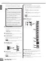
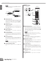
•Top Panel
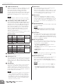
5
+48V Switch/Indicator
This switch toggles phantom power on and off for a
monaural channel. When the switch is turned on, the
+48V indicator will light, and DC +48V phantom power
will be supplied to Pin 2 and 3 of the corresponding
XLR-type INPUT A jacks. Turn this switch on when using
a phantom-powered condenser microphone.
6
26 dB (PAD) Switch
When this switch is turned on, the input signal from the
INPUT jack of the monaural channel is attenuated by 26
dB. Turn the switch off ( ) if you’ve connected a
microphone or other device with a low input level to the
channel. Turn it on ( ) if you’ve connected a line-level
device.
7
GAIN Control
This adjusts the sensitivity of the input signal from the
INPUT jack. Monaural channels have a 26 dB switch
(
6
) that lets you change the range of this control. The
adjustable sensitivity range is as follows.
• Monaural channel
• Stereo channel
-34dB to +10dB
8
(Phase) Switch
Tur ning this switch on will invert the phase of the input
signal. Turn this switch on if you need to mix a phase-
reversed signal.
NOTE
· If you try to mix a phase-reversed signal, the signals will
interfere with each other, resulting in degraded sound
quality.
9
(High Pass Filter) Switch
This switch toggles the HPF on or off.
Tur ning this switch ON will apply a high-pass filter that
attenuates the signal below 80 Hz by a slope of 12 dB/
octave.
5
6
0
9
7
8
A
B
C
D
G
H
F
E
I
J
K
L
Monaural channels Stereo channels
• Be sure to leave this switch off if you do not need
phantom power.
•When turning phantom power on, be sure that only a
condenser microphone is connected to the INPUT A
jack of the monaural channel. Other devices may be
damaged if connected to phantom power. This precau-
tion does not apply to balanced dynamic microphones,
however, as these will not be affected by phantom
power.
•To avoid damage to speakers, be sure to turn off
amplifiers (or powered speakers) before turning this
switch on or off. It’s also a good idea to turn the mixer’s
output controls - STEREO OUT master fader and
GROUP OUT faders - all the way down. If you omit this
precaution, you may damage your hearing or your
equipment.
26 dB switch Range
ON -34dB to +10dB
OFF -60dB to -16dB

English
Controls and Functions
Owner’s Manual
10
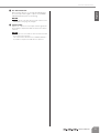
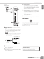
0
COMP Control/Indicator
Adjusts the amount of compression applied to the chan-
nel. As the COMP knob is turned to the right the com-
pression ratio increases while the output gain is
automatically adjusted accordingly. The result is
smoother, more even dynamics because louder signals
are attenuated while the overall level is boosted. The
COMP indicator will light when the compressor oper-
ates.
NOTE
·Avoid setting the compression too high, as the higher
average output level that results may lead to feedback.
A EQ (Equalizer): HIGH, HI-MID, LO-MID, LOW
This is a four-band equalizer, providing adjustments for
four frequency bands (HIGH, HI-MID, LO-MID, LOW).
Setting the gain control to the “▼” position produces a
flat response in the corresponding band. Turning the
gain control to the right boosts the corresponding fre-
quency band, while turning to the left attenuates the
band. The HI-MID and LO-MID bands of monaural
channels provide a frequency control that lets you
adjust the center frequency.
The following table shows the EQ type, frequency, and
maximum cut/boost for each of the bands.
Monaural channel
Stereo channel
B EQ ON Switch
Switches the equalizer on or off.
C AUX Controls (1–8)
These adjust the level of the signals sent from the input
channel to AUX buses 1–8. These knobs should gener-
ally be set close to the “▼” (nominal) position. The sig-
nal adjusted by these controls is determined by the PRE
switch (D).
D PRE Switches
For each two buses, these switches select whether the
signal sent to the AUX buses will be taken after the
equalizer and before the channel fader (pre-fader), or
after the channel fader (post-fader). If this switch is ON,
the pre-fader signal is sent to the AUX bus, and will not
be affected by the channel fader.
NOTE
· If necessary, the pre-fader signal sent to the AUX buses
can be changed to the signal before the equalizer by
changing an internal jumper. A fee will be charged for
this modification. In this case, the signal will be sent to
the AUX buses even if the input channel’s ON switch is
turned off. For details, contact to your Yamaha dealer
listed at the end of this manual.
E PAN Control
This control determines the stereo positioning of the
monaural channel signal on the buses.
Rotate the knob clockwise to pan the signal to the odd
channels of the GROUP buses and the ST L bus, and
counter-clockwise to pan the signal to the even chan-
nels of the GROUP buses and the ST R bus.
F BAL Control
Adjusts the left and right volume balance of stereo
channels. The signal input to the INPUT L jack will be
sent to the odd channels of the GROUP buses or to the
ST L bus, and the signal input to the INPUT R jack will
be sent to the even channels of the GROUP buses or to
the ST R bus.
G ON Switch/Indicator
When this switch is on, that channel will be enabled and
the indicator will light.
NOTE
· Even if the ON switch is off, you can turn on the PFL
switch (K) and monitor the signal before the channel
fader via the MONITOR OUT jacks and the PHONES
jack.
H Input Meter
Three LEDs indicate the input channel signal level after
the equalizer. The “-20” LED will light if the input signal
level reaches -20 dB, and the “0” LED will light at nomi-
nal level. The PEAK LED will light red when the input sig-
nal reaches 3 dB before clipping.
I Bus Assign Switches
These switches determine the bus(es) to which each
channel’s signal is sent. Turning a switch on will output
the signal to the corresponding bus.
• 1-2, 3-4, 5-6, 7-8 switches: Assign the channel’s
signal to the GROUP 1/2–7/8 buses.
• ST switch: Assigns the channel’s signal to the Stereo
L and R buses.
• MONO switch: Assigns the channel’s signal to the
MONO bus.
NOTE
· If you want the signal to be output to the corresponding
bus(es), turn on the channel ON switch (G).
J MUTE Switches (1–4)
These assign the channel’s mute on/off to switches 1–4.
If you turn on the MUTE master switches (1–4)
(page 15) located in the MUTE MASTER section, the
input channels whose corresponding MUTE switch is on
will be muted.
NOTE
·When a channel is muted, the ON indicator (G) will go
dark.
· Even if a channel is muted, you can turn on the PFL
switch (K) and monitor the signal before the channel
fader via the MONITOR OUT jacks and the PHONES
jack.
Band Type Frequency
Maximum
Cut/Boost
HIGH Shelving 10 kHz
±15 dB
HI-MID Peaking 400 Hz – 8 kHz
LO-MID Peaking 80 Hz – 1.6 kHz
LOW Shelving 100 Hz
Band Type Frequency
Maximum
Cut/Boost
HIGH Shelving 10 kHz
±15 dB
HI-MID Peaking 3 kHz
LO-MID Peaking 800 Hz
LOW Shelving 100 Hz

English
Controls and Functions
Owner’s Manual
11
K PFL Switch/Indicator
When the PFL switch is on, the indicator will light and
the channel pre-fader signal is output to the PHONES
and MONITOR OUT jacks for monitoring.
NOTE
·When you turn on the PFL switch, the PFL indicator of the
MONITOR section (page 18) will light.
L Channel Fader
Adjusts the output level of the input channel signal. Use
these faders to adjust the balance between the various
channels.
NOTE
·To minimize noise, the faders of unused channels should
be set to the lowest position.
· The channel faders will affect the ST, MONO, GROUP 1–
8, and AUX 1–8 (when the PRE switch is off) buses.

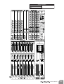
Controls and Functions
Owner’s Manual
12
English
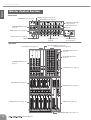
Rear Panel
Top Panel
Master Control Section
DC POWER INPUT
REC OUT/USB Section (page 14)
TALKBACK Section (page 15)
MONITOR Section (page 18)
STEREO MASTER Section
(page 17)
MATRIX OUT Section (page 14)
2TR IN/USB Section (page 13)
MONO Section (page 19) AUX SEND Section
(page 16)
DC POWER INPUT
Section (page 15)
STEREO AUX RETURN
Section (page 13)
GROUP OUT Section
(page 16)
REC OUT/USB Section (page 14)
MATRIX OUT Section (page 14)
DC POWER INPUT Section
(page 15)
MUTE MASTER Section
(page 15)
TALKBACK Section (page 15)
MONITOR Section (page 18)
MONO Section (page 19)
STEREO MASTER Section (page 17)
2TR IN/USB Section (page 13)
STEREO MASTER Section
(page 17)
AUX SEND Section (page 16)
GROUP OUT Section (page 16)

English
Controls and Functions
Owner’s Manual
13
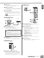
STEREO AUX RETURN Section
1
AUX RETURN Jacks
These are unbalanced phone-jack type line inputs. Sig-
nals input from these jacks can be sent to the GROUP 1/
2–7/8, ST L/R, MONO, and AUX 1–4 buses. To the
MONO and AUX 1–4 buses, a mix of the L/MONO and R
signal is sent. These jacks are typically used to receive
the signal returned from an external effect device
(reverb, delay, etc.).
NOTE
· These jacks can also be used as auxiliary stereo inputs.
· If you connect to the L/MONO jack only, the mixer will
recognize the signal as monaural and will send the identi-
cal signal to both the L/MONO and R jacks.
2 AUX Controls (1–4)
These adjust the level at which the signals from the AUX
RETURN jacks are sent (with L and R mixed) to the AUX
1–4 buses.
The “▼” position of the knob is nominal level (0 dB).
3 Bus Assign Switches
These switches determine the bus(es) to which the sig-
nal is received from the AUX RETURN jacks.
• 1-2, 3-4, 5-6, 7-8 switches: Send the signal to the
GROUP 1/2–7/8 buses.
• ST switch: Sends the signal to the ST L/R bus.
• MONO switch: Sends the signal to the MONO bus.
4 RETURN Control
Adjusts the level of the signal sent from the AUX
RETURN jacks to the GROUP 1/2–7/8, ST L/R, or MONO
buses.
The “▼” position of the knob is nominal level (0 dB).
NOTE
· The signals sent to AUX 1–4 are not affected by the
RETURN control.
5 PFL Switch/Indicator
When the PFL switch is on, the indicator will light and
the signal before the AUX controls and RETURN control
in the STEREO AUX RETURN section is output to the
MONITOR OUT and PHONES jacks for monitoring.
NOTE
·When you turn on the PFL switch, the PFL indicator in the
MONITOR section (page 18) will light.
2TR IN/USB Section
1
2TR IN Jacks
These are RCA pin jacks and a mini-phone jack (stereo)
for inputting a stereo audio source. Use these jacks
when you want to connect a CD player, and output the
signal to the ST L/R or MONO bus.
NOTE
· If signals are simultaneously input from the 2TR IN jacks
(RCA pin jacks, mini-phone jack) and the USB connector,
the signals will be mixed.
2 USB Connector
Connects to the computer via the included cable to
input and output the signals. This connector outputs the
same signal as the REC OUT jacks. The signal input
from this connector is sent to the ST L/R bus or the
MONO bus.
Precautions when using the USB connector
When connecting the computer to the USB connector,
make sure to observe the following points. Failing to do
so risks freezing the computer and corrupting or losing
1
3
4
5
2
Rear Panel Top Panel
When connecting or disconnecting the USB cable
be sure to turn the 2TR IN/USB control all the way
down.
2
3
4
5
1
Top Panel
Rear Panel
Front Panel

English
Controls and Functions
Owner’s Manual
14
the data. If the computer or the instrument freezes,
restart the application software or the computer OS, or
turn the power to the instrument off then on again.
3 Bus Assign Switches
These switches determine the bus(es) to which the sig-
nal received from the 2TR IN jacks and the USB con-
nector is sent.
• ST switch: Sends the signal to the ST L/R bus.
• MONO switch: Sends the mixed L and R signal to
the MONO bus.
4 2TR IN/USB Control
Adjusts the level of the signal received from the 2TR IN
jacks and the USB connector.
5 PFL Switch/Indicator
When the PFL switch is on, the indicator will light and the
signal before the 2TR IN/USB control is output to the MON-
ITOR OUT and PHONES jacks for monitoring.
NOTE
·When you turn on the PFL switch, the PFL indicator of the
MONITOR section (page 18) will light.
REC OUT/USB Section
1 REC OUT Jacks
These RCA pin jacks can be connected to an external
recorder such as an MD recorder in order to record the
signal of the ST L/R bus or MONO bus.
NOTE
· The STEREO OUT master fader and MONO fader has no
affect on the signal via these jacks.
2 Bus Assign Switches
These switches determine the signal sent to the REC
OUT jacks and USB connector. If you’re sending the
signal of the MONO bus, the same signal will be output
to the L and R of the REC OUT jacks and the USB con-
nector.
• ST switch: The signal of the ST L/R bus will be
output from the REC OUT jacks and the USB
connector.
• MONO switch: The signal of the MONO bus will be
output from the REC OUT jacks and the USB
connector.
NOTE
· If both the ST switch and the MONO switch are on, the
mixed signals of the ST L/R bus and MONO bus will be
output.
MATRIX OUT Section
1
MATRIX OUT Jack
This is an impedance balanced (page 19) TRS phone-
jack type output. This jack outputs the signal adjusted
by the controls in the MATRIX OUT section.
2 GROUP Controls (1–8)
These adjust the level of the signals sent from GROUP
OUT 1–8 to the MATRIX OUT jacks.
3 ST Controls (L, R)
These adjust the level of the signals sent from ST OUT L/
R to the MATRIX OUT jacks.
• Use an AB type USB cable of less than about 3
meters.
•To prevent loud pops and noises, turn on the power to
your equipment in the following order; first the audio
sources, then the PW8, and finally the power amplifi-
ers. Reverse this order when turning the power off.
• Before connecting the computer to the USB connector,
exit from any power-saving mode of the computer
(such as suspended, sleep, standby).
• Before turning on the power to the instrument, connect
the computer to the USB connector.
•Execute the following before turning the power to the
instrument on/off or plugging/unplugging the USB
cable to/from the USB connector.
- Quit any open application software on the computer.
-Make sure that data is not being transmitted from
the instrument.
•While the computer is connected to the instrument,
you should wait for six seconds or more between
these operations: (1) when turning the power of the
instrument off then on again, or (2) when alternately
connecting/disconnecting the USB cable.
1
2
Rear Panel Top Panel
1
2
3
4
5
6
Rear Panel Top Panel

English
Controls and Functions
Owner’s Manual
15
4 MONO Control
This control adjusts the level of the signal sent from
MONO OUT to the MATRIX OUT jacks.
5 MATRIX master Control
This control adjusts the overall level of the signal output
to the MATRIX OUT jacks. The “▼” position of the knob
is nominal level (0 dB).
6 AFL Switch/Indicator
When the AFL switch is on, the indicator will light and
the signal after the MATRIX master control is output to
the PHONES and MONITOR OUT jacks for monitoring.
NOTE
· If you want to monitor the signal after the MATRIX master
control, turn off all PFL switches.
DC POWER INPUT Section
1
DC POWER INPUT Connector
Connects the Yamaha Power Supply PW8 to the console
using the included power supply cable.
2 POWER Indicator
This will light when the Yamaha PW8 power supply is
connected to the console and the PW8 is turned on.
MUTE MASTER Section
1
MUTE Master Switches/Indicators (1–4)
These switches toggle input channel muting on and off.
Tur ning a switch (1–4) on will mute the input channels
whose MUTE switch (page 10) of the corresponding
number is turned on. When the signal is muted, the ON
indicator of the input channels will go dark.
TALKBACK Section
1
TALKBACK MIC IN Jack
This is an XLR-3-31 type unbalanced input jack for con-
necting a talkback microphone.
2 Bus Assign Switches
These determine the output destination of the signal
from the TALKBACK MIC jack.
• AUX 1-2, 3-4, 5-6, 7-8 switches: Send the signal to
the AUX 1/2–7/8 buses.
• GROUP 1-8 switch: Sends the signal to the GROUP
1–8 buses.
• STEREO/MONO switch: Sends the signal to the ST
L/R and MONO buses.
• MATRIX 1-2, 3-4 switches: Send the signal to the
MATRIX 1/2 or 3/4 buses.
3 TALKBACK LEVEL Control
Adjusts the level of the signal received from the TALK-
BACK MIC jack.
4 ON Switch/Indicator
When you turn this switch on, the indicator will flash and
the talkback function will be enabled.
•Turn off the Yamaha PW8 power supply before you
connect or disconnect the power supply cable to or
from the console.
•To prevent loud pops and noises, turn on the power to
your equipment in the following order; first the audio
sources, then the PW8, and finally the power amplifi-
ers. Reverse this order when turning the power off.
N
PUT
1
2
Rear Panel Top Panel
1
Top Panel
1
2
3
4
Rear Panel Top Panel

English
Controls and Functions
Owner’s Manual
16
AUX SEND Section
1 AUX INSERT Jack
This is an input/output jack located before the AUX
SEND fader. You can connect a graphic equalizer or
other signal processor. This is a TRS (tip, ring, sleeve)
phone jack that carries both the send and return signal
(tip = send/out; ring = return/in; sleeve = ground).
NOTE
· Patching external devices via an INSERT jack requires a
special insert cable such as illustrated below (insert
cable sold separately).
2 AUX SEND Jacks
These are balanced XLR-3-32 type output jacks (1:
Ground; 2: Hot; 3: Cold). You can use these jacks, for
example, to connect to a monitor system or an external
effect unit.
3 AUX SEND Meter
Three LEDs indicate the signal level after the AUX SEND
fader.
The “-20” LED will light if the output signal level reaches
-20 dB, and the “0” LED will light at nominal level. The
PEAK LED will light red when the output signal reaches
3 dB before clipping.
4 AUX SEND Fader
Controls the level of the signal output to the AUX SEND
jack.
5 AFL Switch/Indicator
When the AFL switch is on, the indicator will light and
the signal after the AUX SEND fader is output to the
MONITOR OUT and PHONES jacks for monitoring.
NOTE
· If you want to monitor the signal after the AUX SEND
fader, turn off all PFL switches.
GROUP OUT Section
1
GROUP INSERT Jack
This is an input/output jack located before the GROUP
OUT fader. You can connect a graphic equalizer or
other signal processor. This is a TRS (tip, ring, sleeve)
phone jack that carries both the send and return signal
(tip = send/out; ring = return/in; sleeve = ground).
NOTE
· Patching external devices via an INSERT jack requires a
special insert cable such as illustrated below (insert
cable sold separately).
1
2
3
4
5
Rear Panel Top Panel
To the input jack of the
external processor
To the INSERT jack
Tip: OUT
Tip: IN
To the output jack of the
external processor
Sleeve (Ground)
Ring: IN
Tip: OUT
1
2
3
4
8
5
6
7
Rear Panel Top Panel
To the input jack of the
external processor
To the INSERT jack
Tip: OUT
Tip: IN
To the output jack of the
external processor
Sleeve (Ground)
Ring: IN
Tip: OUT

English
Controls and Functions
Owner’s Manual
17
2 GROUP OUT Jacks
These are TRS phone type impedance-balanced
(page 19) output jacks that output the GROUP OUT sig-
nals. You can connect these jacks to a multi-track
recorder, external mixer, or other such device.
3 PAN Controls
These adjust the stereo position of the signals sent from
GROUP OUT to the ST L/R bus. Rotate the knob clock-
wise to pan the signal right, and counter-clockwise to
pan left.
4 ON Switch/Indicator
When this switch is on, that GROUP OUT will be
enabled and the indicator will light.
5 GROUP OUT Meter
Three LEDs indicate the signal level after the GROUP
OUT fader.
The “-20” LED will light if the output signal level reaches
-20 dB, and the “0” LED will light at nominal level. The
PEAK LED will light red when the GROUP OUT signal
reaches 3 dB before clipping.
6 Bus Assign Switches
These switches assign the GROUP OUT signal to the ST
L/R bus and the MONO bus.
NOTE
·Turn the ON switch on if you want to send the GROUP
OUT signal to the ST L/R bus or MONO bus.
7 AFL Switch/Indicator
When the AFL switch is on, the indicator will light and
the signal after the GROUP OUT fader but before the
ON switch is output to the MONITOR OUT and PHONES
jacks for monitoring.
NOTE
· If you want to monitor the signal after the GROUP OUT
fader, turn off all PFL switches.
8 GROUP OUT Fader
Controls the level of the GROUP OUT signal.
STEREO MASTER Section
1
STEREO INSERT Jack
This is an input/output jack located before the STEREO
OUT master fader. You can connect a graphic equalizer
or other signal processor. This is a TRS (tip, ring, sleeve)
phone jack that carries both the send and return signal
(tip = send/out; ring = return/in; sleeve = ground).
3
4
7
5
6
1
2
Rear Panel Top Panel

English
Controls and Functions
Owner’s Manual
18
NOTE
· Patching external devices via an INSERT jack requires a
special insert cable such as illustrated below (insert
cable sold separately).
2 STEREO OUT Jacks
These are XLR-3-32 type balanced output jacks that
output the mixed stereo signal. They output the signal
adjusted by the STEREO OUT master faders (7). Con-
nect these jacks to the power amplifiers that drive your
main speakers.
3 STEREO Level Meter
These LEDs indicate the level of the signal sent to the
STEREO OUT jacks.
The “0” segment indicates the nominal output level. The
PEAK segment lights red when the output approaches
the clipping level.
4 ON Switch/Indicator
When this switch is on, ST OUT will be enabled and the
indicator will light.
5 PFL Switch/Indicator
When the PFL switch is on, the indicator will light and
the signal before the STEREO OUT master fader is out-
put to the MONITOR OUT and PHONES jacks for moni-
toring.
6 AFL Switch/Indicator
When the AFL switch is on, the indicator will light and
the signal after the STEREO OUT master faders is out-
put to the PHONES and MONITOR OUT jacks for moni-
toring.
NOTE
· If you want to monitor the signal after the STEREO OUT
master faders, turn off all PFL switches.
7 STEREO OUT Master Faders
These adjust the signal level sent to the STEREO OUT
jacks.
MONITOR Section
1
MONITOR OUT Jacks
These are impedance-balanced (page 19) TRS phone-
type output jacks that you can connect to your monitor
system. These jacks output the signal before or after the
faders for the various buses. The PFL/AFL indicator (4)
and the PFL and AFL indicators in each section indicate
which signal is being output.
NOTE
· If both a PFL switch and AFL switch are on, the PFL
switch will be enabled. If you want to monitor the signals
after the faders, turn off all PFL switches.
2 PHONES Jack
Connects a pair of headphones to this stereo phone-
type output jack. These jacks output the signal before or
after the faders for the various buses.
3 MONITOR Level Meter
Indicates the level of the signal output to the MONITOR
OUT and PHONES jacks.
The “0” segment indicates the nominal output level. The
PEAK segment lights red when the output approaches
the clipping level.
4 PFL/AFL Indicator
Indicates the signal sent to the MONITOR OUT and
PHONES jacks. The PFL indicator will light when the sig-
nals before the faders (control) are being sent; the AFL
indicator will light if the signals after the faders are being
sent.
5 MONITOR Control
Controls the level of the signal output to the MONITOR
OUT jacks.
6 PHONES Control
Controls the level of the signal output to the PHONES
jack.
To the input jack of the
external processor
To the INSERT jack
Tip: OUT
Tip: IN
To the output jack of the
external processor
Sleeve (Ground)
Ring: IN
Tip: OUT
3
2
4
5
6
1
Rear Panel Top Panel
Front Panel

English
Controls and Functions
Owner’s Manual
19
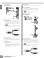
MONO Section
1
MONO INSERT Jack
This is an input/output jack located before the MONO
fader.
You can connect a graphic equalizer or other signal pro-
cessor. This is a TRS (tip, ring, sleeve) phone jack that
carries both the send and return signal (tip = send/out;
ring = return/in; sleeve = ground).
NOTE
· Patching external devices via an INSERT jack requires a
special insert cable such as illustrated below (insert
cable sold separately).
2 MONO OUT Jack
This is an XLR-3-32 type balanced output jack that out-
puts the MONO OUT signal.
3 ON Switch/Indicator
When this switch is on, the MONO OUT will be enabled
and the indicator will light.
4 MONO Level Meter
Three LEDs indicate the signal level after the MONO
fader. The “-20” LED will light if the output signal level
reaches -20 dB, and the “0” LED will light at nominal
level. The PEAK LED will light red when the MONO OUT
signal reaches 3 dB before clipping.
5 AFL Switch/Indicator
When the AFL switch is on, the indicator will light and
the signal after the MONO fader is output to the MONI-
TOR OUT and PHONES jacks for monitoring.
NOTE
· If you want to monitor the signal after the MONO fader,
turn off all PFL switches.
6 MONO Fader
Controls the level of the signal output to the MONO jack.
LAMP Connector
This is an XLR-4-31 type connector that supplies power to a
separately sold gooseneck lamp (e.g., Yamaha LA5000).
The IM8-40 mixer has three of these connectors, and the
IM8-32/24 mixers have two.
1
2
3
6
4
5
Rear Panel Top Panel
To the input jack of the
external processor
To the INSERT jack
Tip: OUT
Tip: IN
To the output jack of the
external processor
Sleeve (Ground)
Ring: IN
Tip: OUT
Impedance balanced:
Since the hot and cold terminals of impedance balanced
output jacks have the same output impedance, these out-
put jacks are less affected by induced noise.

English
Troubleshooting
Owner’s Manual
20
Troubleshooting
Power doesn’t come on.
• Is the dedicated PW8 power supply properly plugged into
an appropriate AC power outlet?
• Is the dedicated PW8 power supply properly connected
using the included power supply cable?
The PW8 itself will not power-on unless it is correctly con-
nected via the included power cable.
• If the above checks do not identify the problem, call
Yamaha for service.
The sound of the bass drum will not move forward in
the mix.
• Could you be mixing a phase-reversed signal?
Try turning on the switch to reverse the phase. If you
are capturing the sound using multiple mics, phase rever-
sal may be causing cancellation.
How can I send the pre-EQ signal to an AUX bus for
monitoring?
• You can send the pre-EQ signal to an AUX bus by
changing an internal jumper setting. Turn the AUX PRE
switch on (pre-fader). In this case, the signal will be sent
to the AUX bus even if the input channel’s ON switch is
off.
How can I monitor the signal of a GROUP bus before I
send it to the ST L/R bus?
• With the GROUP section ON switch turned off, turning the
GROUP section AFL switch on will let you monitor the AFL
signal of the GROUP bus without sending it to the ST L/R
(and MONO) bus.
How can I send a compressed signal to the ST L/R
bus while sending the uncompressed signal to
DIRECT OUT jacks for recording?
• If you connect a compressor (external device) to the
INSERT jacks and apply compression to the signal being
sent to the ST L/R bus, the signal before the compressor
will be sent to the DIRECT OUT jacks. In this case, turn off
the IM8’s COMP control.
How can I send the TALKBACK signal only to the
intercom?
• In the TALKBACK section, turn on only MATRIX 1-2 (or
MATRIX 3-4) to send the output of MATRIX 1-2 (or
MATRIX 3-4) to the intercom.
How can I play background music from a portable
audio player?
•A standard mini-phone type 2TR IN jack is provided on
the front panel, allowing you to connect your portable
audio player via a mini-plug cable.
How can I assign the MC to the MONO bus and also
record it?
• Assign the MC’s input channel to the MONO bus, and use
the REC OUT section bus assign switch to select the
MONO bus.
Strona się ładuje...
Strona się ładuje...
Strona się ładuje...
Strona się ładuje...
Strona się ładuje...
Strona się ładuje...
Strona się ładuje...
Strona się ładuje...
Strona się ładuje...
Strona się ładuje...
Strona się ładuje...
Strona się ładuje...
Strona się ładuje...
Strona się ładuje...
-
 1
1
-
 2
2
-
 3
3
-
 4
4
-
 5
5
-
 6
6
-
 7
7
-
 8
8
-
 9
9
-
 10
10
-
 11
11
-
 12
12
-
 13
13
-
 14
14
-
 15
15
-
 16
16
-
 17
17
-
 18
18
-
 19
19
-
 20
20
-
 21
21
-
 22
22
-
 23
23
-
 24
24
-
 25
25
-
 26
26
-
 27
27
-
 28
28
-
 29
29
-
 30
30
-
 31
31
-
 32
32
-
 33
33
-
 34
34


Yamaha IM8 Instrukcja obsługi
- Kategoria
- Miksery audio
- Typ
- Instrukcja obsługi
w innych językach
- čeština: Yamaha IM8 Uživatelský manuál
- español: Yamaha IM8 Manual de usuario
- italiano: Yamaha IM8 Manuale utente
- Deutsch: Yamaha IM8 Benutzerhandbuch
- svenska: Yamaha IM8 Användarmanual
- português: Yamaha IM8 Manual do usuário
- français: Yamaha IM8 Manuel utilisateur
- Türkçe: Yamaha IM8 Kullanım kılavuzu
- English: Yamaha IM8 User manual
- dansk: Yamaha IM8 Brugermanual
- русский: Yamaha IM8 Руководство пользователя
- suomi: Yamaha IM8 Ohjekirja
- Nederlands: Yamaha IM8 Handleiding
- română: Yamaha IM8 Manual de utilizare
Powiązane artykuły
-
Yamaha PW8 Instrukcja obsługi
-
-
-
Yamaha AG06 Instrukcja obsługi
-
-
-
-
-
-