Feniex Fusion GPL Mini Lightbar Instrukcja obsługi
- Kategoria
- Akcesoria motocyklowe
- Typ
- Instrukcja obsługi

FENIEX // 2018 // INSTRUCTION MANUAL
WEB // www.feniexindustries.com
Feniex Product Copyrights This price List and the mentioned Feniex products include or describe copyrighted Feniex material. Laws in the United States and other countries
preserve for Feniex Industries and its licensors certain exclusive rights for copyrighted material, including the exclusive right to copy, reproduce in any form, distribute and make
derivative works of the copyrighted material. Accordingly, any copyrighted material of Feniex and its licensors contained herein or in the Feniex products described in this Price
List may not be copied, reproduced, distributed, merged or modied, transmitted, transcribed, stored in retrieval system or translated into any language or computer language,
in any form or by any means, without prior written permission of Feniex Industries, Inc.. Feniex and the stylized Feniex logo are registered in the U.S. Patent & Trademark Oce.
FN-8118
INSTRUCTION MANUAL
Is this the latest version?
SCAN HERE
TM

Safety Regulations & Warranty 3
Service after Expiration 3
Copyright 3
Feniex Product Copyright 3
Box Contents, Specications, & Dimensions 4
Box Contents 4
Flash Patterns 4
Specications 4
Dimensions 4
Conguration & Mounting 5
Cigarette Plug Wiring Diagram 5
Cigarette Plug Diagram 5
Hard-Wire Wiring Diagram 5
Power 5
Warning Mode Activation 5
Flash Pattern Selection 5
Takedown & Flood Mode Activation 5
Flashing Takedown Activation 5
Cruise Mode Activation 5
Dim Mode Activation 5
Mounting Instructions 6
Permanent Mount Instructions 5
Magnet Mount Instructions 5
TABLE OF CONTENTS
FENIEX // 2018 // INSTRUCTION MANUAL // v2.0
WEB // www.feniexindustries.com
2
TM

SAFETY REGULATIONS
The following provides all the information necessary to
safely operate the previously listed products of Feniex
Industries, Inc. Please read this manual thoroughly before
installing or operating your new product in order to
prevent any damage or injury. Failure to follow the listed
instructions in this manual may result in damage to your
products or personal injury.
• Proper installation of this product requires good
knowledge of automotive systems, electronics &
procedures.
• Please guarantee all vital components of the vehicle
are not in danger of being damaged by drilling holes
necessary for installation. Check all sides of the
mounting surface before drilling any holes into the
vehicle.
• Do not install this product in any way that interferes
with the deployment of the air bag. Doing so may
damage the eectiveness of the air bag & can lead to
serious personal and vehicle injury. The installer will
assume full responsibility of proper installation of the
new unit.
• Please clean the mounting surface before installation
of the unit when using tape, brackets, magnet, Velcro or
suction cups.
• The product’s ground wire must be connected directly
to the negative (-) battery post for eective use of the
unit. Please follow all wiring guidelines provided to
guarantee long lifespan & productivity. Failing to follow
these instructions may result in damage to the product.
WARRANTY
Feniex Industries, Inc. warrants to the original purchaser
that the product shall be free from defects in material &
workmanship for 5 years from the date of purchase for
all LED products. Feniex Industries warranties speakers,
sirens, ashers, & controllers for 2 years.
If warranty service is needed, please contact customer
support:
Phone: 1.800.615.8350
Web Site: www.Feniex.com/support
Email: techsupport@feniex.com
If the product needs to be returned for repair or
replacement, contact our customer service team (using
any method listed above) to receive a Return Merchandise
Authorization (RMA) number. Operational times are from 9
a.m. to 6 p.m. central time, Monday through Friday.
CONDITIONS
Feniex Industries, Inc. will not be held responsible for any
costs associated with equipment removal and/or
re-installation resulting from a warranty claim. It is the sole
responsibility of the party initiating a warranty claim to pay
shipping charges associated with returning a product to
Feniex Industries for repair or replacement.
SERVICE AFTER EXPIRATION
Feniex Industries will still provide service for all products
after expiration of the warranty. For any issues, call the
customer support line. In some instances it may be
necessary for the product to be shipped, freight prepaid
and insured for loss or damage to Feniex headquarters.
SAFETY REGULATIONS & WARRANTY
Utilizing non-factory screws and mounting brackets may result
in the loss of warranty coverage.
COPYRIGHT
This instruction manual and the Feniex products
described in this instruction manual may include or
describe copyrighted Feniex material. Laws in the United
States and other countries preserve for Feniex Industries
and its licensors certain exclusive rights for copyrighted
material, including the exclusive right to copy, reproduce
in any form, distribute and make derivative works of
the copyrighted material. Accordingly, any copyrighted
material of Feniex and its licensors contained herein or in
the Feniex products described in this instruction manual
may not be copied, reproduced, distributed, merged
or modied in any manner without the express written
permission of Feniex Industries, Inc.
FENIEX PRODUCT COPYRIGHTS
The products described in this document are the property
of Feniex Industries, Inc. It is furnished by express license
agreement only and may be used only in accordance with the
terms of such an agreement. Products and documentation
are copyrighted materials. Making unauthorized copies is
prohibited by law. No part of the product or documentation
may be reproduced, transmitted, transcribed, stored in
retrieval system or translated into any language or computer
language, in any form or by any means, without prior
permission from Feniex Industries, Inc.
Please do not send in product without contacting support rst
for a Return Merchandise Authorization (RMA) number.
FENIEX // 2018 // INSTRUCTION MANUAL // v2.0
WEB // www.feniexindustries.com
3
TM

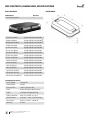
COMPONENTS
QUANTITY
Fusion Mini Lightbar 1
BOX CONTENTS, DIMENSIONS, SPECIFICATIONS
BOX CONTENTS
SYSTEM SPECIFICATIONS
Input Voltage 12 Volts DC
Current Draw 5 Amps
External Fuse
125% of Circuit Load
Color
Amber, Red, Blue, White, Green
Cable
10ft Cable w/Cigarette Plug
SAE Certification
J595, CT13, SAE J1113-11
Flash Patterns
16 (Color 1, Color 2, & Dual Color)
Dimensions
2.33" H x 13.94" L x 8.06" W
Warranty
5 Years
DIMENSIONS
1) Cluster Pattern Single & Dual Color Modes
2) Attack Pattern Single & Dual Color Modes
3) Night Ride Pattern Single & Dual Color Modes
4) Half-Half [Slow Single & Dual Color Modes
5) Half-Half [Fast] Single & Dual Color Modes
6) One-One [Slow] Single & Dual Color Modes
7) One-One [Fast] Single & Dual Color Modes
8) Two-Two [Slow] Single & Dual Color Modes
9) Two -Two [Fast] Single & Dual Color Modes
10) All-On [Slow] Single & Dual Color Modes
11) All-On [Fast] Single & Dual Color Modes
12) In-Out [Slow Single & Dual Color Modes
13) In-Out [Fast] Single & Dual Color Modes
14) Combo: All Slow Single & Dual Color Modes
15) Combo: All Fast Single & Dual Color Modes
16) Combo: Fast & Slow Single & Dual Color Modes
FENIEX // 2018 // INSTRUCTION MANUAL // v2.0
WEB // www.feniexindustries.com
4
TM

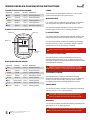
WIRING DIAGRAM & CONFIGURATION INSTRUCTIONS
WIRE COLOR FUNCTION POLARITY CONNECTION
Red
Positive 12v (+) Positive Terminal
Black
Ground 12v (-) Ground Terminal
White
Flood 12v (+) Latching Switch
Yellow
Pattern 12v (+) Momentary Switch
Green
Mode 2 12v (+) Latching Switch
Blue
Cruise Mode 12v (+) Latching Switch
Gray
Dim Mode 12v (+) Latching Switch
Brown
Mode 1 12v (+) Latching Switch
CIGARETTE PLUG WIRING DIAGRAM POWER
To power the unit, extend the red wire to a 12v (+) post.
Extend the black wire to the ground post.
WIRE COLOR FUNCTION POLARITY CONNECTION
Red
Positive 12v (+) Positive Terminal
Black
Ground 12v (-) Ground Terminal
Yellow
Mode 2 12v (+) Latching Switch
Green
Mode 1 12v (+) Latching Switch
Blue
Pattern 12v (+) Momentary Switch
CIGARETTE LIGHTER PLUG DIAGRAM
WARNING MODE
For models with the cigarette lighter adapter, activate the
unit using the 3-way switch to activate modes 1 & 2.
For hard-wire models, activate the unit by extending the
brown & green wires to 12v (+) latching switches.
FLASH PATTERNS
For models with the cigarette lighter adapter, advance the
pattern by pushing the momentary switch for 1 second.
For hard-wire models, advance the pattern by extending
the yellow wire to a 12v (+) momentary switch or tap the
yellow wire to a 12v (+) terminal for 1 second.
TAKEDOWN & FLOOD MODE
Activate the factory congured takedown function by
extending the white wire to a 12v (+) latching switch. For
dual color models, the ood mode will be activated instead
of the takedown function.
Takedown functionality must be specied at time of order.
Modules in takedown positions will only function as takedown
or ashing takedown, no warning patterns will be displayed.
TAKEDOWN FLASHING
Activate the factory congured takedown ashing
function by extending the green wire to a 12v (+) latching
switch. For dual color models, warning mode 2 will be
activated instead of the ashing takedown function.
Mode 2 overrides mode 1 if both wires are activated.
CRUISE MODE
For hard-wire models, activate Cruise Mode by extending
the blue wire to a 12v (+) latching switch.
Cruise Mode is only available on hard-wire models. On single
color models, Cruise will remain active beneath warning
patterns, but will be overriden by dual color warning modes.
DIM MODE
For hard-wire models, activate Dim Mode by extending the
gray wire to a 12v (+) latching switch.
Dim Mode is only available on hard-wire models. This mode will
dim all modes except for Takedown functions & Flood Mode.
Mode 1: On
Flash Pattern
Changer
Mode 2: On
HARD-WIRE WIRING DIAGRAM
Middle: O
FENIEX // 2018 // INSTRUCTION MANUAL // v2.0
WEB // www.feniexindustries.com
5
TM

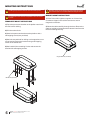
PERMANENT MOUNT INSTRUCTIONS
1) Place the permanent bracket on the platform and mark
the rst hole for drilling.
2) Drill the marked hole.
3) Attach the permanent bracket to the platform with a
self-tapping screw (user provided).
4) Mark the second hole for drilling on the opposite corner
of the bracket. Secure the bracket using a self-tapping
screw on the drilled hole.
5) Mark and drill the remaining 2 holes and secure the
bracket with self-tapping screws.
MOUNTING INSTRUCTIONS
Installing the permanent brackets will involve drilling holes.
The permanent mount bracket is adjustable and can be moved
in or out.
Magnetic mounts are not meant to be used at highway speeds.
It is recommended not to exceed 35MPH with magnet mounts.
MAGNET MOUNT INSTRUCTIONS
1) Place Fusion Mini Lightbar magnets on a at surface,
or between ridges in the rooine to ensure a secure
magnetic connection.
2) Route the cable carefully through the door. Be sure the
cable isn't tightly pinched and that it doesn't interfere with
the door latching securely.
FN-8118-P (optional)
Magnet Mounts (standard)
FENIEX // 2018 // INSTRUCTION MANUAL // v2.0
WEB // www.feniexindustries.com
6
TM
-
 1
1
-
 2
2
-
 3
3
-
 4
4
-
 5
5
-
 6
6


Feniex Fusion GPL Mini Lightbar Instrukcja obsługi
- Kategoria
- Akcesoria motocyklowe
- Typ
- Instrukcja obsługi
w innych językach
Powiązane dokumenty


Inne dokumenty
-
Sea Ray 2007 44DA Parts Manual
-
-
Yamaha PM4000 Instrukcja obsługi
-
-
-
-
Yamaha DGX-530 Instrukcja obsługi
-
-