
ELECTRONICS FOR SPECIALISTS ELECTRONICS FOR SPECIALISTS ELECTRONICS FOR SPECIALISTS ELECTRONICS FOR SPECIALISTS ELECTRONICS FOR SPECIALISTS ELECTRONICS
MPS-1
Bestell-Nr. • Order No. 24.3790
MONACOR INTERNATIONAL GmbH & Co. KG • Zum Falsch 36 • 28307 Bremen • Germany
Copyright
©
by MONACOR INTERNATIONAL. All rights reserved.
A-0285.99.04.03.2017
DIRECT OUT
WWW.IMGSTAGELINE.COM
INPUT
BAL. BAL.
ISO OUT
BAL.
LIFT
GND
2
1
3
1
2
3
2
1
3
431 2
Répartiteur micro
Cette notice s’adresse aux utilisateurs sans
connaissances techniques particulières. Veuil-
lez lire la notice avant le fonctionnement et
conservez-la pour pouvoir, si besoin, vous y
reporter ultérieurement.
1 Possibilités d’utilisation
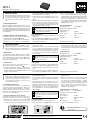
Avec le répartiteur micro MPS-1, un signal micro
peut être réparti sur deux appareils audio (par
exemple table de mixage principale et table de
mixage moniteur). On évite les boucles de ronfle-
ments grâce à la séparation galvanique de l’entrée
(2) et de la sortie ISO OUT (4).
2 Conseils d’utilisation et de sécurité
L’appareil répond à toutes les directives nécessaires
de l’Union européenne et porte donc le symbole .
•
L’appareil n’est conçu que pour une utilisation
en intérieur. Protégez-le des projections d’eau
et éclaboussures, d’une humidité élevée et de la
chaleur (plage de température de fonctionne-
ment autorisée 0 – 40 °C).
•
Pour le nettoyer, utilisez uniquement un chiffon
sec et doux, en aucun cas de produits chimiques
ou d’eau.
•
Nous déclinons toute responsabilité en cas de
dommages matériels ou corporels résultants si
l’appareil est utilisé dans un but autre que celui
pour lequel il a été conçu, s’il n’est pas correc-
tement branché ou s’il n’est pas réparé par une
personne habilitée ; en outre, la garantie devien-
drait caduque.
Lorsque l’appareil est définitivement
retiré du service, vous devez le déposer
dans une usine de recyclage de proximi-
té pour contribuer à son élimination non
polluante.
3 Fonctionnement
1) Reliez le microphone à la prise INPUT (2).
2) Reliez les deux sorties DIRECT OUT (1) et ISO
OUT (4) respectivement à l’entrée micro d’un
appareil audio.
3) Mettez tout d’abord le potentiomètre à glis-
sières (3) vers le bas sur la position GND. Si
une boucle de ronflement venait à se former
dans l’installation audio (ronflement audible
pendant les passages à volume bas), mettez le
potentiomètre sur la position LIFT supé rieure.
Ainsi, la liaison masse entre l’entrée et la prise
ISO OUT est interrompue.
4 Caractéristiques techniques
Bande passante : . . . . . . . 35 – 30 000 Hz
Impédance entrée / sortie : 600 Ω
Température
fonc. autorisée :
. . . . . . . . 0 – 40 °C
Dimensions : . . . . . . . . . . . 100 × 80 × 40 mm
Poids : . . . . . . . . . . . . . . . . 310 g
Branchements : . . . . . . . . . XLR, sym.
Tout droit de modification réservé.
Microphone Splitter
These instructions are intended for users
without any specific technical knowledge.
Please read the instructions carefully prior to
operation and keep them for later reference.
1 Applications
The microphone splitter MPS-1 allows to dis tribute
a microphone signal to two audio units (e. g. main
mixer and monitor mixer). Due to the DC separa-
tion of the input (2) and the output ISO OUT (4),
hum loops are prevented.
2 Safety Notes
This unit corresponds to all relevant directive of
the EU and is therefore marked with
.
•
The unit is suitable for indoor use only. Protect
it against dripping water and splash water, high
air humidity, and heat (admissible ambient tem-
perature range 0 – 40 °C).
•
For cleaning only use a dry, soft cloth; never use
chemicals or water.
•
No guarantee claims for the unit and no liabil ity
for any resulting personal damage or material
damage will be accepted if the unit is used for
other purposes than originally intended, if it is
not correctly connected or if it is not repaired in
an expert way.
If the unit is to be put out of operation
definitively, take it to a local recycling
plant for a disposal which is not harmful
to the environment.
3 Operation
1) Connect the microphone to the jack INPUT (2).
2) Connect the two outputs DIRECT OUT (1) and
ISO OUT (4) to the microphone input of an audio
unit.
3) For the time being, set the sliding switch (3) to
the lower position GND. If there is a hum loop
in the audio system (hum noise audible during
audio passages of low vol ume), set the switch to
the upper position LIFT. Thus, the ground con-
nection between the input and the jack ISO OUT
is interrupted.
4 Specifications
Frequency range: . . . . . . . 35 – 30 000 Hz
Input / Output impedance: 600 Ω
Admissible ambient
temperature:
. . . . . . . . . . 0 – 40 °C
Dimensions: . . . . . . . . . . . 100 × 80 × 40 mm
Weight: . . . . . . . . . . . . . . . 310 g
Connections: . . . . . . . . . . . XLR, bal.
Subject to technical modification.
Mikrofon-Splitter
Diese Anleitung richtet sich an Benutzer ohne
besondere Fachkenntnisse. Bitte lesen Sie die
Anleitung vor dem Betrieb gründlich durch
und heben Sie sie für ein späteres Nachlesen
auf.
1 Einsatzmöglichkeiten
Mit dem Mikrofon-Splitter MPS-1 lässt sich ein
Mikrofonsignal auf zwei Audiogeräte (z. B. Haupt-
mischpult und Monitormischpult) verteilen. Durch
die galvanische Trennung des Eingangs (2) und
des Ausgangs ISO OUT (4) werden Brummschlei-
fen vermieden.
2 Wichtige Hinweise für den Gebrauch
Das Gerät entspricht allen relevanten Richtlinien
der EU und trägt deshalb das -Zeichen.
•
Verwenden Sie das Gerät nur im Innenbereich.
Schützen Sie es vor Tropf- und Spritzwasser,
hoher Luftfeuchtigkeit und Hitze (zulässiger Ein-
satztemperaturbereich 0 – 40 °C).
•
Verwenden Sie für die Reinigung nur ein tro-
ckenes, weiches Tuch, niemals Chemikalien oder
Wasser.
•
Wird das Gerät zweckentfremdet, falsch ange-
schlossen oder nicht fachgerecht repariert, kann
keine Haftung für daraus resultierende Sach-
oder Personenschäden und keine Garantie für
das Gerät übernommen werden.
Soll das Gerät endgültig aus dem Betrieb
genommen werden, übergeben Sie es
zur umweltgerechten Entsorgung einem
örtlichen Recyclingbetrieb.
3 Inbetriebnahme
1) Das Mikrofon an die Buchse INPUT (2) an-
schließen.
2) Die beiden Ausgänge DIRECT OUT (1) und ISO
OUT (4) jeweils mit dem Mikrofoneingang eines
Audiogerätes verbinden.
3) Den Schiebeschalter (3) vorerst nach unten
in die Position GND stellen. Falls sich eine
Brummschleife in der Audioanlage gebildet hat
(Brummton während leiser Audiopassagen zu
hören), den Schalter nach oben in die Position
LIFT schieben. Dadurch wird die Masseverbin-
dung zwischen dem Eingang und der Buchse
ISO OUT unterbrochen.
4 Technische Daten
Frequenzbereich: . . . . . . . 35 – 30 000 Hz
Ein- /Ausgangsimpedanz: . 600 Ω
zulässige Einsatz-
temperatur:
. . . . . . . . . . . 0 – 40 °C
Abmessungen: . . . . . . . . . 100 × 80 × 40 mm
Gewicht: . . . . . . . . . . . . . . 310 g
Anschlüsse: . . . . . . . . . . . . XLR, sym.
Änderungen vorbehalten.
DeutschEnglishFrançais
CARTONS ET EMBALLAGE
PAPIER À TRIER

ELECTRONICS FOR SPECIALISTS ELECTRONICS FOR SPECIALISTS ELECTRONICS FOR SPECIALISTS ELECTRONICS FOR SPECIALISTS ELECTRONICS FOR SPECIALISTS ELECTRONICS
MPS-1
Bestell-Nr. • Order No. 24.3790
MONACOR INTERNATIONAL GmbH & Co. KG • Zum Falsch 36 • 28307 Bremen • Germany
Copyright
©
by MONACOR INTERNATIONAL. All rights reserved.
A-0285.99.04.03.2017
DIRECT OUT
WWW.IMGSTAGELINE.COM
INPUT
BAL. BAL.
ISO OUT
BAL.
LIFT
GND
2
1
3
1
2
3
2
1
3
431 2
Rozdzielacz mikrofonowy
Niniejsza instrukcja przeznaczona jest dla
użytkowników nie posiadających doświad-
czenia oraz wiedzy technicznej. Przed rozpo-
częciem użytkowania prosimy o zapoznanie
się z instrukcją i zachowanie jej do wglądu.
1 Zastosowanie
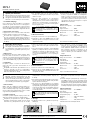
MPS-1 służy do rozdzielenia sygnału mikrofono-
wego do dwóch urządzeń (np. mikser główny,
mikser odsłuchu). Wejście (2) oraz wyjście ISO OUT
(4) jest odizolowane galwanicznie, przez co unika
się problemu przydźwięku sieciowego.
2 Środki ostrożności
Urządzene spełnia wszystkie wymogi norm UE i
dlatego posiadają oznaczenie certyfikatem .
•
Urządzenie jest przeznaczone tylko do użytku
wewnątrz pomieszczeń. Należy chronić przed
dostaniem się jakiejkolwiek cieczy do środka
urządzenia, dużą wilgotnością oraz ciepłem
(temperatura otoczenia powinna wynosić od
0 – 40 °C).
•
Do czyszczenia należy używać tylko suchej, mięk-
kiej ściereczki. Nie wolno używać wody ani żad-
nych środków chemicznych.
•
Nie ponosi się odpowiedzialności za wynikłe
uszkodzenia sprzętu lub obrażenia użytkownika
w przypadku, gdy urządzenia są wykorzystywa-
ne w innych celach niż to się przewiduje lub, jeśli
są nieodpowiednio zain- stalowane, użytkowa-
ne lub naprawiane.
Po całkowitym zakończeniu eksploatacji
urządzenia należy oddać do punktu uty-
lizacji odpadów.
3 Obsługa
1) Podłączyć mikrofon do gniazda wejściowego
INPUT (2).
2) Podłączyć dwa wyjścia DIRECT OUT (1) oraz ISO
OUT (4) do wejść mikrofonowych urządzenia
audio.
3) Ustawić wstępnie przełącznik (3) w dolnej po-
zycji GND. Jeśli w ten sposób powstanie pętla
masy (będzie słyszalny przy niskich głośnościach
przydźwięk sieciowy), przełącznik należy ustawić
w pozycji LIFT. W ten sposób zostanie rozdzielo-
na masa pomiędzy wejściem a wyjściem ISO OUT.
4 Dane techniczne
Pasmo przenoszenia: . . . . 35 – 30 000 Hz
Impedancja
wejściowa / wyjściowa: . . . 600 Ω
Temperatura pracy: . . . . . 0 – 40 °C
Wymiary: . . . . . . . . . . . . . . 100 × 80 × 40 mm
Waga: . . . . . . . . . . . . . . . . 310 g
Podłączenia: . . . . . . . . . . . XLR, zbalansowane
Z zastrzeżeniem do możliwych zmian.
Repartidor de micrófono
Estas instrucciones van dirigidas a usuarios
sin ningún conocimiento técnico específico.
Lea atentamente estas instrucciones antes de
funcionamiento y guárdelas para usos poste-
riores.
1 Aplicaciones
El repartidor de micrófono MPS-1 permite distri-
buir una señal de micrófono a dos aparatos de
audio (p. ej. mezclador principal y mezclador moni-
tor). A causa de la separación DC de la entrada (2)
y de la salida ISO OUT (4), se previenen zumbidos.
2 Seguridad
El aparato cumple con todas las directivas rele-
vantes de la UE y por tanto está marcado con el
símbolo
.
•
El aparato está adecuado para utilizarse sólo en
interiores. Protéjalo de goteos y salpicaduras,
elevada humedad del aire y calor (temperatura
ambiente admisible: 0 – 40 °C).
•
Utilice sólo un paño suave y seco para la limpie-
za; no utilice nunca ni agua ni productos quí-
micos.
•
No podrá reclamarse garantía o responsabilidad
alguna por cualquier daño personal o material
resultante si el aparato se utiliza para otros fines
diferentes a los originalmente concebidos, si no
se conecta adecuadamente, o si no se repara por
expertos.
Si va a poner el aparato definitivamen-
te fuera de servicio, llévelo a la planta
de reciclaje más cercana para que su
eliminación no sea perjudicial para el
medioambiente
3 Funcionamiento
1) Conecte el micrófono la toma INPUT (2).
2) Conecte las dos salidas DIRECT OUT (1) y ISO
OUT (4) cada una a la entrada del micrófono de
un aparato de audio.
3) Por el momento, coloque el interruptor desli-
zante (3) en la posición inferior GND. Si se ha
creado un bucle de zumbido en el sistema de
audio (zumbido audible durante melodías de
bajo volumen), coloque el interruptor en la
posición superior LIFT. Así, la conexión de masa
entre la entrada y la toma ISO OUT se inter-
rumpe.
4 Especificaciones
Rango de frecuencias: . . . 35 – 30 000 Hz
Impedancia
entrada / salida: . . . . . . . . . 600 Ω
Temperatura
ambiente admisible:
. . . . . 0 – 40 °C
Dimensiones: . . . . . . . . . . 100 × 80 × 40 mm
Peso: . . . . . . . . . . . . . . . . . 310 g
Conexiones: . . . . . . . . . . . XLR, sim.
Sujeto a modificaciones técnicas.
Splitter per microfono
Queste istruzioni sono rivolte all‘utente senza
conoscenze tecniche specifiche. Vi preghiamo
di leggerle attentamente prima della messa in
funzione e di conservarle per un uso futuro.
1 Possibilità d’impiego
Con lo splitter per microfono MPS-1 è possibile di-
stribuire un segnale di microfono su due apparec-
chi audio (p. es. mixer principale e mixer monitor).
Grazie alla separazione galvanica dell’ingresso (2) e
dell’uscita ISO OUT (4) si evitano degli anelli di terra.
2 Avvertenze di sicurezza
Il apparecchio è sono conforme a tutte le direttive
rilevanti dell’UE e pertanto porta la sigla .
•
Far funzionare l’apparecchio solo all’interno
di locali. Proteggerlo dall’acqua gocciolante e
dagli spruzzi d’acqua, da alta umidità dell’aria e
dal calore (temperatura d’impiego ammessa fra
0 e 40 °C).
•
Per la pulizia usare solo un panno morbido,
asciutto; non impiegare in nessun caso prodotti
chimici o acqua.
•
Nel caso d’uso improprio, di collegamenti
sbagliati o di riparazione non a regola d’arte
dell’apparecchio, non si assume nessuna re spon-
sabilità per eventuali danni consequenziali a
persone o a cose e non si assume nessuna garan-
zia per l’apparecchio.
Se si desidera eliminare l’apparecchio
definitivamente, consegnarlo per lo
smaltimento ad un‘istituzione locale per
il riciclaggio.
3 Messa in funzione
1) Collegare il microfono con la presa INPUT (2).
2) Collegare le due uscite DIRECT OUT (1) e ISO
OUT (4) ognuna con l’ingresso microfono di un
apparecchio audio.
3) Per il momento, spostare l’interruttore (3) verso
il basso, in posizione GND. Se nell’impianto
audio si è creato un anello di terra (ronzio du-
rante i brani a basso volume), spostare l’interrut-
tore in alto in posizione LIFT. In questo modo, il
collegamento di massa fra l’ingresso e la presa
ISO OUT viene interrotto.
4 Dati tecnici
Gamma di frequenze: . . . 35 – 30 000 Hz
Impedenza
ingresso / uscita: . . . . . . . . . 600 Ω
Temperatura d’esercizio: . 0 – 40 °C
Dimensioni . . . . . . . . . . . . 100 × 80 × 40 mm
Peso: . . . . . . . . . . . . . . . . . 310 g
Collegamenti: . . . . . . . . . . XLR, simm.
Con riserva di modifiche tecniche.
ItalianoEspañolPolski
-
 1
1
-
 2
2


w innych językach
- español: IMG STAGELINE MPS-1 Manual de usuario
- italiano: IMG STAGELINE MPS-1 Manuale utente
- Deutsch: IMG STAGELINE MPS-1 Benutzerhandbuch
- français: IMG STAGELINE MPS-1 Manuel utilisateur
Powiązane artykuły
-
IMG STAGELINE 20.2160 Instrukcja obsługi
-
-
IMG STAGELINE MMX-11USB Instrukcja obsługi
-
IMG STAGELINE TXS-646 Instrukcja obsługi
-
-
-
IMG STAGELINE DM-1100 Instrukcja obsługi
-
-
IMG STAGELINE TXS-636SET Instrukcja obsługi
-