
PM5DV2/DSP5D Editor Owner’s Manual
1
❏
Special Notices
•The software and this owner’s manual are the exclusive copyrights of Yamaha Corporation.
•Copying of the software or reproduction of this manual in whole or in part by any means is expressly forbidden without the
written consent of the manufacturer.
•Copying of the commercially available music sequence data and/or digital audio files is strictly prohibited except for your per-
sonal use.
•Yamaha makes no representations or warranties with regard to the use of the software and documentation and cannot be held
responsible for the results of the use of this manual and the software.
•The screen displays as illustrated in this owner’s manual are for instructional purposes, and may appear somewhat different
from the screens which appear on your computer.
•Future upgrades of application and system software and any changes in specifications and functions will be announced separately.
•Windows is a registered trademark of Microsoft Corporation in the U.S. and other countries.
•Apple, Mac and Macintosh are trademarks of Apple Inc., registered in the U.S. and other countries.
•The company names and product names in this Owner’s Manual are the trademarks or registered trademarks of their respec-
tive companies.
Yamaha Pro Audio Global Site
http://www.yamahaproaudio.com/
Contents
Getting Started .................................................. 2
INPUT CH window ............................................. 8
ST IN window................................................... 11
FX RTN window................................................ 13
MIX window..................................................... 15
MATRIX window .............................................. 17
STEREO window ............................................... 19
DCA window .................................................... 21
Selected Channel window ............................... 22
If an input channel is selected ....................... 22
If a MIX channel is selected ........................... 31
If a MATRIX channel is selected..................... 36
If a STEREO A/B channel is selected............... 37
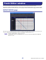
Patch Editor window........................................ 40
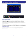
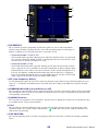
Surround Editor window.................................. 45
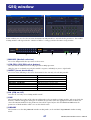
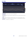
GEQ window .................................................... 47
Effect Editor window........................................ 50
DCA/Mute Group window............................... 54
Scene window .................................................. 57
Library window ................................................ 66
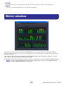
Meter window.................................................. 68
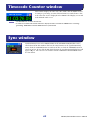
Timecode Counter window.............................. 69
Sync window .................................................... 69
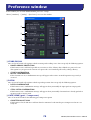
Preference window .......................................... 70
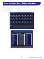
User Defined Keys Setup window.................... 72
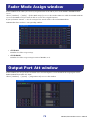
Fader Mode Assign window............................. 73
Output Port Att window .................................. 73
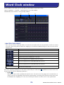
Word Clock window......................................... 74
Oscillator window ............................................ 77
Cue/Solo window............................................. 79
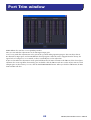
Port Trim window ............................................ 82
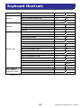
Keyboard Shortcuts.......................................... 83
Index................................................................. 84
*Specifications and descriptions in this owner ’s manual are
for information purposes only. Yamaha Corp. reserves the
right to change or modify products or specifications at any
time without prior notice. Since specifications, equipment
or options may not be the same in every locale, please
check with your Yamaha dealer.
PM5DV2/DSP5D Editor
PM5DV2/DSP5D Editor
PM5DV2/DSP5D Editor
Owner’s Manual
Owner’s Manual
Owner’s Manual
Term Definition
Studio Manager refers to Studio Manager V2
PM5D Editor
refers to PM5DV2 Editor
This editor works with PM5DV2. Make sure that the console’s firmware has been updated to V2.
Description of menus and buttons
In the event that menu and button names on a Windows system are different from those on a Mac, this manual uses the
Windows menu and button names followed by the Mac menu and button names in parentheses.

PM5DV2/DSP5D Editor Owner’s Manual
2
What is PM5D/DSP5D Editor?
PM5D Editor and DSP5D Editor allow you to remotely control the parameters of the PM5D or DSP5D, and save the
parameters on your computer.
PM5D/DSP5 Editor are used by starting them up from within Studio Manager. To use PM5D/DSP5D Editor, you
must perform the following steps.
“Start up Studio Manager and make settings”
→
“Start up PM5D Editor or DSP5D Editor and make settings”
→
“Synchronize with the PM5D/DSP5D itself (
➥
p.5)”
For details on operations in Studio Manager, refer to the Studio Manager operating manual.
Settings in PM5D/DSP5D Editor
You will need to set the following items individually for each editor that is open.
• Before you make the following settings, you must select the MIDI ports in the Setup window of Studio
Manager.
•To start up PM5D Editor or DSP5D Editor in the Setup window of Studio Manager, double-click the cor-
responding icon in the Studio Manager window.
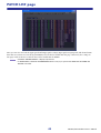
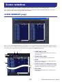
❏
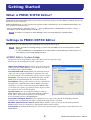
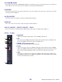
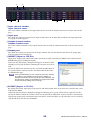
PM5D Editor: System Setup
To open the System Setup window, choose the [File] menu item [System Setup].
You must specify the Input port and the Output port.
Input port/Output port:
From the ports you have previ-
ously specified in Studio Manager, select the ports you will use
for communication with the PM5D.
Console Device ID:
PM5D Editor can control the desired
single unit chosen from a maximum of eight units that each
have their own ID. Select the ID of the unit you want to control.
Fast Sync:
This shortens the synchronization time with the
PM5D itself. If synchronization fails, clear this check box.
Level Meter:
This specifies whether level meter data will be
included in the communication with the PM5D itself. If this
check box is selected, level meter data from the PM5D will be
received, but the response speed may be slower. If you feel that
the response is slow, clear this check box.
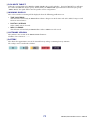
System Color:
You can change the workspace color of
PM5D Editor. Choose one of eight colors from the pulldown
menu. This is convenient when you need to distinguish
between multiple instances of PM5D Editor.
Synchronize Plug-in Boards:
If these option boxes are selected, the data of the Y96K plug-in board
installed in the corresponding slot will be synchronized along with the scene data.
Window Control from Console:
PM5D Editor windows can be opened or closed remotely from the
PM5D itself by using user-defined keys. This option enables remote control.
Set Default:
By clicking this button, you can store the current System Setup settings as the default values for
PM5D Editor.
Getting Started
NOTE
NOTE

PM5DV2/DSP5D Editor Owner’s Manual
3
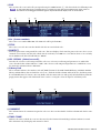
❏
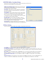
DSP5D Editor: System Setup
To open the System Setup window, choose [System Setup] from the [File] menu.
You must specify the Input port and Output port.
Input port/Output port:
From the ports you have previ-
ously specified in Studio Manager, select the ports you will use
for communication with the DSP5D.
Fast Sync:
This shortens the time required for synchroniza-
tion with the DSP5D. If synchronization fails, you should dis-
able (clear) this item.
Level Meter:
This specifies whether level meter data will be
included in the communication with the DSP5D. If this check
box is selected, level meter data from the DSP5D will be
received, but the response speed may be slower. If you feel that
the response is slow, clear this check box.
System Color:
You can change the workspace color of
DSP5D Editor. Choose one of eight colors from the pulldown
menu. This is convenient when you need to distinguish
between multiple instances of DSP5D Editor.
Set Default:
By clicking this button, you can store the cur-
rent System Setup settings as the default values for DSP5D Editor.
❏
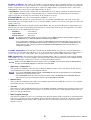
Mixer Setup
To open the Mixer Setup window, choose [Mixer Setup] from the [File] menu.
Pair Mode:
Select whether faders will be paired Horizontally or Vertically.
Pan Nominal Position:
Select whether the signal will be at nominal level when panned to the center (Cen-
ter) or when panned all the way to left or right (L<-->R). You can make separate settings for monaural channels
and paired channels.
Bus Setup:
Select the MIX bus mode (VARI/FIXED) for every two adjacent odd-numbered/even-numbered
MIX buses. MIX buses assigned as surround buses are indicated as “SURROUND” and cannot be changed.
Surround Bus Allocation:
Select the MIX buses (MIX 1–8 or MIX 9–16) that will be used as surround
buses.
Stereo B Setup:
Specify whether the same signal as the STEREO A bus will be sent to the STEREO B bus (Ste-
reo Bus), or whether the STEREO B bus will function as the CENTER bus for LCR mode (Center Bus).

PM5DV2/DSP5D Editor Owner’s Manual
4
Number of Effects:
This changes the number of assigned internal effects and GEQ modules. Decreasing the
number of internal effects by one will increase the number of available GEQ modules by one. You can change the
number assigned between eight internal effects (and twelve GEQ modules) to no internal effects (and twenty
GEQ modules). You can use up to eight GEQ modules as effects.
+48V Master:
This function is found only in DSP5D Editor. It is the master switch for the phantom power
(+48V) supplied to INPUT jacks 1–48 and ST IN jacks 1–4. If this switch is off, phantom power will not be
applied, regardless of whether the +48V shown in the display is on or off.
Surround Mode:
Select the surround mode (STEREO, 3-1, 5.1, 6.1).
External HA:
This specifies the connection ports for external HA (AD8HR) units connected via the slots.
External HA units are assigned an ID of 1–8 (1–4 on the DSP5D), and here you can select the ports to which each
will be connected.
IP Address:
This function is found only in DSP5D Editor. You can specify the IP Address, Subnet Mask, and
Default Gateway values. If the DSP5D and computer are connected in a one-to-one correspondence, we recom-
mend that you use the following default values.
•
IP Address
................... 192.168.0.129
•
Subnet Mask
............... 255.255.255.0
•
Default Gateway
......... 192.168.0.1
•For details on network settings for your computer, refer to DME-N Network Driver installation guide for
DSP5D(Windows) or Network-MIDI Driver installation guide(Mac).
• If you changed the IP Address, you must close DSP5D Editor and Studio Manager, and re-specify the
IP Address values for the DME-N Network Driver communication port or the Network-MIDI Driver com-
munication port. The connection between the DSP5D and DSP5D Editor will be broken when you
change the IP Address
Cascade Connection:
This function is found only in DSP5D Editor. It specifies the Cascade Machine ID
when using a cascade connection. If this is set to 1, you will be able to make DME Connection settings. If this is
set to 2 or 3, the Cascade setting will be Slave, and you won’t be able to make DME Connection settings.
DME Connection:
This function is found only in DSP5D Editor. This is a setting for connecting the DSP5D
with a DME series unit (except the DME32). For details on the connection method, refer to the Global function
MIDI Remote Function section in the reference section of the DSP5D manual.
Even if you enable DME Connection, remote control of the DME cannot be performed from DSP5D Editor.
Use the separate DME Designer to remotely control the DME.
• Input Port / Output Port
This specifies the DSP5D’s connector/slot to which the DME is connected. You can choose SLOT1, SLOT2,
CASCADE IN/OUT D-SUB, or CASCADE OUT RJ-45.
• If you select CASCADE IN/OUT D-SUB or CASCADE OUT RJ-45, the Slot display area of Patch Editor
will show the selected connector/slot.
• Since CASCADE IN RJ-45 cannot be used, you must connect the DSP5D via its CASCADE OUT RJ-
45 connector if you use an Ethernet cable to connect the DME and DSP5D.
• Monitor Port
This specifies the DSP5D port that will receive monitor signals from the DME. You can select stereo channels
from within the port selected by Input Port.
• Connect
This initiates or ends communication between the DSP5D and DME. Communication will begin if this check
box is selected, and will end if this check box is cleared. The actual start or end of communication will occur
when you click the OK button.
• MIDI Program Change
This allows the DME to recall a scene according to the Program Change Table assignment in synchronization
with scene recall that occurs on the DSP5D. If you enable this function by selecting the check box, synchroni-
zation via MIDI program change will be enabled. In order to enable this function, the Connect check box
must be selected.
NOTE
NOTE
NOTE

PM5DV2/DSP5D Editor Owner’s Manual
5
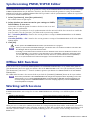
Synchronizing PM5D/DSP5D Editor
When PM5D/DSP5D Editor starts up, the parameter settings on the PM5D/DSP5D itself and the parameter settings
in PM5D/DSP5D Editor may be different. Therefore, you must first match the parameter settings on the PM5D/
DSP5D itself with those in PM5D/DSP5D Editor. This operation is called “synchronization.” Follow the steps below
to synchronize PM5D/DSP5D Editor.
1 Select [Synchronize], then [Re-synchronize].
The window shown at right opens.
2 Select whether you want to transfer your settings to PM5D/
DSP5D Editor, or vice versa.
At this time, the All Libs option determines whether or not Scene and
Library data is synchronized.
If the [Fast Sync] check box is selected, synchronization with the unit itself will be faster. In order to enable this
item, you must select the [Fast Sync] check box in the System Setup window.
PC -> Console (DSP5D):
Tr ansfers the current parameter settings in PM5D/DSP5D Editor to the PM5D/
DSP5D itself.
Console (DSP5D) -> PC:
Tr ansfers the current parameter settings of the PM5D/DSP5D itself to the PM5D/
DSP5D Editor.
3 Click [OK].
Do not operate the PM5D/DSP5D itself while synchronization is in progress.
• When you synchronize with Studio Manager, synchronize will occur between all editors selected in Stu-
dio Manager and the respective hardware units.
• If loading of scene data from an external location is disabled on the unit itself, the Direction will be set to
Console (DSP5D) -> PC. If there is scene data that is set to Read Only, a dialog box will appear when
you click OK, asking whether you want the read-only data to be synchronized as Console (DSP5D) ->
PC, or not synchronized. Your selection will apply to all scene data that is set to Read Only.
Offline Edit Function
If you do not want to synchronize PM5D/DSP5D itself with PM5D/DSP5D Editor, select [Offline Edit] from the
[Synchronization] menu. To apply your off-line edits to the PM5D/DSP5D itself, select [Re-Synchronize] from the
[Synchronization] with the PC -> Console (DSP5D) option to synchronize the PM5D/DSP5D itself with PM5D/
DSP5D Editor.
The Offline Edit function is also activated when you click the [ONLINE]/[OFFLINE] button in the Sync window.
Some effect parameters in the PM5D/DSP5D itself change their displayed values depending on the sam-
pling frequency. If you switch PM5D/DSP5D Editor from OFFLINE to ONLINE, displayed parameter val-
ues may change because PM5D/DSP5D Editor loads the sampling frequency from the PM5D/DSP5D
itself and updates the display.
Working with Sessions
In PM5D/DSP5 Editor, mix settings for an entire PM5D/DSP5D unit, including scene and library data, are called a
Session.
When you save a session in the window of an editor, the settings of only that editor will be saved in a file. Session files
saved by PM5D/DSP5D Editor have a filename extension of “.YSE”. Files in which only the PM5D itself data is saved
(filename extension “.PM5”) can also be handled, allowing you to use a memory card to exchange data with the
PM5D itself.
Creating a new Session
Choose [New Session] from the [File] menu.
Opening a previously saved Session
Choose [Open Session] from the [File] menu.
Saving the current Session
Choose [Save Session] from the [File] menu.
Saving the current Session with a new name
Choose [Save Session As...] from the [File] menu.
NOTE
NOTE

PM5DV2/DSP5D Editor Owner’s Manual
6
If you save a Session in the Studio Manager window, all selected Editor settings are saved in a file with a file extension
of “.YSM.”
Data with the extension “.PM5” that was saved by PM5D version 1 and PM5D Editor (supporting version
1) can also be opened by PM5DV2 Editor.
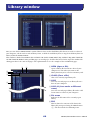
Window operations
You can select and open each window from the [Win-
dows] menu. For the INPUT CH window and Effect Edi-
tor window, use the sub-menu to select the channels or
library you want to see.
In the Library window or Scene window, click the tabs
located at the top of the window to switch between
pages.
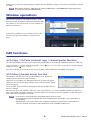
Edit functions
❏
Ch Copy / Ch Paste (channel copy / channel paste) function
The Ch Copy/Ch Paste function copies or pastes the channel that is selected by the [SELECT] button (or [SEL] key.)
Copy can also be executed by using the keyboard’s <Ctrl> ( ) key + <C> key. Paste can also be executed by using the
keyboard’s <Ctrl> ( ) key + <V> key.
Since the Undo data is cleared when you execute Ch Paste, Undo will become unavailable at that point.
❏
Ch Move (channel move) function
The Ch Move function moves the specified channel to the location of
another channel that has the same structure.
When you select Ch Move, the dialog box shown at the right will appear.
When you click the buttons located below Source and Destination, a chan-
nel list will appear.
Select the move Source and move Destination, and click the OK button to
move the channel.
The channels affected by Ch Move will be the same set of channels as selected by [SELECT] button (or [SEL] key).
This is not available for output channels. Undo data will be cleared when you execute Ch Move, so all Undo opera-
tions will become unavailabl at that point.
• If the Source is a paired channel, the channels will be moved as a pair.
• If there are paired channels between the Source and Destination, movement occurs in pairs (units of
two channels).
•Movement will occur in pairs (units of two channels) if parameters of which there is one instance for
every two channels are turned on (also if parameters such as GANG or LINK are on).
NOTE
NOTE

PM5DV2/DSP5D Editor Owner’s Manual
7
Undo/Redo Function
In PM5D/DSP5D Editor, you can cancel the latest operation (Undo) and also cancel the cancellation of the latest
operation (Redo). If you perform an Undo operation twice in a row, you can cancel the two most-recent operations.
If you perform an Undo operation three times in a row, you can cancel the three most-recent operations. In this way,
you can cancel multiple recent operations.
The following table describes how to use the Undo/Redo function.
Please note, however, that after you perform one of the following operations, you cannot successfully undo or redo
any previous operation:
•Operations on the PM5D/DSP5D itself
• Quitting Studio Manager
•Changing the surround mode or pair mode
•Synchronizing with the PM5D/DSP5D itself
•Session operations
•The GEQ [EQ FLAT] button
•Moving the fader positions by changing the GEQ variable width
You cannot Undo or Redo the following operations:
• Edits in the Setup window
• Synchronization
• Opening and closing the windows
• Resizing the windows
• Ch Copy/Ch Paste
• Ch Move
For some functions, there are also other operations that cannot be undone.
For Library and Scene operations, Undo/Redo will apply only to the single preceding operation. You can-
not undo an operation that occurred two or more operations previously. Undo/Redo in these windows can
be performed only using the [UNDO] button in the respective window. Even if you execute a scene recall
from the Sync window, you cannot use a shortcut or menu operation to undo this.
Other Functions
❏
Resetting to the default value (Ctrl ( ) + click)
Move the cursor to a control or a parameter value, then hold down the <Ctrl> ( ) key and click the mouse but-
ton to reset the value to the default (e.g., to reset an Input Channel fader to –
∞
dB, or reset a pan setting to Cen-
ter).
❏
Ctrl ( ) +Shift+Click
Move the cursor to a fader or AUX Send control, then hold down the <Ctrl> ( ) key and <Shift> key and click
the mouse button to reset the value to the nominal level.
Undo
Choose [Undo] from the [Edit] menu.
Redo
Choose [Redo] from the [Edit] menu.
NOTE
NOTE

PM5DV2/DSP5D Editor Owner’s Manual
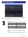
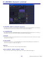
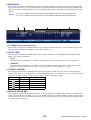
8
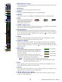
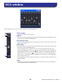
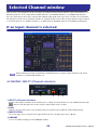
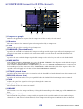
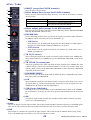
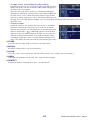
This window displays the parameters of input channels 1–24 or 25–48. The window shows either the channel 1–24
layer or the channel 25–48 layer. To open the other layer’s window, choose the [Windows] menu command [INPUT
CH] and choose “CH1-24” or “CH25-48.”
You can use the [View] menu to choose the parameters that will be displayed in the window.
A Input patch
Here you can select an input source to assign to the input channel, from the following
choices.
*These choices are shown only in PM5D Editor.
B +48V
Switches on/off the phantom power (+48V) of the internal HA (PM5D-RH model and
DSP5D only) or of the external HA (AD8HR, AD824) patched to the input channel.
C HA GAIN
Drag the knob in the screen to adjust the gain of the internal HA (PM5D-RH model
and DSP5D only) or of the external HA (AD8HR, AD824) patched to the input chan-
nel.
NONE No assignment
AD1–AD48 INPUT jacks 1–48
AD1L–AD4R L/R channels of ST IN jacks 1–4
S1-1, S1-2...S4-15, S4-16
Input channels of an I/O card installed in slots 1–4
On the DSP5D, SLOT3 and SLOT4 are assigned
to CASCADE IN/OUT D-SUB.
FX1L, FX1R...FX8L, FX8R L/R outputs of internal effects 1–8
2TR D1L, 2TR D1R...2TR D3L, 2TR D3R L/R channels of 2TR IN DIGITAL jacks 1–3*
2TR A1L, 2TR A1R, 2TR A2L, 2TR A2R L/R channels of 2TR IN ANALOG jacks 1/2*
INPUT CH window
1
2
3

PM5DV2/DSP5D Editor Owner’s Manual
9
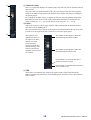
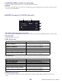
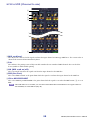
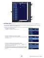
D HPF (High Pass Filter)
Switches the high pass filter on/off. You can drag the numeric value up or down to edit
the cutoff frequency.
E Ø (Phase)
Inverts the phase of the signal after AD conversion.
F INSERT
Switches the INSERT PATCH path between enabled/disabled.
G DIRECT
Switches the output to the DIRECT OUT PATCH port between enabled/disabled.
H GATE
Turns the gate on/off. The indica-
tor immediately below the button
shows the gate’s on/off setting
and the open/closed status.
I COMP (Compressor)
Switches the compressor on/off. When the compressor is on, the GR meter immediately
below the button shows the amount of gain reduction.
J EQ (Equalizer)
Switches the EQ on/off. The graph immediately below the button shows the approxi-
mate response of the EQ. You can drag within the graph to edit the response of the EQ.
To reset the EQ to flat response, hold down the <Ctrl> key ( key) of your computer
keyboard and click the graph.
K DELAY
Switches the delay on/off. You can also edit the delay time by dragging the numeric
value located immediately below the button up or down
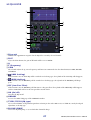
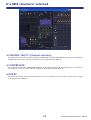
L Channel number
Indicates the input channel number corresponding to this module. You can double-
click this number to open the Selected Channel window for this channel. If you hold
down your computer keyboard’s <Ctrl> key ( key) and double-click this, the Locked
window will open.
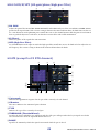
M MIX SEND
The bar graphs in this area indicate the send levels of
the signals sent from the input channel to MIX buses.
You can also adjust the send levels by dragging a bar
graph to left or right.
The bar graph display will change according to the
send position (pre/post) and on/off status of the signal
sent from the input channel to the MIX buses.
•You can turn this on/off by clicking the number at the left.
•For FIXED-type MIX buses, the bar graph is fixed at nominal level (0 dB),
and only the on/off status is shown.
N PAN
Sets the panning of the signal sent from the input channel to the STEREO bus. This
may be BALANCE depending on the PAN mode.
O SELECT
Selects input channel for which you want to perform operations. This is linked with the
INPUT channel strip [SEL] keys on the PM5D panel.
P CH ON (Channel on) button
Switches the input channel on/off. This is linked with the INPUT channel strip CH
[ON] keys on the PM5D panel.
L
O
P
N
M
5
6
7
8
9
J
4
K
Gate= closed
(red)
Gate= open
(green)
Gate= off
Pre/on (green)
Pre/off (green)
Post/off (yellow)
Post/on (yellow)
NOTE

PM5DV2/DSP5D Editor Owner’s Manual
10
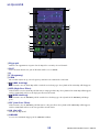
Q Channel name
This is a text box that displays the channel name. You can also edit the channel name in
this text box.
Note that while the channel number (
L) does not change when you switch pairing
mode in the Mixer Setup window, the channel name display will change according to
the pairing mode.
For example if the CH1-24 layer is displayed, and you switch the pairing mode from
Horizontal to Vertical, the channel name indications that had been arranged in the
order of channels 1, 2, 3 ... 24, 25 will change to the order of 1, 3, 5 ... 45, 47.
R Fader
Adjusts the input level of the input channel. This is linked with the INPUT channel
strip faders on the PM5D panel.
The current fader value is shown in the numeric box immediately below the fader. The
level meter at the right of the fader shows the level of the input signal.
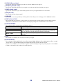
The numbers and
alphabetical letters at
the right of the fader
indicate the DCA
group and mute
groups to which that
channel belongs, and
show the Recall Safe
and Mute Safe status of
the channel.
S CUE
This button cue-monitors the signal of the input channel. This is linked with the
INPUT channel strip [CUE] keys on the PM5D panel. If SOLO is active, this will func-
tion as SOLO.
Q
S
R
The numbers of DCA groups to which this
channel belongs are shown in yellow.
The numbers of mute groups to which this
channel belongs are shown in red.
If this channel is set to Recall Safe, the R
character is shown in orange.
If this channel is set to Mute Safe, the M char-
acter is shown in red.

PM5DV2/DSP5D Editor Owner’s Manual
11
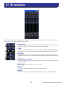
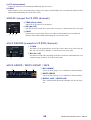
In this window you can view and edit the parameters of ST IN channels 1–4. You can use the [View] menu to choose
the parameters that will be displayed in the window.
A Input patch
Selects the input source that will be assigned to the ST IN channel. The input sources
that can be assigned are the same as for an input channel (➥ p.8).
B +48V
Switches on/off the phantom power (+48V) of the internal HA (PM5D-RH model and
DSP5D only) or of the external HA (AD824, AD8HR) patched to the ST IN channel.
C HA GAIN
Drag the knob in the screen to adjust the gain of the internal HA (PM5D-RH model
and DSP5D only) or of the external HA (AD824, AD8HR) patched to the ST IN chan-
nel.
D HPF (High Pass Filter)
Switches the high pass filter on/off. You can drag the numeric value up or down to edit
the cutoff frequency.
E Ø (Phase)
Inverts the phase of the signal after AD conversion.
F INSERT
Switches the INSERT PATCH path between enabled/disabled.
G DIRECT
Switches the output to the DIRECT OUT PATCH port between enabled/disabled.
ST IN window
5
6
7
1
2
3
4

PM5DV2/DSP5D Editor Owner’s Manual
12
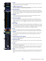
H GATE
Turns the gate on/off. The indicator immediately below the button shows the gate’s on/
off setting and the open/closed status (➥ p.9).
I COMP (Compressor)
Switches the compressor on/off. When the compressor is on, the GR meter immediately
below the button shows the amount of gain reduction.
J EQ (Equalizer)
Switches the EQ on/off. The graph immediately below the button shows the approxi-
mate response of the EQ. You can drag the graph to edit the response of the EQ, or hold
down the <Ctrl> key ( key) of your computer keyboard and click the graph to reset
it to a flat response.
K DELAY
Switches the delay on/off. You can also edit the delay time by dragging the numeric
value located immediately below the button up or down
L Channel number
This is the number of the ST IN channel for this module. You can double-click this
number to open the Selected Channel window for this channel. If you hold down your
computer keyboard’s <Ctrl> key ( key) and double-click this, the Locked window
will open.
M MIX SEND
The send levels of the signals sent from the ST IN channel to the MIX buses are shown
as bar graphs. You can also adjust the send levels by dragging a bar graph to left or right.
The bar graph display will change according to the send position (pre/post) and on/off
status of the signal sent from the ST IN channel to the MIX buses (➥ p.9).
N PAN
Specifies the panning of the signal sent from the ST IN channel to the STEREO bus.
(You can set L and R separately.) This may be BALANCE depending on the PAN mode.
O SELECT
Selects the ST IN channel for which you want to perform operations. (L and R can be
selected separately.) This is linked with the ST IN channel strip [SEL] keys on the
PM5D panel.
P CH ON (Channel on) button
Switches the ST IN channel on/off. This is linked with the ST IN channel strip CH
[ON] keys on the PM5D panel.
Q Channel name
This is a text box that displays the channel name. You can also edit the channel name in
this text box.
R Fader
Adjusts the input level of the ST IN channel. This is linked with the faders of the ST IN
channel strip on the PM5D panel.
The numbers and alphabetical letters at the right of the fader indicate the DCA group
and mute groups to which that channel belongs, and show the Recall Safe and Mute
Safe status of the channel (➥ p.10).
S CUE
This button cue-monitors the signal of the ST IN channel. This is linked with the ST IN
channel strip [CUE] keys on the PM5D panel. If SOLO is active, this will function as
SOLO.
O
Q
N
P
R
S
L
M
8
J
9
K

PM5DV2/DSP5D Editor Owner’s Manual
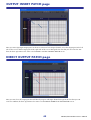
13
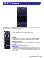
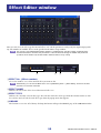
In this window you can view and edit the parameters of FX RTN channels 1–4. You can use the [View] menu to
choose the parameters that will be displayed in the window.
A Input patch
Selects the input source that will be assigned to the FX RTN channel. The input sources
that can be assigned are the same as for an input channel (➥ p.8).
B +48V
Switches on/off the phantom power (+48V) of the internal HA (PM5D-RH model and
DSP5D only) or of the external HA (AD8HR, AD824) patched to the FX RTN channel.
C HA GAIN
Drag the knob in the screen to adjust the gain of the internal HA (PM5D-RH model
and DSP5D only) or of the external HA (AD8HR, AD824) patched to the FX RTN
channel.
D HPF (High Pass Filter)
Switches the high pass filter on/off. You can drag the numeric value up or down to edit
the cutoff frequency.
E Ø (Phase)
Inverts the phase of the signal after AD conversion.
F EQ (Equalizer)
Switches the EQ on/off. The graph immediately below the button shows the approxi-
mate response of the EQ. You can drag the graph to edit the response of the EQ, or hold
down the <Ctrl> key ( key) of your computer keyboard and click the graph to reset
it to a flat response.
FX RTN window
6
1
2
5
3
4

PM5DV2/DSP5D Editor Owner’s Manual
14
G Channel number
This is the number of the FX RTN channel for this module. You can double-click this
number to open the Selected Channel window for this channel. If you hold down your
computer keyboard’s <Ctrl> key ( key) and double-click this, the Locked window
will open.
H MIX SEND
The send levels of the signals sent from the FX RTN channel to the VARI-type MIX
buses are shown as bar graphs (the L/R settings are linked). You can also adjust the send
levels by dragging a bar graph to left or right.
The bar graph display will change according to the send position (pre/post) and on/off
status of the signal sent from the FX RTN channel to the MIX buses (➥ p.9).
I PAN
Specifies the panning of the signal sent from the FX RTN channel to the STEREO bus.
(You can set L and R separately.) This may be BALANCE depending on the PAN mode.
J SELECT
Selects the FX RTN channel for which you want to perform operations. (L and R can be
selected separately.) This is linked with the FX RTN channel strip [SEL] keys on the
PM5D panel.
K CH ON (Channel on) button
Switches the FX RTN channel on/off. This is linked with the FX RTN channel strip CH
[ON] keys on the PM5D panel.
L Channel name
This is a text box that displays the channel name. You can also edit the channel name in
this text box.
M Fader
Adjusts the input level of the FX RTN channel. This is linked with the faders of the FX
RTN channel strip on the PM5D panel.
The numbers and alphabetical letters at the right of the fader indicate the DCA group
and mute groups to which that channel belongs, and show the Recall Safe and Mute
Safe status of the channel (➥ p.10).
N CUE
This button cue-monitors the signal of the FX RTN channel. This is linked with the FX
RTN channel strip [CUE] keys on the PM5D panel. If SOLO is active, this will function
as SOLO.
K
M
N
7
J
9
L
8

PM5DV2/DSP5D Editor Owner’s Manual
15
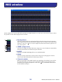
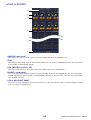
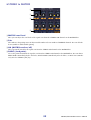
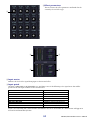
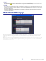
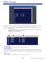
In this window you can view and edit the parameters of MIX channels 1–24. You can use the [View] menu to choose
the parameters that will be displayed in the window.
A EQ (Equalizer)
Switches the EQ on/off. The graph immediately below the button shows the approxi-
mate response of the EQ. You can drag the graph to edit the response of the EQ, or hold
down the <Ctrl> key ( key) of your computer keyboard and click the graph to reset
it to a flat response.
B COMP (Compressor)
Switches the compressor on/off. When the compressor is on, the GR meter immediately
below the button shows the amount of gain reduction.
C INSERT
Switches the INSERT PATCH path between enabled/disabled.
D DELAY
Switches the delay on/off. You can also edit the delay time by dragging the numeric
value located immediately below the button up or down
E Channel number
Indicates the number of the MIX channel corresponding to this module. You can dou-
ble-click this number to open the Selected Channel window for this channel. If you
hold down your computer keyboard’s <Ctrl> key ( key) and double-click this, the
Locked window will open.
MIX window
5
4
1
3
2

PM5DV2/DSP5D Editor Owner’s Manual
16
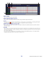
F MTRX (Send level to MATRIX buses)
These bar graphs indicate the send levels of the signals
sent from the MIX channel to each MATRIX bus. You
can also adjust the send levels by dragging a bar graph
to left or right.
The bar graph display will change as follows according
to the send position (pre/post) and on/off status of the
signal sent from the MIX channel to the MATRIX
buses.
You can turn this on/off by clicking the number at left.
G TO ST (To STEREO)
This is an on/off switch for the signal sent from the MIX channel to the STEREO bus.
H PAN
Sets the panning of the signal sent from the MIX channel to the STEREO bus.
I VARI/FIXED
Indicates the type (VARI or FIXED) of the currently selected MIX bus. (This parameter
is for display only. If you want to switch between VARI/FIXED from within PM5D/
DSP5D Editor, use the Mixer Setup window (➥ p.3)
If surround mode is enabled, MIX buses that are assigned as surround buses are dis-
played with the name of the surround channel (L, R, Ls, Rs ...), and the other MIX
buses are displayed as “FIXED.”
J SELECT
Selects the MIX channel for which you want to make settings. This is linked with the
MIX [SEL] keys in the MIX section of the PM5D panel.
K ON
Switches the MIX channel on/off.
L Channel name
This is a text box that indicates the channel name. You can also edit the channel name
within this text box.
M Fader
Adjusts the output level of the MIX channel. The current fader value is shown in the
numeric box immediately below the fader. The level meter at the right of the fader
shows the output level of the signal.
The numbers and alphabetical letters at the right of the fader indicate the DCA group
and mute groups to which that channel belongs, and show the Recall Safe and Mute
Safe status of the channel. (For the significance of the numbers and alphabetical letters,
see ➥ p.10).
N CUE
This button cue-monitors the signal of the MIX channel. This is linked with the MIX
[CUE] keys in the MIX section of the PM5D panel. If SOLO is active, this will function
as SOLO.
7
8
9
N
M
J
K
L
6
Pre/on (green)
Pre/off (green)
Post/off (yellow)
Post/on (yellow)
NOTE

PM5DV2/DSP5D Editor Owner’s Manual
17
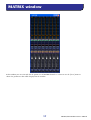
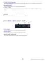
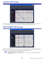
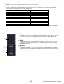
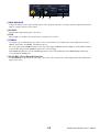
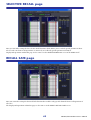
In this window you can view and edit the parameters of MATRIX channels 1–8. You can use the [View] menu to
choose the parameters that will be displayed in the window.
MATRIX window

PM5DV2/DSP5D Editor Owner’s Manual
18
A MIX (Send levels from the MIX channels to the MATRIX bus)
Here you can view and edit the send levels of the signals sent from each MIX channel to
the MATRIX bus. The method of operation and the meaning of the display are the same
as for (
6) MTRX in the MIX window (➥ p.16).
B STEREO (Send levels from the STEREO channels to the MATRIX
bus)
Here you can view and edit the send levels of the signals sent from the STEREO A/B
channels to the MATRIX bus. The method of operation and the meaning of the display
are the same as for (
6) MTRX in the MIX window (➥ p.16).
C Channel number
Indicates the number of the MATRIX channel corresponding to this module. You can
double-click this number to open the Selected Channel window for this channel. If you
hold down your computer keyboard’s <Ctrl> key ( key) and double-click this, the
Locked window will open.
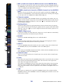
D EQ (Equalizer)
Switches the EQ on/off. The graph immediately below the button shows the approxi-
mate response of the EQ. You can drag the graph to edit the response of the EQ, or hold
down the <Ctrl> key ( key) of your computer keyboard and click the graph to reset
it to a flat response.
E COMP (Compressor)
Switches the compressor on/off. When the compressor is on, the GR meter immediately
below the button shows the amount of gain reduction.
F INSERT
Switches the INSERT PATCH path between enabled/disabled.
G DELAY
Switches the delay on/off. You can also edit the delay time by dragging the numeric
value located immediately below the button up or down
H SELECT
Selects the MATRIX channel for which you want to make settings. This is linked with
the MATRIX [SEL] keys in the MATRIX section of the PM5D panel.
I ON
This switches the MATRIX channel on/off. This is linked with the MATRIX [ON] keys
in the MATRIX section of the PM5D panel.
J Channel name
This is a text box that indicates the channel name. You can also edit the channel name
within this text box.
K Fader
This adjusts the output level of the MATRIX channel. The current fader value is shown
in the numeric box immediately below the fader. The level meter at the right of the
fader shows the output level of the signal.
The numbers and alphabetical letters at the right of the fader indicate the DCA group
and mute groups to which that channel belongs, and show the Recall Safe and Mute
Safe status of the channel. (For the significance of the numbers and alphabetical letters,
see ➥ p.10).
L CUE
This button cue-monitors the signal of the MATRIX channel. This is linked with the
MATRIX [CUE] keys in the MATRIX section of the PM5D panel. If SOLO is active, this
will function as SOLO.
4
6
7
8
9
J
K
L
3
1
2
5

PM5DV2/DSP5D Editor Owner’s Manual
19
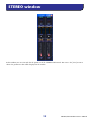
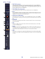
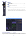
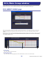
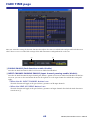
In this window you can view and edit the parameters of the STEREO A/B channels. You can use the [View] menu to
choose the parameters that will be displayed in the window.
STEREO window

PM5DV2/DSP5D Editor Owner’s Manual
20
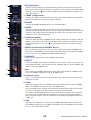
A EQ (Equalizer)
Switches the EQ on/off. The graph immediately below the button shows the approxi-
mate response of the EQ. You can drag the graph to edit the response of the EQ, or hold
down the <Ctrl> key ( key) of your computer keyboard and click the graph to reset
it to a flat response.
B COMP (Compressor)
Switches the compressor on/off. When the compressor is on, the GR meter immediately
below the button shows the amount of gain reduction.
C INSERT
Switches the INSERT PATCH path between enabled/disabled.
D DELAY
Switches the delay on/off. You can also edit the delay time by dragging the numeric
value located immediately below the button up or down. If GANG is turned on, the L/R
delay time will be linked while maintaining their offset value. If GANG is off, the L/R
delay times can be edited individually.
E Channel number
This is the channel number (STEREO A or B) of this module. You can double-click this
number to open the Selected Channel window for this channel. If you hold down your
computer keyboard’s <Ctrl> key ( key) and double-click this, the Locked window
will open.
F MTRX (Send level to MATRIX buses)
Here you can view and edit the send levels of the signals sent from the STEREO A/B
channel to each MATRIX bus. The method of operation and the meaning of the display
are the same as for (
6) MTRX in the MIX window (➥ p.16).
G BALANCE
Adjusts the left/right balance of the STEREO A/B channel.
H SELECT
Selects the STEREO A/B channel for which you want to make settings. (You can specify
L and R independently.) This is linked with the STEREO [SEL] key in the STEREO A/B
channel strip of the PM5D panel.
I ON
This switches the STEREO A/B channel on/off. This is linked with the STEREO [ON]
key in the STEREO A/B channel strip of the PM5D panel.
J Channel name
This is a text box that indicates the channel name. You can also edit the channel name
within this text box.
K Fader
Adjusts the output level of the STEREO A/B channel. This is linked with the STEREO
fader in the STEREO A/B channel strip of the PM5D panel.
The current fader value is shown in the numeric box immediately below the fader. The
level meter at the right of the fader shows the output level of the signal.
The numbers and alphabetical letters at the right of the fader indicate the DCA group
and mute groups to which that channel belongs, and show the Recall Safe and Mute
Safe status of the channel. (For the significance of the numbers and alphabetical letters,
see ➥ p.10).
L CUE
This button cue-monitors the signal of the STEREO A/B channel. This is linked with
the STEREO [CUE] key in the STEREO A/B channel strip of the PM5D panel. If SOLO
is active, this will function as SOLO.
K
L
9
7
8
J
1
3
4
5
6
2
Strona jest ładowana ...
Strona jest ładowana ...
Strona jest ładowana ...
Strona jest ładowana ...
Strona jest ładowana ...
Strona jest ładowana ...
Strona jest ładowana ...
Strona jest ładowana ...
Strona jest ładowana ...
Strona jest ładowana ...
Strona jest ładowana ...
Strona jest ładowana ...
Strona jest ładowana ...
Strona jest ładowana ...
Strona jest ładowana ...
Strona jest ładowana ...
Strona jest ładowana ...
Strona jest ładowana ...
Strona jest ładowana ...
Strona jest ładowana ...
Strona jest ładowana ...
Strona jest ładowana ...
Strona jest ładowana ...
Strona jest ładowana ...
Strona jest ładowana ...
Strona jest ładowana ...
Strona jest ładowana ...
Strona jest ładowana ...
Strona jest ładowana ...
Strona jest ładowana ...
Strona jest ładowana ...
Strona jest ładowana ...
Strona jest ładowana ...
Strona jest ładowana ...
Strona jest ładowana ...
Strona jest ładowana ...
Strona jest ładowana ...
Strona jest ładowana ...
Strona jest ładowana ...
Strona jest ładowana ...
Strona jest ładowana ...
Strona jest ładowana ...
Strona jest ładowana ...
Strona jest ładowana ...
Strona jest ładowana ...
Strona jest ładowana ...
Strona jest ładowana ...
Strona jest ładowana ...
Strona jest ładowana ...
Strona jest ładowana ...
Strona jest ładowana ...
Strona jest ładowana ...
Strona jest ładowana ...
Strona jest ładowana ...
Strona jest ładowana ...
Strona jest ładowana ...
Strona jest ładowana ...
Strona jest ładowana ...
Strona jest ładowana ...
Strona jest ładowana ...
Strona jest ładowana ...
Strona jest ładowana ...
Strona jest ładowana ...
Strona jest ładowana ...
Strona jest ładowana ...
-
 1
1
-
 2
2
-
 3
3
-
 4
4
-
 5
5
-
 6
6
-
 7
7
-
 8
8
-
 9
9
-
 10
10
-
 11
11
-
 12
12
-
 13
13
-
 14
14
-
 15
15
-
 16
16
-
 17
17
-
 18
18
-
 19
19
-
 20
20
-
 21
21
-
 22
22
-
 23
23
-
 24
24
-
 25
25
-
 26
26
-
 27
27
-
 28
28
-
 29
29
-
 30
30
-
 31
31
-
 32
32
-
 33
33
-
 34
34
-
 35
35
-
 36
36
-
 37
37
-
 38
38
-
 39
39
-
 40
40
-
 41
41
-
 42
42
-
 43
43
-
 44
44
-
 45
45
-
 46
46
-
 47
47
-
 48
48
-
 49
49
-
 50
50
-
 51
51
-
 52
52
-
 53
53
-
 54
54
-
 55
55
-
 56
56
-
 57
57
-
 58
58
-
 59
59
-
 60
60
-
 61
61
-
 62
62
-
 63
63
-
 64
64
-
 65
65
-
 66
66
-
 67
67
-
 68
68
-
 69
69
-
 70
70
-
 71
71
-
 72
72
-
 73
73
-
 74
74
-
 75
75
-
 76
76
-
 77
77
-
 78
78
-
 79
79
-
 80
80
-
 81
81
-
 82
82
-
 83
83
-
 84
84
-
 85
85


Yamaha DSP5D Instrukcja obsługi
- Kategoria
- Kontrolery DJ
- Typ
- Instrukcja obsługi
w innych językach
- čeština: Yamaha DSP5D Návod k obsluze
- español: Yamaha DSP5D El manual del propietario
- italiano: Yamaha DSP5D Manuale del proprietario
- Deutsch: Yamaha DSP5D Bedienungsanleitung
- svenska: Yamaha DSP5D Bruksanvisning
- português: Yamaha DSP5D Manual do proprietário
- français: Yamaha DSP5D Le manuel du propriétaire
- 日本語: Yamaha DSP5D 取扱説明書
- Türkçe: Yamaha DSP5D El kitabı
- English: Yamaha DSP5D Owner's manual
- dansk: Yamaha DSP5D Brugervejledning
- русский: Yamaha DSP5D Инструкция по применению
- suomi: Yamaha DSP5D Omistajan opas
- Nederlands: Yamaha DSP5D de handleiding
- română: Yamaha DSP5D Manualul proprietarului
Powiązane dokumenty
-
Yamaha PM5D Instrukcja obsługi
-
-
-
-
-
-
-
-
-