Dynabrade 40610 Operating And Maintenance
- Kategoria
- Elektronarzędzia
- Typ
- Operating And Maintenance

Parts Page Reorder No. PD10•42
Effective December, 2010
Caution: Hand, wrist and arm injury may result from repetitive work, motion and overexposure to vibration.
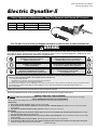
Tool Intent: Dynabrade Electric Dynafile
®
II used to sand, debur, blend and polish; metal, wood, stone, fiberglass or plastic surfaces.
Electric Dynafile
®
II
Model RPM Abrasive Range Offering
40610
11,000 1/4-3/4" x 18-34" Standard
40611
11,000 1/4-3/4" x 18-34" Versatility Kit
Read and understand tool manual before
work starts to reduce risk of injury to
operator, visitors, and tool.
Eye protection must be worn
at all times, eye protection to
conform to ANSI Z87.1.
Respiratory protection to be used when
exposed to contaminants that exceed the
applicable threshold limit values required by law.
Electric shock hazard. Avoid bodily contact with
grounded objects, bodies of water.
Do not damage cord set.
WARNING
Ear protection to be worn when exposure to sound,
exceeds the limits of applicable Federal, State or
local statues, ordinances and/or regulations.
Read and understand this tool manual before operating your tool. Follow all safety rules for the protection of operating
personnel as well as adjacent areas. For safety information, refer to Code of Federal Regulation – CFR 29 Part 1910, –
Safety Requirements and applicable State and Local Regulations.
Practice safety requirements. Work alert,
have proper attire, and do not operate tools
under the influence of alcohol or drugs.
Find The Most Current Offering of Support Documents and Accessories at www.Dynabrade.com
Safety, Operation and Maintenance – Save This Document and Educate All Personnel
Some dust created by sanding, grinding, drilling, and other construction activities contain chemicals known to cause cancer, birth
defects or other reproductive harm. Some examples of these chemicals are:
• Lead from lead-based paints
• Crystalline silica from bricks and cement and other masonry products
• Arsenic and chromium from chemically treated lumber
Your risk from these exposures varies, depending on how often you do this type of work. To reduce your exposure to these chemicals: work in a
well ventilated area, and work with approved safety equipment, such as those dust masks that are specially designed to filter out
microscopic particles.
GENERAL POWER TOOL SAFETY WARNINGS
Read all safety warnings and all instructions.
Failure to follow the warnings and instructions may result in electric shock, fire and/or serious injury.
SAVE ALL WARNINGS AND INSTRUCTIONS FOR FUTURE REFERENCE
The term “power tool” in the warnings refers to your mains-operated (corded) power tool or battery-operated (cordless) power tool.
Work Area safety
1. Keep your work area clean and well lit.
Cluttered or dark areas invite accidents.
2. Do not operate power tools in explosive atmospheres, such as in the presence of flammable liquids, gases, or dust.
Power tools create sparks which ignite
the dust or fumes.
3. Keep children and bystanders away while operating a power tool.
Distractions can cause you to lose control.
Electrical Safety
1. Power tool plugs must match the outlet. Never modify the plug in any way. Do not use any adapter plugs with earthed (grounded) power tools.
Unmodified
plugs and matching outlets will reduce risk of electric shock.
2. Avoid body contact with earthed or grounded surfaces such as pipes, radiators, ranges and refrigerators.
There is an increased risk of electric shock if your body is
earthed or grounded.
3. Do not expose power tools to rain or wet conditions.
Water entering a power tool will increase the risk of electric shock.
4. Do not abuse the cord. Never use the cord for carrying, pulling or unplugging the power tool. Keep cord away from heat, oil, sharp edges or moving parts.
Damaged or entangled cords increase the risk of electric shock.
(continued on next page)
WARNING

2
Electrical Safety (Continued)
5. When operating a power tool outdoors, use an extension cord suitable for outdoor use.
Use of a cord suitable for outdoor use reduces the risk of electric shock.
6. If operating a power tool in a damp location is unavoidable, use a residual current device (RCD) protected supply.
Use of an RCD reduces the risk of electric shock.
Personal Safety
1. Stay alert, watch what you are doing and use common sense when operating a power tool. Do not use power tool while you are tired or under the influence of
drugs, alcohol, or medication.
A moment of inattention while operating power tools may result in serious personal injury.
2. Use personal protective equipment. Always wear eye protection.
Protective equipment such as dust masks, non-skid safety shoes, hard hat, or hearing protection
used for appropriate conditions will reduce personal injury.
3. Prevent unintentional starting. Ensure the switch is in the off-position before connecting to power source and/or battery pack, picking up or carrying the tool.
Carrying power tools with your finger on the switch or energizing power tools that have the switch on invites accidents.
4. Remove any adjusting key or wrench before turning the power tool on.
A wrench or a key left attached to a rotating part of the power tool may result in personal injury.
5. Do not overreach. Keep proper footing and balance at all times.
This enables better control of the power tool in unexpected situations.
6. Dress properly. Do not wear loose clothing or jewelry. Keep your hair, clothing and gloves away from moving parts.
Loose clothes, jewelry or long hair can be
caught in moving parts.
7. If devices are provided for the connection of dust extraction and collection facilities, ensure these are connected and properly used.
Use of dust collection can
reduce dust-related hazards.
Power Tool Use and Care
1. Do not force the power tool. Use the correct power tool for your application.
The correct tool will do the job better and safer at the rate for which it was designed.
2. Do not use the power tool if switch does not turn it on and off.
Any power tool that cannot be controlled with the switch is dangerous and must be repaired.
3. Disconnect the plug from the power source and/or the battery pack from the power tool before making any adjustments, changing accessories, or storing
power tool.
Such preventative safety measures reduce the risk of starting the power tool accidentally.
4. Store idle power tools out of the reach of children and do not allow persons unfamiliar with the power tool or these instructions to operate the power tool.
Power tools are dangerous in the hands of untrained users.
5. Maintain power tools. Check for misalignment or binding of moving parts, breakage of parts and any other condition that may affect the power tool's
operation. If damaged, have the power tool repaired before use.
Many accidents are caused by poorly maintained power tools.
6. Keep cutting tools sharp and clean.
Properly maintained cutting tools with sharp cutting edges are less likely to bind and are easier to control.
7. Use the power tool, accessories and tool bits etc. in accordance with these instructions, taking into account the working conditions and the work to be per
formed.
Use of the power tool for operations different from those intended could result in a hazardous situation.
Service
1. Have your power tool serviced by a qualified repair person using only identical replacement parts. This will ensure that the safety of the power tool is maintained.
SPECIFIC SAFETY RULES
1. Hold power tools by insulated gripping surfaces when performing an operation where the cutting tool may contact hidden wiring or its own cord. Contact with
a “live” wire will make exposed metal parts of the tool “live” and shock the operator.
2. Use a vise or clamping device to restrain work piece.
(See Definitions for label symbols on pg. 3)
TOOL DESCRIPTION
Dynafile II – Is a electric hand tool with a moving narrow belt. Tool is equipped as shown on page 3.
ASSEMBLY and OPERATION INSTRUCTIONS
1. With power source disconnected from tool rotate head to desired position and tighten set screw with hex wrench provided to clamp.
2. Connect power source to tool. Be careful not to depress switch in the process.
3. Hold tool by the motor housing only. One or two hands may be used. Do Not hold tool by head/housing assembly. Keep hands away from all grinding/sanding edges
and moving parts. A side handle is included for two hand operation of tool.
4. Depress switch to start tool. Switch can be locked with button on side of handle, depress switch to release.
5. Adjust belt tracking by turning 95218 Adjustment Knob to the left or right accordingly, so as abrasive belt rides evenly over contact arm.
6. Working off the return path of the abrasive belt will ensure superior tracking.
MAINTENANCE and ACCESSORY CARE INSTRUCTIONS
Important: A preventative maintenance program is recommended whenever portable power tools are used.
•
Use only genuine Dynabrade replacement parts to insure quality. To order replacement parts, specify Model #, Serial # and RPM of your tool.
Routine Preventative Maintenance:
•
Mineral spirits are recommended when cleaning the sanding heads. Do not use on electrical components or clean tool or parts with any solvents or oils containing acids,
esters, ketones, chlorinated hydrocarbons or nitro carbons. Compressed air may be used to remove dirt from electrical components.
•
DO NOT clean or maintain tools with chemicals that have a low flash point (example: WD-40
®
).
•
Tool labels must be kept legible at all times, if not, reorder label(s) and replace. User is responsible for maintaining specification information i.e.:
Model #, S/N, and RPM. (See Assembly Breakdown)
•
Visually inspect plugs and cords for frays, visible damage and signs of deterioration. Damaged or worn components must be replaced by Dynabrade to avoid
a safety hazard.
•
Brush Changing – Unplug tool, remove rear housing and brushes. Install new brushes, and replace rear housing. Run tool for 20 minutes at free speed to seat brushes. Change
brushes every 100 hrs. to ensure proper tool function. After changing brushes it is recommended to replace the right angle gear grease with 95542 Grease.
•
After maintenance is performed on tool check for excessive tool vibration.
•
Check for excessive current leakage at 550 volts with a current leakage checker on all screws and the gear case, if the electrical components have been
disturbed during repair.
Handling and Storage of Tool and Accessories:
•
Use of tool rests, hangers and/or balancers is recommended.
•
DO NOT carry tool by cord.
•
Protect abrasive accessories from exposure to water, solvents, high humidity, freezing temperature and extreme temperature changes.
•
Store accessories in protective racks or compartments to prevent damage.

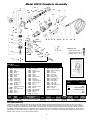
Model 40610 Complete Assembly
3
1 11203 Contact Arm Assembly
2 40759 Belt Housing Assembly
2.1 96334 Plug
2.2 15308 Guide Post
2.3 11040 Spring
2.4 15306 Tension Arm
2.5 95426 Spring
2.6 15309 Shield
2.7 15307 Tension Shaft
2.8 15329 Captive Screw
2.9 15312 Housing Cover
(Includes 15329)
2.10 96335 Hex Nut
2.11 40760 Belt Housing
(Includes 40761, 95442)
2.11.1 95442 Screw
2.11.2 40761 Label - Belt Housing
2.12 95311 Screw
2.13 40029 Cam Lock
2.14 95217 Screw
3 95218 Knob
4 15336 Drive Wheel
5 40724 Screw (4)
6 40762 Spindle Assembly
6.1 40763 Spindle
6.2 40728 Washer
6.3 40729 O-Ring
6.4 40730 Pinion/Gear Set
7 40731 Screw (6)
8 40258 Side Handle
9 40733 Gear Housing Assy.
9.1 40734 Spindle Lock Assy.
10 40735 Nut
11 40736 Screw (2)
12 40737 Armature Assembly
12.1 02649 Bearing
12.2 40738 Bearing Retainer
12.3 40739 Bearing Shield
12.4 01015 Bearing
13 40740 Bearing Seat
14 40741 Fan Baffle
15 40742 Field Coil Assembly
16 40764 Label - Specification
17 40744 Switch
18 40746 Cord Clamp
19 40747 Rear Cover
20 40748 Label - Safety
21 40749 Motor Housing
22 40750 Carbon Brush Set
23 40751 Brush Holder
24 40752 Switch Button
25 40753 Label - Logo
26 40754 Switch Rod
27 40755 Label - Maintenance
28 40756 Cord Sleeve
29 40757 Cord Set
30 95134 Hex Wrench (9/64")
Index Key
No. Part # Description
Wiring Diagram
One Year Warranty
Following the reasonable assumption that any inherent defect which might prevail in a product will become apparent to the user within one year from the date of
purchase, all equipment of our manufacture is warranted against defects in workmanship and materials under normal use and service. We shall repair or replace at
our factory, any equipment or part thereof which shall, within one year after delivery to the original purchaser, indicate upon our examination to have been defective.
Our obligation is contingent upon proper use of Dynabrade tools in accordance with factory recommendations, instructions and safety practices. It shall not apply to
equipment which has been subject to misuse, negligence, accident or tampering in any way so as to affect its normal performance. Normally wearable parts such as
bearings, brushes, gears, etc., are not covered under this warranty.
2.3
1
2.1
2.2
3
2.6
2.7
2.14
2.11
2.10
2.11.2
2.11.1
2.13
2.12
5
6.1
6.3
6.2
6.4
6
8
9.1
9
6.4
11
12.1
12.2
12.3
12.4
13
12
16
17
19
14
18
7
29282726252423222120
15
Grease
7
7
2.9
10
95542 Grease 10 oz.
•
High film strength; excellent
resistance to water, steam, etc.
•
Workable range 0˚ F to 300˚ F.
Model Motor Abrasive Belt Size Max. SFPM Weight Length Height
Number RPM Watts Inch (mm) Voltage Current Phase Frequency (SMPM) Pound (kg) Inch (mm) Inch (mm)
All Models 11,000 680 1/4-3/4 (6-19) W x 18-24 (457-610) L 120 V (AC) 6 amp. 1 60 Hz 2,520 (768) 5 (2.3) 19 (483) 5.5 (140)
30
4
2.8
2.5
2.4
A . . . . . . . . . . . . . . . . . . . . .amperes
Hz . . . . . . . . . . . . . . . . . . . . . . . .hertz
. . . . . . . . . .Class II Construction
RPM . . . . . . . . .revolutions per minute
v . . . . . . . . . . . . . . . . . . . . . . . .volts
w . . . . . . . . . . . . . . . . . . . . . . . .watts
Definitions of Label Symbols
Symbol Description
2

DYNABRADE
®
DYNABRADE, INC.,
8989 Sheridan Drive
•
Clarence, NY 14031-1490
•
Phone: (716) 631-0100
•
Fax: 716-631-2073
•
International Fax: 716-631-2524
© DYNABRADE, INC., 2010 PRINTED IN USA PD10.42_12/10
Visit Our Web Site: www.dynabrade.com Email: [email protected]
1. CSA International
8501 East Pleasant Valley Road
Cleveland, Ohio 4431-5575
Tel: 1 (216) 524-4990
Fax: 1 (216) 642-3463
2. Government Printing Office – GPO
Superintendent of Documents
Attn. New Orders
P.O. Box 371954
Pittsburgh, PA 15250-7954
Tel: 1 (202) 512-1803
Reference Contact Information
Electric Dynafile
®
II
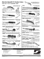
Contact Arms
Optional 40078 Adapter allows use
of 24" long belts; extends reach to
7" when used with contact arm.
Arms for 4" to 12" workable reach.
45 PSI maximum.
Enter channels as
small as 7/16".
Belt Size: 1/2" W x 18" L.
Contact Wheel: 5/8" dia. x 3/8" W, rubber.
Platen: 1/2" wide.
Work on broad areas, leaves
in-line scratch, blend stainless.
11200
11024 steel platen available.
6-3/4" workable reach.
11286
Belt Size: 1/2" W x 24" L.
Contact Wheel: 5/8" dia. x 3/8" W, rubber. Platen: 1/2" wide.
Grind on contact wheel
or platen; has 5-1/4"
workable reach.
11201
Belt Size: 1/2" W x 18" L.
Contact Wheel: 5/16" dia. x 3/8" W, steel.
Platen: 1/2" wide.
11287* Uses 20-1/2" Belts
Belt Size: 5/8" or 3/4" W x 20-1/2" L
Contact Wheel: 3/4" dia. x 5/8" W, rubber. Platen: 3/4" wide.
11304 “The Banana Arm”
Work on broad areas;
leaves in-line scratch;
blend stainless.
Belt Size: 1/2" W x 18" L.
Contact Wheel: 5/8" dia. x 3/8" wide, rubber. Platen: 1/2" wide.
2-1/2"
Rubber
11322 Guide-Cut
Removes raised material within
.020" or less without undercutting.
Guide Wheels
Prevent Undercutting
Belt Size: 1/2" W x 18" L. 60 to 80 grit.
Contact Wheel: 5/8" dia. x 3/8" W, rubber.
11350* “Bus Bar”
Excellent for cleaning oxide
off electrical bus bars. Arm
has a 12" workable reach.
Belt Size: 3/4" W x 34" L.
Contact Wheel: 5/16" dia. x 5/8" W, steel. Platen: 3/4" wide, optional.
11220*, 11300*, 11301*, 11341*
Polish Turbine Blades
Offset design and miniature contact
wheels. 2" strap polish in offset area; pol-
ish turbine blades and other contours.
11203*
Order 11312 for heavy-duty version.
Grind over contact
wheel or platen.
Belt Size: 1/2" W x 18" L.
Contact Wheel: 5/8" dia. x 3/8" W, rubber. Platen: 1/2" wide.
11204 – “Unique Offset Design”
Strap polish is easy with this arm!
Belt Size: 1/4" or 1/2" W x 18" L.
Contact Wheel: 1" dia. x 3/8" W, rubber. Platen: None due to offset design.
11206*
Belt Size: 5/8" or 3/4" W x 18" L.
Contact Wheel: 3/4" dia. x 5/8" wide, rubber. Platen: 3/4" wide.
taperedStrap polish here
Order 11326 for Heavy Duty/Steel Construction version.
11280
Belt Sizes: 11220 uses 5/8" or 3/4" W x 18" L.
All others use 1/2" W x 18" L.
Contact wheels description for each above arm:
11220: 5/16" dia. x 5/8" W, steel. 11300: 1/4" dia. x 3/8" W, steel.
11301: 5/16" dia. x 3/8" W, steel. 11341: 5/16" dia. x 3/8" W, rubber.
Belt Size: 1/4" W x 18" L.
Contact Wheel: 1" dia. x 3/8" wide, urethane, tapered.
Platen: No platen due to offset design.
Grind corners, enter
grooves, strap polish.
-
 1
1
-
 2
2
-
 3
3
-
 4
4


Dynabrade 40610 Operating And Maintenance
- Kategoria
- Elektronarzędzia
- Typ
- Operating And Maintenance
w innych językach
- English: Dynabrade 40610
Inne dokumenty
-
Batavia 400W Weed Sweeper Instrukcja obsługi
-
Triton TSPST450 instrukcja
-
Hitachi G 18SCY Handling Instructions Manual
-
Parkside PFBS160 A1 Operation and Safety Notes
-
Deutz TCD 2011 w Workshop Manual
-
-
-
Meister MWS2400-230 Translation Of The Original Instructions
-
Hitachi CM 7MRU Instrukcja obsługi
-
Parkside 317249 1904 Translation Of The Original Instructions