Willoughby T4 Installation & Operation Manual
- Typ
- Installation & Operation Manual

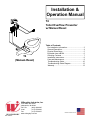
Installation &
Operation Manual
Rev. 8/2017
Willoughby Industries, Inc.
5105 West 78th Street
Indianapolis, IN 46268
Toll Free: (800) 428-4065
Local: (317) 875-0830
Fax: (317) 875-0837
www.willoughby-ind.com
MADE IN THE U.S.A.
Table of Contents
Pre-Installation Information .....................................3
General Description ................................................4
Physical Dimensions ..............................................5
Exploded-view w/BOM ........................................... 6
Checking Contents .................................................7
Installation Instructions ...........................................8
Care and Maintenance ...........................................9
Troubleshooting Guide ......................................... 10
Troubleshooting Guide Diagram ..........................12
Warranty ...............................................................13
T4
Toilet Overfl ow Preventer
w/ Manual Reset
T4
(Manual-Reset)

Installation & Operation Manual
Toilet Overfl ow Preventer w/ Manual Reset
T4
Willoughby Industries, Inc. TOLL FREE (800) 428-4065 ● LOCAL (317) 875-0830 ● FAX (317) 875-0837
Page 2Rev. 8/2017 www.willoughby-ind.com
(Page left intentionally blank)

Installation & Operation Manual
Toilet Overfl ow Preventer w/ Manual Reset
T4
Willoughby Industries, Inc. TOLL FREE (800) 428-4065 ● LOCAL (317) 875-0830 ● FAX (317) 875-0837
Page 3Rev. 8/2017 www.willoughby-ind.com
When installing the Willoughby Industries' Top-4 Overfl ow Preventer w/ Manual Reset:
Before step 1 of the installation instructions, ensure that rough-ins are in the correct location.
The valve assembly, including the spray head, MUST NOT BE connected until after
all lines have been fl ushed to remove the small particles of debris that are inherent
with new construction projects and all chemicals that are used in fl ushing are purged
from the system.
Chemicals used in fl ushing plumbing systems can attack the internal components of
the valve and spray head and severely damage them, so any fl ushing of the system
must be followed by a full fl ushing with pure water to clear any harsh chemicals
remaining in the system. Debris in the system if allowed to enter the valve assembly
and spray head can cause poor performance or outright failure.
Again DO NOT attempt to connect the valve assembly and spray head until after all
fl ushing is complete and pure water is the only media that will be passing through the
system. Damage to the valve assembly or spray head caused by harsh chemicals or
debris will not be covered by the manufacturer's warranty.
Check Rough-In location PRIOR to installation
Flush lines thoroughly PRIOR to hook-up
Check Rough-In location PRIOR to installation
Flush lines thoroughly PRIOR to hook-up
Pre-Installation Information

Installation & Operation Manual
Toilet Overfl ow Preventer w/ Manual Reset
T4
Willoughby Industries, Inc. TOLL FREE (800) 428-4065 ● LOCAL (317) 875-0830 ● FAX (317) 875-0837
Page 4Rev. 8/2017 www.willoughby-ind.com
General Description

Installation & Operation Manual
Toilet Overfl ow Preventer w/ Manual Reset
T4
Willoughby Industries, Inc. TOLL FREE (800) 428-4065 ● LOCAL (317) 875-0830 ● FAX (317) 875-0837
Page 5Rev. 8/2017 www.willoughby-ind.com
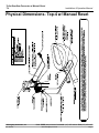
Physical Dimensions- Top-4 w/ Manual Reset

Installation & Operation Manual
Toilet Overfl ow Preventer w/ Manual Reset
T4
Willoughby Industries, Inc. TOLL FREE (800) 428-4065 ● LOCAL (317) 875-0830 ● FAX (317) 875-0837
Page 6Rev. 8/2017 www.willoughby-ind.com
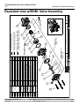
Exploded-view w/BOM- Valve Assembly
ASSEMBLED VIEW
ITEM # SUB-ASSY# PART # DESCRIPTION QTY.
1
980320
380842 FITTING-HOSE BARB T4, 1/4" I.D. TUBE 1
2 980205 AIR SIDE TOP COVER 1
3 980203 TOP 4 RESET BUTTON 1
4 600129 O-RING, #013, BUNA N-70 1
5 980202 TOP 4 RESET SPRING 1
6 980204 TOP 4 RESET RING 1
7 N/A 980616 T4 VACUUM SPRING 1
8
980315
980160 MAGNET CUP & DIAPHRAGM ASSEMBLY 1
9 980132 MAGNET, PNEUMATIC METERING VALVE 1
10 N/A 380802M BODY, MOLDED WI PNEU. MTRG. 1
11 N/A 980127 O-RING M1.5x32 BUNA-70 1
12 N/A 980136 SPRING, WATER SIDE DIAPHRAGM 1
13
980310
980161 BUMPER, WATER SIDE ACTUATOR DISC 1
14 980125 DISK, WATER SIDE ACTUATING 1
15 N/A 980126 BARRIER CUP 1
16 N/A 980426B TOP 4 BASE, SUB-ASSEMBLY 1
17
980305
980128 3-PRONG VALVE SEAT ADAPTOR 1
18 980129 DIAPHRAGM - WATER SIDE - PM/EL 1
19 N/A 980001A #8-32 x 1 1/4" SCREW 4
FRACTIONS:
ANGLE:
EXCEPT AS
3 PLCS:
NOTED
2 PLCS:
1
Indianapolis, Indiana
SIZE:
TRB
MW
TOLERANCES
REF.:
MAT'L:
TITLE / DESC.:
C
1:8
A
PART #:
VALVE ASSEMBLY, T4-MANUAL RESET
9/15/16
SEE BOM
980401T-B
10/12/12
SHEET:
SCALE:
REVISION:
1 OF 1
ORIG.:
REV.:
0.03
0.015
1/32"
Willoughby Industries, Inc.
STANDARD
REPAIR KIT ORDERING #'S ARE
LISTED IN THE EXPLODED VIEW.
DIAPHRAGM
PVK-3
1
2
19
3
4
5
7
6
8
9
10
11
15
16
18
17
KITS ARE NOT SOLD INDIVIDUALLY
PARTS LISTED IN THE PVK REPAIR
13
NOTE:
NOTE:
(PARTS: 3-8)
KIT (PARTS: 18,19
12
980320
TOP4 COVER
ASSEMBLY KIT
TOP4
REBUILD KIT
(PARTS: 3-19)
14
KIT (PART: 15-19)
AVAILABLE IN KIT FORM ONLY. ITEMS
CANNOT BE PURCHASED INDIVIDUALLY.
PVK-5
PVK-2 DIAPHRAGM
ITEMS IN PVK-2, PVK-3, & 980320 ARE
NOTE:
WILLOUGHBY

Installation & Operation Manual
Toilet Overfl ow Preventer w/ Manual Reset
T4
Willoughby Industries, Inc. TOLL FREE (800) 428-4065 ● LOCAL (317) 875-0830 ● FAX (317) 875-0837
Page 7Rev. 8/2017 www.willoughby-ind.com
Check Contents
• Separate all parts from packaging and make sure all parts are accounted for before discarding
any packaging material. If any parts are missing, do not attempt to install T4 Overfl ow Preventer
w/ Manual Reset until you obtain the missing parts.
NOTE: Before beginning installation, all supply, drain and waste piping for the T4 Overfl ow
Preventer w/ Manual Reset must be completed according to specifi ed rough-ins. If you
have not received rough-in details, please contact Willoughby Industries, Inc.
(800) 428-4065
IMPORTANT: Flush all the water supply lines
before making connections.

Installation & Operation Manual
Toilet Overfl ow Preventer w/ Manual Reset
T4
Willoughby Industries, Inc. TOLL FREE (800) 428-4065 ● LOCAL (317) 875-0830 ● FAX (317) 875-0837
Page 8Rev. 8/2017 www.willoughby-ind.com
Installation Instructions
1.) Mount TOP-4 valve with reset button #980401T to the fl ush valve's vacuum breaker tube using
the included clamp. Tighten securely, but noy to the point of deforming the vacuum breaker tube.
Ensure the bracket is mounted on the vacuum breaker tube such that the rubber tee fi tting is
facing downward (see drawing on reverse side).
2.) Connect the two (2) pieces of the tubing th the rubber tee fi tting.
3.) The natural color LDPE tubing #600471 (2 pieces at 36" long) should be connected to the s/s
vacuum generator and bowl sensor. This connection is made with a push-type union connector
#320446 & #320448 (see drawing on reverse side).
Do not shorten this piece of tubing.
4.) The TOP-4 valve is installed in the hydraulic fl ush valve's low pressure line. This line is identifi ed
with a letter "L" on a Sloan
®
fl ush valve and pushbutton for the fl ush valve. After this line has been
connected between the fl ush valve and the pushbutton, cut it at a location that will allow both of
the cut ends to reach the TOP-4 valve. The tube that connects the high pressure (letter "O" on a
Sloan
®
valve) fi ttings on the fl ush valve and pushbutton will remain unchanged.
5.) The line from the fl ush valve (letter "L" on a Sloan
®
valve) connects to the elbow tube fi tting on the
top of the TOP-4 valve and the line from the fl ush valve pushbutton (letter "L" on a Sloan
®
valve)
connects to the straight fi tting on the bottom of the TOP-4 valve (see drawing on reverse side).
6.) Ensure all connections are tight to complete the installation.
Note: if the plastic fi ttings are taken apart for any reason, use ONLY thread tape on the plastic
threads to reseal them. DO NOT USE ANY OTHER THREAD SEALERS OR THREAD
LOCKERS ON THE PLASTIC THREADS. Thread sealers and thread lockers will attack the black
plastic parts. If you have any questions, contact Willoughby Industries at: (317) 638-2381.

Installation & Operation Manual
Toilet Overfl ow Preventer w/ Manual Reset
T4
Willoughby Industries, Inc. TOLL FREE (800) 428-4065 ● LOCAL (317) 875-0830 ● FAX (317) 875-0837
Page 9Rev. 8/2017 www.willoughby-ind.com
Care and Maintenance

Installation & Operation Manual
Toilet Overfl ow Preventer w/ Manual Reset
T4
Willoughby Industries, Inc. TOLL FREE (800) 428-4065 ● LOCAL (317) 875-0830 ● FAX (317) 875-0837
Page 10Rev. 8/2017 www.willoughby-ind.com
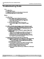
Troubleshooting Guide

Installation & Operation Manual
Toilet Overfl ow Preventer w/ Manual Reset
T4
Willoughby Industries, Inc. TOLL FREE (800) 428-4065 ● LOCAL (317) 875-0830 ● FAX (317) 875-0837
Page 11Rev. 8/2017 www.willoughby-ind.com
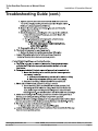
Troubleshooting Guide (cont.)

Installation & Operation Manual
Toilet Overfl ow Preventer w/ Manual Reset
T4
Willoughby Industries, Inc. TOLL FREE (800) 428-4065 ● LOCAL (317) 875-0830 ● FAX (317) 875-0837
Page 12Rev. 8/2017 www.willoughby-ind.com
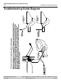
Troubleshooting Guide Diagram

Installation & Operation Manual
Toilet Overfl ow Preventer w/ Manual Reset
T4
Willoughby Industries, Inc. TOLL FREE (800) 428-4065 ● LOCAL (317) 875-0830 ● FAX (317) 875-0837
Page 13Rev. 8/2017 www.willoughby-ind.com
Warranty
Willoughby Industries, Inc. warrants to commercial and institutional purchasers only that each unit will
be free from defects in workmanship and materials under normal use and service upon the following
terms and conditions. The period during which components are warranted is as follows:
1. All other components warranted for 1 year from date of shipment.
This warranty does not cover installation or any other labor charges and does not apply to any
components damaged by accident, abuse, improper installation or improper maintenance. This
warranty does not cover any installation that did not comply with national, state and local building,
plumbing or electrical codes. The warranty is limited to replacing or repairing at manufacturer's option,
transportation charges prepaid by the purchaser, any component or part which upon our inspection
shall be deemed as defective within the limitations of this warranty. The replacement or repair of
defective units as stated in this warranty shall constitute the sole remedy of the purchaser and the
sole liability of Willoughby Industries, Inc. Willoughby Industries, Inc. shall not otherwise be liable
under any indirect damages caused by defects in the repair or replacement thereof.
This warranty only extends to commercial and industrial purchasers and does not extend to any
others, including consumer customers of commercial institutional purchasers. This warranty is in lieu
of all other warranties, expressed or implied, including implied warranty of merchantability or fi tness
for a particular purpose or otherwise.
-
 1
1
-
 2
2
-
 3
3
-
 4
4
-
 5
5
-
 6
6
-
 7
7
-
 8
8
-
 9
9
-
 10
10
-
 11
11
-
 12
12
-
 13
13


Willoughby T4 Installation & Operation Manual
- Typ
- Installation & Operation Manual
w innych językach
- English: Willoughby T4
Inne dokumenty
-
Swiss Madison SM-WT660 Instrukcja obsługi
-
Swiss Madison SM-WT442 Instrukcja instalacji
-
Raven AutoBoom Instrukcja instalacji
-
Samsung DW60M6040BB Instrukcja obsługi
-
Samsung DW60M6050BB Instrukcja obsługi
-
Samsung DW60M5070FS/FA Instrukcja obsługi
-
Honeywell BA295STN Instrukcja obsługi
-
Honeywell BA195 MINIBA Instrukcja obsługi
-
Bradford White M-1-30L6DS Instrukcja obsługi