
BAsic
Automatische Steuerung für Hühnertür
Unité de contrôle automatique pour porte
de poulailler
Automatic Control for Chicken Door
Automatyczne sterowanie do drzwi dla kur
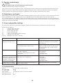
#70540
(DE) Bedienungsanweisung
(FR) Mode d’emploi
(EN) Instructions for use
(PL) Instrukcja obslugi
(CS) Návod k obsluze
(NL) Gebruiksaanwijzing
(IT) Istruzioni per l’uso
(SV) Bruksanvisning
(DA) Brugsanvisning
(FI) Käyttöohje
(SL) Navodila za uporabo
(PT) Instruções de uso
(NO) Bruksanvisning


3
DE Bedienungsanleitung
1. Allgemeines
Die vorliegende Bedienungsanleitung enthält Gebrauchs- und Sicherheitshinweise. Bitte lesen Sie die Anweisungen sorgfältig durch und beachten
Sie die angeführten Vorschriften und Hinweise, bevor Sie das Gerät in Betrieb nehmen. Bedienungsanleitung zum späteren Gebrauch aufbewahren!
2. Bestimmungsgemäße Verwendung
Die automatische Steuerung öffnet und schließt optional erhältliche vertikale Schieber (Art. 70560, 70570, 70580) an Geflügel- und Hühner-
ställen per Seilzug. Die bestimmungsgemäße Umgebung für die Anwendung der automatischen Steuerung ist im Aufenthaltsbereich von Geflü-
geltieren. Eine Anwendung für andere Tierarten ist nicht vorgesehen. Der betriebene Schieber wird automatisch bei einer bestimmten Helligkeit
geöffnet und geschlossen. Bei nicht bestimmungsgemäßem Gebrauch und Eingriffen in das Gerät, insbesondere bei Verwendung nicht dafür
vorgesehener Schieber, erlöschen Haftungsansprüche des Herstellers.
3. Sicherheitshinweise
VORSICHT!
Gefahr von Personen- und Sachschädigung durch unsachgemäßen Gebrauch!
• Stellen Sie sicher, dass keine Tiere oder Kinder in den Gefahrenbereich der bewegten Teile gelangen können.
• Das Gewicht des Schiebers muss angepasst sein.
4. Lieferumfang
• Steuerung
• Lichtsensor
• Montagezubehör
• Bedienungsanleitung
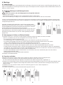
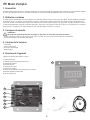
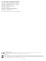
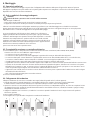
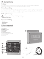
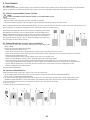
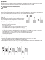
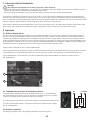
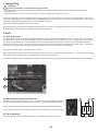
5. Aufbau des Gerätes
Das Gerät besteht aus folgenden Komponenten:
1) Elektronikeinheit
2) Zugschnur für Schieber
3) Lichtsensor
4) Batterieanschluss
5) Batteriehalter
6) Einstelltaste Lichtsensor
7) Anschlussklemmen für externe Taster
8) Lichtsensoranschluss
9) Hinweis-LED
2
4
5
6
8
9
3
7
1

4
6. Montage
6.1 Vorbereitungen
Planen Sie die Montagesituation und insbesondere die Schnurführung von der Tür bis zum Gerät. Messen Sie die Öffnung der Hühnertür aus und
legen Sie eine geeignete Tür mit Führungsschienen bereit. Legen Sie alle Komponenten bereit. Geeignete Schieber und Umlenkrollen finden Sie als
Zubehör in unserem Sortiment.
6.2 Geeigneter Montageort und Montagesituation
VORSICHT!
Gefahr von Personen- und Sachschädigung durch unsachgemäßen Gebrauch!
• Zugschnur nicht verlängern.
• Die Krafteinwirkung durch die Zugschnur kann zu Verletzungen bei Mensch und Tier führen.
• Durch falsche Anordnung ist es möglich, dass Gefahrenbereiche entstehen, die durch Mensch oder Tier erreicht werden.
Suchen Sie für die Elektronikeinheit der automatischen Steuerung einen Montageort mit ebenem und tragfähigem Untergrund. Berücksichtigen
Sie hierbei, dass während des Öffnens des Schiebers eine größere Last auf das Gerät wirkt, als lediglich sein Eigengewicht. Der Montageort muss
vor Regeneinfall geschützt sein.
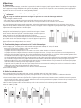
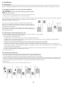
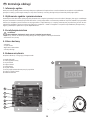
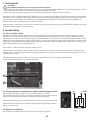
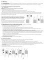
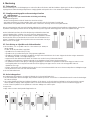
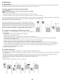
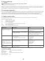
Verwenden Sie gegebenenfalls Umlenkrollen, um bei leichter Verschiebung der
Elektronikeinheit zur Toröffnung die Schnur zu führen. In der Abbildung sind einige
Anordnungsmöglichkeiten gezeigt. Die Elektronikeinheit wird immer in aufrechter
Position mit dem Schnurauslass auf der unteren Seite montiert.
Der Schieber oder die erste Umlenkrolle muss derart montiert sein, dass die Schnur
in gerader Richtung aus dem Gerät herausgeführt wird. Das Gerät bzw. die letzte
Umlenkrolle muss derart montiert sein, dass der Schieber geradlinig nach oben
gezogen wird.
6.3 Befestigung von Schieber und Elektronikeinheit
1) Befestigen Sie das Tor, z.B. einen der in unserem Sortiment erhältlichen Schieber (Art. 70560, Art. 70570, Art. 70580).
Stellen Sie anschließend sicher, dass die nachfolgenden Voraussetzungen erfüllt sind:
• Der Schieber hat ein Gewicht von maximal 2,5 kg.
• Der Schieber bewegt sich in vertikaler Richtung und wird von der Schwerkraft in geschlossene Position versetzt.
• Der Schieber ist leichtgängig. Zum Öffnen des Schiebers wird keine große Kraft benötigt und beim Loslassen des Schiebers
schließt es selbstständig und zuverlässig. Verwenden Sie gegebenenfalls einige Tropfen Öl.
• Die Zugschnur kann ungehindert von der Tür bis zum Gerät geführt werden, ohne dass sie an Fremdkörpern reibt.
• Die Führungsschienen des Schiebers sind fachgerecht montiert, sodass der Schieber die Gebäudeöffnung sicher verschließt.
• Auf dem gesamten Fahrtweg des Schiebers, der beim Öffnungsvorgang durchfahren wird, ist der Abstand des Schiebers zur Gebäudewand
nicht größer als 5mm. Bei geschlossenem Schieber ist die Gebäudeöffnung nach oben hin nicht mehr offen. Es besteht ansonsten die Gefahr,
dass Körperteile eingequetscht werden, wenn der Schieber hochgezogen wird.
• Das Gerät, alle Umlenkrollen und der Schieber befinden sich auf einer Ebene. Die Schnur wird deshalb später nicht an der seitlichen
Begrenzung der Umlenkrollen reiben.
• Alle Umlenkrollen lassen sich ohne großen Widerstand drehen.
2) Befestigen Sie die Elektronikeinheit.
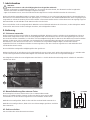
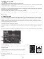
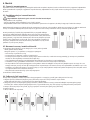
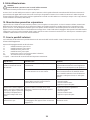
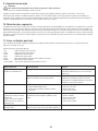
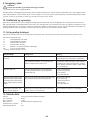
6.4 Zugschnur verbinden
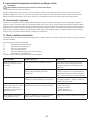
Verbinden Sie die Zugschnur mit dem Schieber. Gehen Sie dabei wie folgt vor (siehe dazu auch die nachfolgende Skizze):
1. Bewegen Sie zunächst die Elektronik in die obere Endstellung. Beleuchten Sie hierzu den Lichtsensor.
Die Schnur wird in der Elektronikeinheit aufgerollt, bis der Knoten für den Endanschlag im Gehäuse angekommen ist.
2. Bewegen Sie anschließend den Schieber in die obere Endstellung (Schieber komplett geöffnet). Bitte lassen Sie für die obere Endposition etwas
Abstand (mind. 50 mm) zu möglichen Endanschlägen oder Hindernissen des Schiebers, damit der Motor rechtzeitig abschaltet, bevor eine
Überlast entsteht.
3. Verbinden Sie die Schnur mit dem Schieber, sodass der Schieber bei gespannter Schnur in oberer Endposition ist.
4. Verknoten Sie die Schnur.
5. Schneiden Sie zuletzt mit einer Schere die überstehenden Längen der Schnur ab.
1 2 3 4 5

5
7. Inbetriebnahme
VORSICHT!
Gefahr von Personen- und Sachschädigung durch unsachgemäßen Gebrauch!
• Tauschen Sie die Batterie in regelmäßigen Abständen aus, da ansonsten die Gefahr besteht, dass die Batterie ausläuft. Ausgelaufene
Batterien und auch das Gerät bitte unverzüglich fachgerecht entsorgen.
• Legen Sie die Batterie erst ein, wenn alle Installationsschritte abgeschlossen sind (einschließlich Einstecken des Lichtsensors).
Um das Gerät mit der notwendigen Energie zu versorgen, legen Sie Batterien (4 x AA, nicht im Lieferumfang enthalten) in den Batteriehalter ein.
Bitte nutzen Sie ausschließlich Batterien mit einer Spannung von 1,5 V. Beachten Sie, dass wiederaufladbare Batterien meist eine geringere Span-
nung aufweisen und von der Steuerung als leer erkannt werden. Leere Batterien werden durch 6 x Blinken der Hinweis-LED angezeigt. Legen Sie
den Batteriehalter ein und verbinden Sie den Batterieanschluss mit der Platine.
Öffnen und Schließen Sie die Tür einige Male durch Abdunkeln und anschließendes Beleuchten des Lichtsensors, um den reibungslosen Betrieb
sicherzustellen. Nun können Sie die Einstellungen vornehmen, wie nachfolgend beschrieben.
8. Bedienung
8.1 Lichtsensor verwenden
Um das automatische Öffnen und Schließen von der Umgebungshelligkeit abhängig zu machen, verbinden Sie den mitgelieferten Lichtsensor
mit dem Gerät und platzieren Sie den Sensor an einem geeigneten Platz. Achten Sie darauf, dass der Sensor das Tageslicht gut erfassen kann.
Der Sensor darf nicht durch Fremdlicht (z.B. künstliches Licht einer Wegbeleuchtung oder aus dem Fenster des Wohnhauses) beeinflusst werden.
Platzieren Sie den Sensor nicht an Fahrtwegen, wo Scheinwerferlicht von vorbeifahrenden Fahrzeugen den Sensor beeinflussen könnte.
Bitte beachten Sie, dass der Lichtsensor erst nach ca. einer Minute auf eine geänderte Helligkeit reagiert. Auf diese Weise wird ein
ungewolltes Öffnen der Tür bei Blitzen verhindert. Die Steuerung erkennt, wenn kein Lichtsensor angeschlossen ist und meldet dies durch
10 x Blinken der Hinweis-LED (9).
Die Tür wird bei der voreingestellten Helligkeit geöffnet bzw. geschlossen.
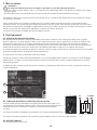
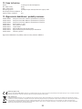
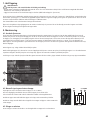
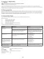
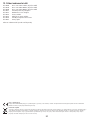
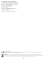
Mit der Einstelltaste (6) im Gerät können Sie die Schaltschwelle des Sensors justieren. Durch Drücken der Einstelltaste für ca. 3 Sekunden merkt
sich die Steuerung die aktuell vorzutreffende Helligkeit und schließt bzw. öffnet ab sofort zu der neu eingestellten Helligkeit.
Das erfolgreiche Einstellen des neuen Helligkeitswertes wird durch 3 x schnelles Blinken der LED bestätigt. Danach sollte die Tür unmittelbar
schließen bzw. öffnen.
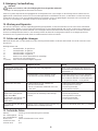
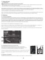
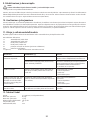
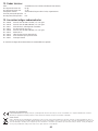
Open Close
Anschlussklemmen
für externe Taster
VUP DOWNV UP DOWN
6
9
8.2 Manuelle Bedienung über externen Taster
Die Steuerung kann mit einem externen Taster (z.B. Art. 70565) bedient werden.
Dieser ist als Zubehör erhältlich. Platzieren Sie den Taster dazu an einem Ort Ihrer Wahl
und verbinden Sie ihn über die dafür vorgesehenen Anschlussklemmen mit dem Gerät:
Wurde die Tür manuell geöffnet, bleibt sie offen und fährt am Abend wieder automatisch zu.
Wurde die Tür manuell geschlossen, bleibt sie bis zum nächsten Morgen geschlossen und öffnet
dann automatisch.
8.3 Gerät ausschalten
Zum Ausschalten des Geräts die Batterien entnehmen.

6
9. Reinigung / Instandhaltung
VORSICHT!
Gefahr von Personen- und Sachschädigung durch unsachgemäßen Gebrauch!
• Vor Beginn der Reinigungsarbeiten die Batterien entnehmen.
Stellen Sie zu jedem Zeitpunkt die Leichtgängigkeit des zu bewegenden Tores sicher. Reinigen Sie die Führungsschienen und benutzen Sie
gegebenenfalls Schmiermittel. Entfernen Sie Schmutz und Gegenstände im Schließbereich des Tores, um den Motor zu schonen und wenig
Schmutz durch die Schnur in das Innere der Elektronikeinheit zu befördern. Prüfen Sie regelmäßig den Zustand der Schnur auf Abrieb und
tauschen Sie sie frühzeitig aus. Verwenden Sie dazu unsere Ersatzschnur (Art. 70552).
10. Wartung und Reparatur
Das Gerät ist wartungsfrei, sollte aber regelmäßig gründlich gereinigt werden. Im Falle eines Defektes muss das Gerät sofort außer Betrieb
genommen werden. Wenden Sie sich im Falle einer Reparatur bitte an einen Elektrofachbetrieb oder schicken Sie das Gerät zur Reparatur an
den Hersteller. Nur Original-Ersatzteile verwenden. Ein zu niedriger Batteriezustand wird von der Steuerung erkannt. Die Hinweis-LED blinkt
bei einem zu niedrigen Batteriezustand 6 x. Die Steuerung schließt am Abend die Tür wie gewohnt und hält sie am morgen geschlossen.
Die Batterien müssen gewechselt werden, damit sie wieder automatisch öffnet und schließt.
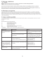
11. Fehler und mögliche Lösungen
Mithilfe der Hinweis-LED kann der aktuelle Status der Steuerung ermittelt werden. Die Hinweis-LED befindet sich auf der Platine im Inneren
des Gehäuses.
Blinkfolge Hinweis-LED:
1 x Automatikmodus, Tür geschlossen
2 x Automatikmodus, Tür geöffnet
3 x Manueller Modus, Tür geschlossen
4 x Manueller Modus, Tür geöffnet
6 x Batterie ist zu schwach (Batteriewechsel notwendig!)
10 x Lichtsensor ist nicht angeschlossen
3 x (schnell) Neuer Lichtsensorwert erfolgreich eingestellt
Fehlerbild Mögliche Ursache Lösung
Tür öffnet und schließt nicht in
Abhängigkeit vom Lichtsensor
Lichtsensor ist nicht richtig eingestellt Stellen Sie den Schwellenwert des Lichtsensors
durch Drücken der Einstelltaste im Gehäuse neu ein
(siehe Kapitel 8.1).
Automatikmodus ist nicht aufgerufen, da mit
einem Externen Taster die Tür betägt wurde.
Die Steuerung wechselt im nächsten Tageszyklus
wieder selbstständig in den Automatikmodus zu-
rück. Die Hinweis-LED blinkt im Automatikmodus
1 x (Tür geschlossen) bzw. 2 x (Tür geöffnet).
Tür fährt nicht nach unten Zu wenig Gewicht am Seil, entweder weil
• die Tür zu leicht ist oder
• die Tür sich verklemmt und deshalb nicht nach
unten zieht
• andere Tür/Schieber verwenden
• Führungsschienen ausrichten
• Schmierung verwenden
• Tür mit Gewicht versehen
Tür fährt nicht ganz auf und
bleibt immer an der gleichen
Stelle stehen oder
Tür fährt nicht mehr ganz zu und
bleibt immer an der gleichen
Stelle stehen
Tür hat ein Hindernis, sodass sie schwergängig ist
(zum Beispiel: Verschmutzung in der Führungs-
schiene)
Tür muss leichtgängig sein.
• Verschmutzung entfernen
• Führungsschienen ausrichten
• Schmierung verwenden
• Tür mit Gewicht versehen
Tür schließt abends, aber öffnet
morgens nicht.
Batterien sind zu schwach (Hinweis-LED blinkt 6 x)
oder haben eine zu niedrige Spannung.
Ersetzen Sie die Batterien durch volle 1,5 V Batterien.
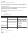
12. Technische Daten
Batterien 4 Stück Typ AA (im Lieferumfang nicht enthalten)
min. Schiebergewicht 0,5 kg
max. Schiebergewicht 2,5 kg
Externe Taster jeweils Schließerkontakt für Auf und Ab
Schutzklasse Gerät III
Schutzart Gerät IP32

7
CE-Konformitätserklärung
Hiermit erklärt die Albert KERBL GmbH, dass sich das in dieser Anleitung beschriebene Produkt/Gerät in Übereinstimmung mit den grundlegenden Anforderungen und
den übrigen einschlägigen Bestimmungen und Richtlinien befindet. Das CE-Zeichen steht für die Erfüllung der Richtlinien der Europäischen Union.
Elektroschrott
Die sachgerechte Entsorgung des Produkts nach deren Funktionstüchtigkeit obliegt dem Betreiber. Beachten Sie die einschlägigen Vorschriften Ihres Landes. Das Gerät
darf nicht mit dem Hausmüll entsorgt werden. Im Rahmen der EU-Richtlinie über die Entsorgung von Elektro-und Elektronikgeräten wird das Gerät bei den kommunalen
Sammelstellen bzw. Wertstoffhöfen kostenlos entgegengenommen oder kann zu Fachhändlern, die einen Rücknahmeservice anbieten, zurückgebracht werden. Die
ordnungsgemäße Entsorgung dient dem Umweltschutz und verhindert mögliche schädliche Auswirkungen auf Mensch und Umwelt.
13. Zubehör / Ersatzartikel
Art. 70560 Schiebetür 220 x 330 mm, inkl. Führungsschienen
Art. 70570 Schiebetür 300 x 400 mm, inkl. Führungsschienen
Art. 70580 Schiebetür 430 x 400mm, inkl. Führungsschienen
Art. 70551 Umlenkrollen, 4er-Pack
Art. 70552 Ersatzschnur mit Perle
Art. 70554 Lichtsensor
Art. 70558 Verlängerungskabel für Lichtsensor
Art. 70559 Selbstverriegelung für Schiebetür
Art. 70565 Externer Taster
Zubehör bzw. Ersatzartikel müssen separat bestellt werden.

8
FR Mode d'emploi
1. Généralités
Le présent mode d'emploi contient les consignes d'utilisation et de sécurité. Veuillez lire soigneusement les instructions avant de mettre l'appareil
en service et respecter les directives et instructions mentionnées. Conservez le mode d'emploi pour toute utilisation ultérieure !
2. Utilisation conforme
La trappe à poules automatique ouvre et ferme grâce à un câble des plaques verticales coulissantes (Réf. 70560, 70570, 70580) pour poulaillers
et bâtiments avicoles. Cesplaques sont disponibles en option. L’environnement adapté à l’utilisation de la trappe à poules automatique est la
zone où les volailles setiennent le plus souvent. Une utilisation pour d’autres espèces animales n’est pas prévue. La plaque actionnée s’ouvre et
se ferme automatiquement à partir d’une certaine luminosité. Tout recours à la garantie du fabricant est exclu en cas d’utilisation non conforme,
d’interventions sur l’appareil et en particulier lors de l’utilisation de plaques non prévues à cet effet.
3. Consignes de sécurité
ATTENTION !
Un usage non conforme peut mettre en danger les personnes et causer des dommages matériels!
• Assurez-vous que les animaux et les enfants ne puissent pas accéder à la zone à risque autour des pièces en mouvement.
• Le poids de la plaque coulissante doit être adapté.
4. Contenu de la livraison
• Commande
• Détecteur de lumière
• Accessoires de montage
• Mode d’emploi
5. Structure de l'appareil
L'appareil se compose des éléments suivants:
1) Unité électronique
2) Corde de traction pour plaque coulissante
3) Détecteur de lumière
4) Raccord des piles
5) Compartiment à piles
6) Détecteur de lumière
7) Bornes de raccordement pour bouton-poussoir externe
8) Raccord du détecteur de lumière
9) LED de signalisation
2
4
5
6
8
9
3
7
1

9
6. Montage
6.1 Préparation
Prévoyez la situation de montage, en particulier le parcours de la corde de la trappe jusqu’à l’appareil. Mesurez l’ouverture de la trappe de pou-
lailler et préparez une trappe adaptée avec des glissières de guidage. Préparez tous les composants. Vous trouverez des plaques appropriées et
des poulies de renvoi en accessoires dans notre gamme de produits.
6.2 Emplacement et conditions de montage appropriés
ATTENTION !
Un usage non conforme peut mettre en danger les personnes et causer des dommages matériels!
• Ne pas allonger la corde de traction.
• La force exercée par la corde de traction peut entraîner des blessures pour les êtres humains ou les animaux.
• Une mauvaise disposition des éléments peut créer des zones à risque accessibles aux êtres humains ou aux animaux.
Pour l’unité électronique de la trappe à poules automatique, recherchez un emplacement de montage situé sur un sol plat et résistant. Tenez
compte du fait que, pendant l’ouverture de la plaque coulissante, la charge qui s’exerce sur l’appareil est plus importante que son propre poids.
L’emplacement de montage doit être à l’abri de la pluie.
Le cas échéant, utilisez les poulies de renvoi pour guider la corde en cas de léger
décalage de l’unité électronique par rapport à l’ouverture de la trappe. Le schéma
montre certaines dispositions possibles. L’unité électronique se monte toujours en
position verticale avec la sortie de la corde située du côté inférieur.
La plaque coulissante ou la première poulie de renvoi doit être installée de manière
que la corde soit dans une direction rectiligne à la sortie de l’appareil. L’appareil ou
la dernière poulie de renvoi doit être installé de manière quela traction exercée sur la
plaque coulissante soit rectiligne dans le sens vertical.
6.3 Fixation de la plaque coulissante et de l’unité électronique
1) Fixez la trappe, p. ex. l’une des plaques coulissantes de notre gamme (réf. 70560, réf. 70570, réf. 70580).
Assurez-vous ensuite que les conditions ci-dessous soient réunies :
• La plaque coulissante pèse maximum 2,5 kg.
• La plaque coulissante se déplace dans le sens vertical et se met en position fermée sous l’effet de la pesanteur.
• La plaque coulissante se déplace facilement. Pour ouvrir la plaque coulissante, il n’est pas nécessaire d’exercer une force importante et
quand on relâche la plaque coulissante, elle se ferme automatiquement de manière fiable. Le cas échéant, utilisez quelques gouttes d’huile.
• La corde de traction relie la trappe à l’appareil sans entrave sans frotter contre des corps étrangers.
• Les rails de guidage de la plaque coulissante sont montés dans les règles si bien que la plaque coulissante ferme correctement l’entrée du bâtiment.
• Sur l‘ensemble du trajet parcouru par la plaque coulissante lors de l‘ouverture, la distance de la plaque coulissante par rapport à la paroi du
bâtiment ne dépasse pas 5 mm. Quand la plaque coulissante est fermée, l‘entrée du bâtiment n’est plus ouverte vers le haut. Lorsque la plaque
coulissante remonte, certaines parties du corps risquent de s’y coincer.
• L’appareil, toutes les poulies de renvoi ainsi que la plaque coulissante se trouvent dans le même plan vertical. Par conséquent la corde ne
frottera pas ensuite contre la limite latérale des poulies de renvoi.
• L’ensemble des poulies de renvoi tournent sans offrir une résistance importante.
2) Fixez l’unité électronique.
6.4 Relier la corde de traction
Reliez la corde de traction à la plaque coulissante. Pour cela, procédez comme suit (voir schéma suivant) :
1. Placez d’abord le système électronique en position finale supérieure.Pour ce faire, dirigez de la lumière sur le détecteur de lumière.
La corde s’enroule dans l’unité électronique jusqu’à ce que le nœud de butée arrive dans le boîtier.
2. Placez ensuite la plaque coulissante en position finale supérieure (plaque coulissante entièrement ouverte). Veuillez laisser pour la position
finale un peu d’espace (min. 50mm) par rapport aux butées ou aux obstacles possibles pour la plaque coulissante afin que le moteur s’arrête
à temps avant qu’une surcharge ne se produise.
3. Reliez la corde à la plaque coulissante de manière que celle-ci soit en position finale supérieure quand la corde est tendue.
4. Faites un nœud à la corde.
5. Sectionnez enfin la partie inutile de la corde avec des ciseaux.
1 2 3 4 5

10
7. Mise en service
ATTENTION !
Un usage non conforme peut mettre en danger les personnes et causer des dommages matériels!
• Remplacez la pile à intervalles réguliers, sinon il y a un risque que la pile soit déchargée. Éliminer sans délai dans les règles les piles usagées
ainsi que l’appareil.
• N’insérez la pile qu’après l’achèvement de toutes les étapes d’installation (y compris l’insertion du détecteur de lumière).
Pour alimenter l’appareil avec l’énergie nécessaire, insérez des piles (4 x AA, non fournies) dans le porte-piles. Insérez le porte-piles et reliez le
raccord des piles à la platine.
Ouvrez et fermez plusieurs fois la trappe en assombrissant puis en éclairant le détecteur de lumière pour vous assurer qu’elle fonctionne
parfaitement. Ensuite, vous pouvez effectuer les réglages comme décrit ci-dessous. Veuillez utiliser exclusivement des piles d’une tension de 1,5
volt. Veuillez noter que les piles rechargeables ont généralement une tension plus faible et qu’elles sont considérées comme vides par l’unité de
contrôle. Les piles vides sont signalées par 6 clignotements consécutifs de la LED de signalisation.
Vouspourrez alors procéder aux réglages de la manière indiquée ci-dessous.
8. Fonctionnement
8.1 Utilisation du détecteur de lumière
Pour faire dépendre l’ouverture et la fermeture automatiques de la luminosité ambiante, reliez le détecteur de lumière fourni à l’appareil
et placez le détecteur à un endroit approprié. Veillez à ce que le détecteur puisse bien capter la lumière du jour. Le détecteur ne doit pas subir
l’influence d’une autre lumière (p. ex. la lumière artificielle provenant d’un éclairage de la voie publique ou d’une fenêtre de l’habitation).
Ne placez pas le détecteur près de la voie publique où le détecteur pourrait subir l’influence de la lumière des phares des véhicules qui passent.
Veuillez noter qu’une minute environ peut s’écouler avant que le détecteur de lumière ne réagisse à un changement de luminosité.
On évite de cette manière une ouverture non désirée en cas d’éclair. L’unité de contrôle constate qu’aucun capteur de luminosité n’est raccordé et
le signale par 10 clignotements consécutifs de la LED de signalisation (9).
La trappe s’ouvre ou se ferme en fonction de la luminosité préréglée.
Vous pouvez modifier le seuil de commutation du détecteur via la touche de réglage (6) dans l’appareil. En actionnant la touche de réglage
pendant environ 3secondes, l’unité de contrôle mémorise la luminosité actuelle et ferme ou ouvre la trappe immédiatement à la nouvelle
luminosité programmée.
Le réglage réussi de la nouvelle valeur de luminosité est confirmé par 3 clignotements rapides de la LED. Ensuite, la trappe doit se fermer ou
s’ouvrir immédiatement.
6
9
Open Close
Bornes de raccordement
pour bouton-poussoir
externe
VUP DOWNV UP DOWN
8.2 Commande manuelle via un bouton-poussoir externe
L’unité de contrôle peut être commandée via un bouton-poussoir externe (Réf. 70565 p. ex.).
Ce bouton-poussoir est disponible comme accessoire. Pour ce faire, placez le bouton-poussoir à
l’endroit de votre choix et raccordez-le à l’appareil via les bornes de connexion prévues
à cet effet:
Si la trappe a été ouverte manuellement, elle reste ouverte et se referme automatiquement le soir.
Si la trappe a été fermée manuellement, elle reste fermée jusqu’au lendemain matin et s’ouvre alors automatiquement.
8.3 Arrêt de l'appareil
Pour éteindre l‘appareil, retirer les piles.

11
9. Nettoyage / maintenance
ATTENTION !
Un usage non conforme peut mettre en danger les personnes et causer des dommages matériels!
• Retirer les piles avant de commencer les travaux de nettoyage.
Assurez-vous à tout moment que la plaque coulissante se déplace facilement. Nettoyez les rails de guidage en utilisant le cas échéant un
lubrifiant. Éliminez les saletés et les objets se trouvant dans la zone de fermeture de la trappe afin de ménager le moteur et de limiter au
maximum la pénétration de saletés à l’intérieur de l’unité électronique à cause de la corde. Vérifiez à intervalles réguliers l’usure de la corde
etremplacez-la avant qu’il ne soit trop tard. Utilisez pour cela notre corde de remplacement (réf. 70552).
10. Maintenance et réparation
L'appareil ne nécessite aucune maintenance, mais doit être soigneusement nettoyé à intervalles réguliers. En cas de défaut, l'appareil doit
immédiatement être mis hors service. Utiliser uniquement despièces de rechange d'origine. L’unité de contrôle détecte un niveau de batterie
trop bas. Un faible niveau de la pile est signalé par 6 clignotements consécutifs de la LED de signalisation. Le soir, l’unité de contrôle ferme la
trappe comme d’habitude, sauf qu’elle la maintient fermée le lendemain matin. Il faut remplacer les piles pour que la trappe s’ouvre et se ferme à
nouveau automatiquement.
11. Erreur et solutions possibles
La LED de signalisation permet notamment de déterminer l’état actuel de l’unité de contrôle. La LED de signalisation se trouve sur la carte de
circuit imprimée à l’intérieur
du boîtier.
Ordre de clignotement de la LED de signalisation:
1 x mode automatique, porte fermée
2 x mode automatique, porte ouverte
3 x mode manuel, porte fermée
4 x mode manuel, porte ouverte
6 x pile trop faible (remplacer la pile par une pile pleine!)
10 x capteur de luminosité non raccordé
3 x (rapidement) réglage réussi de la nouvelle valeur du capteur de luminosité
Image d’erreur Cause possible Solution
La porte ne s’ouvre et ne se ferme
pas en fonction du capteur de
luminosité
Le capteur de luminosité n’est pas réglé
correctement
Réajuster la valeur seuil du détecteur de lumière en
appuyant sur la touche de réglage dans le boîtier
(voir chapitre 8.1).
Le mode automatique n’est pas actif étant donné
que la trappe a été actionnée via un bouton-
poussoir externe.
Lors du cycle journalier suivant, l’unité de contrôle
repasse automatiquement en mode automatique.
La LED de signalisation clignote en mode automati-
que 1 x (trappe fermée) ou 2 x (trappe ouverte).
La porte ne descend pas Trop peu de poids sur la corde, car
• la porte est trop légère, ou
• la porte se coince et ne tire donc pas vers le bas
• utiliser une autre porte/plaque coulissante
• aligner les rails de guidage
• utiliser le graissage
• équiper la porte d’un poids
La porte ne s’ouvre pas complète-
ment et reste toujours bloquée
au même endroit ou la porte ne
se ferme pas complètement et
reste toujours bloquée au même
endroit
La porte a rencontré un obstacle et se déplace
difficilement (par exemple: salissures dans les rails
de guidage)
La porte doit se déplacer facilement.
• éliminer les salissures
• aligner les rails de guidage
• utiliser le graissage
• équiper la porte d’un poids
Porte ferme le soir, mais ne
s’ouvre pas le matin.
Les piles sont trop faibles (6 clignotements consé-
cutifs de la LED de signalisation) ou ne disposent
pas d’une tension suffisante.
Remplacez les piles par des piles pleines de 1,5volt.

12
12. Caractéristiques techniques
Piles 4 unités type AA (non fourni)
Poids min. de la plaque coulissante 0,5kg
Poids max. de la plaque coulissante 2,5kg
Boutons-poussoirs externes contacts de fermeture
pour relèvement et
pour abaissement
Classe de protection de l’appareil III
Classe de protection de l‘appareil IP32
13. Accessoires / articles de rechange
Réf. 70560 Trappe coulissante 220 x 330 mm,
rails de guidage inclus
Réf. 70570 Trappe coulissante 300 x 400 mm,
rails de guidage inclus
Réf. 70580 Trappe coulissante 430 x 400 mm,
rails de guidage inclus
Réf. 70551 Poulies de renvoi, pack de 4
Réf. 70552 Corde de rechange avec perle
Réf. 70554 Sonde de luminosité
Réf. 70558 Rallonge pour détecteur de luminosité
Réf. 70559
Autoverrouillage pour porte de poulailler automatique
Réf. 70565 Bouton externe
Les accessoires ou articles de rechange doivent faire l’objet
d’une commande séparée.
Déclaration de conformité CE
La société Albert KERBL GmbH déclare par la présente que le produit/l'appareil décrit dans le présent mode d'emploi est en conformité avec les exigences fondamentales
et les autres dispositions et directives applicables. La marque CE atteste que les directives de l'Union Européenne sont respectées.
Déchets électriques et électroniques
Il appartient à l’exploitant d'éliminer l'appareil de manière conforme quand il ne fonctionnera plus. Respectez les prescriptions en vigueur de votre pays. Il ne faut pas
éliminer l'appareil avec les ordures ménagères. Dans le cadre de la directive européenne sur l'élimination des appareils électriques et électroniques usagés, l'appareil
estrepris gratuitement par le centre de collecte municipal ou les déchetteries, ou alors il peut être rapporté à un revendeur spécialisé proposant un service de reprise.
Une élimination réglementaire protège l'environnement et empêche d'éventuelles conséquences nocives sur les hommes et l'environnement.

13
EN Operating instructions
1. General
These operating instructions comprise instructions for use and safety information. Please read the instructions carefully and note the regulations
and relevant information before putting the device into operation. Please keep these operating instructions in a safe place for later use!
2. Correct use
The automatic chicken door opens and closes optionally available vertical sliders (ref. no. 70560, 70570, 70580) on poultry and chicken coops
via a cable pull. The correct environment for using the automatic chicken door is one in which poultry are kept. It is not intended for use with any
other type of animal. The slider automatically opens and closes at a specified level of brightness. The manufacturer‘s warranty and liabilities are
invalidated if the device is used incorrectly or tampered with, especially if an unapproved slider is used.
3. Safety instructions
CAUTION!
Risk of physical injury and material damage if used incorrectly!
• Ensure that no animals or children are able to enter the hazardous zone of moving parts.
• The weight of the slider must be adjusted.
4. Supplied package
• control unit
• light sensor
• installation accessories
• operating instructions
5. Setup of the device
The device consists of the following components:
1) Electronics unit
2) Pull cord for slider
3) Light sensor
4) Battery connection
5) Battery holder
6) Light sensor
7) Connecting terminals for external buttons
8) Light sensor connection
9) Indicator LED
2
4
5
6
8
9
3
7
1

14
6. Installation
6.1 Preparations
Plan the installation site and in particular the routing of the cable from the door to the device. Measure the opening of the chicken door and
provide a suitable door with guide rails. Get all of the components ready. You will find suitable sliders and pulleys in our range of accessories.
6.2 Suitable installation site and installation conditions
CAUTION!
Risk of physical injury and material damage if used incorrectly!
• Do not extend the pull cord.
• The impact of force from the pull cord can cause injury to humans and animals.
• Incorrect setup can create hazardous zones for humans or animals.
For the automatic chicken door's electronics unit, find an installation site with a level and stable base. Be aware that when the slider is opened, a
higher load is exerted on the device than its own weight alone. The installation site
must be protected from the ingress of rain.
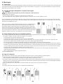
If necessary, use the pulleys to guide the cord with slight movement of the
electronics unit towards the door opening. The illustration shows a number of
setup options. The electronics unit is always installed in an upright position with
the cord outlet on the underside.
The slider or the first pulley must be installed so that the cord is straight when
itexits the device. The device or the last pulley must be installed so that the slider
is pulled straight upwards.
6.3 Attaching the slider and electronics unit
1) Attach the door, e.g. to one of the sliders available in our range (Art. 70560, Art. 70570 , 70580).
Then ensure that the following requirements are met:
• The slider weighs a maximum of 2.5 kg.
• The slider moves in a vertical direction and is placed in the closed position by gravity.
• The slider moves easily. No great amount of force is required to open the slider, and when the slider is released it closes independently
andreliably. If necessary, use a few drops of oil.
• The pull cord can be routed unhindered from the door to the device without chafing against foreign bodies.
• The guide rails of the slider are precision-installed so that the slider closes the opening of the coop reliably.
• The distance from slider to building wall does not exceed 5 mm throughout the slider’s entire movement path, which is travelled during
opening. When the slider is closed, the building‘s opening is no longer open at the top. There would otherwise be a risk that body parts could
be crushed when the slider is pulled up.
• The device, all pulleys and the slider are all on one level. The cord will then not chafe against the side limit of the pulleys later on.
• All pulleys can be turned without a high degree of resistance.
2) Fasten the electronics unit.
6.4 Connecting the pull cord
Connect the pull cord to the slider. To do this, proceed as follows (see also the following sketch):
1. First move the electronics to the upper terminal position. For this, illuminate the light sensor.
The cord is rolled up in the electronics unit until the knot for the end stop arrives at the housing.
2. Then move the slider to the upper terminal position (slider fully open). Please leave a little distance (min. 50 mm) between the slider's possible
terminal stopsor obstacles for the upper terminal position so that the motor has enough time to switch off before any excess load develops.
3. Connect the cord to the slider so that the slider is in the upper terminal position when the cord is taut.
4. Knot the cord.
5. Finally, using a pair of scissors, cut off the excess length of the cord.
1 2 3 4 5

15
7. Bringing into operation
CAUTION!
Risk of physical injury and material damage if used incorrectly!
• You should replace the battery at regular intervals since otherwise there is a risk that the battery mayleak. Spent batteries and the device itself
should be disposed of properly without delay.
• Insert the battery only after all steps of the installation have been completed (including insertion of the light sensor).
To provide the device with the energy required, place batteries (4 x AA, not included in the delivery) in the battery holder. Please only use batteries
with a voltage of 1.5 V. Be aware that rechargeable batteries generally have a lower voltage, causing the control to report them as being empty.
Empty batteries are shown by the indicator LED flashing 6 x.
Insert the battery holder, and use the battery connector to connect it to the circuit board.
To ensure that the system is operating smoothly, open and close the door a few times by shading and then illuminating the light sensor. You can
now make the relevant settings, as described below.
8. Operation
8.1 Using the light sensor
To make automatic opening and closing dependent on the ambient brightness, connect the supplied light sensor with the device and position
the sensor in a suitable place. Ensure that the sensor is easily able to detect daylight. The sensor must not be influenced by other sources of
light (e.g. artificial light from a street lamp or from a house window). Do not position the sensor on roadways where light from the headlights
of passing cars may influence the sensor. Please note that approx. one minute may elapse before the light sensor responds to a change in
brightness. This prevents accidental opening of the door in the event of lightning. The control recognises when no light sensor is attached and
indicates this by making the indicator LED flash 10 x (9).
The door opens and closes at the pre-set level of brightness.
You can adjust the sensor‘s switching threshold using the adjustment button (6) in the device. When the adjustment button is pressed for approx.
3 seconds, the controller records the current brightness level, and henceforth uses the new brightness setting to trigger opening and closing of
the door.
The LED flashes quickly 3 times to confirm that the new brightness level has been set successfully. The door should then close or open immediately.
6
9
Open Close
Connecting terminals
for external buttons
VUP DOWNV UP DOWN
8.2 Manual operation via external button:
The controller can be operated using an external sensor (e.g. item 70565). This is available as an
accessory. For this, position the sensor in a location of your choice and connect it to the device via
the terminals provided:
If the door was opened manually, it remains open, and closes again in the evening.
If the door was closed manually, it remains closed until the next morning and then
opens automatically.
8.3 Switching the device off
To switch off the device, disconnect the connecting cable from the socket and remove
the batteries.

16
9. Cleaning / maintenance
CAUTION!
Risk of physical injury and material damage if used incorrectly!
• Remove the batteries before starting the cleaning tasks.
Check the easy running of the moving door at all times. Clean the guide rails and use lubricant if necessary. Remove dirt and any objects from
thedoor's closing area in order to protect the motor and avoid transporting dirt via the cord into the inside of the electronics unit. Regularly
checkthe condition of the cord for wear and replace it in good time. Use our replacement cord to do this (ref.no. 70552).
10. Maintenance and repair
The device does not require maintenance, but should be thoroughly cleaned at regular intervals. In the event of a fault, the device must be taken
out of use immediately. If a repair is required, please contact a qualified electrician or send the device for repair to the manufacturer.
Only use original spare parts. The controller recognises when the battery charge is too low. The indicator LED flashes 6 x when the battery level
is too low. The controller closes the door in the evening as usual, and keeps it closed in the morning. The batteries must be changed in order that
the door opens and closes automatically.
11. Errors and possible solutions
The current status of the control can be determined from the indicator LED. The indicator LED is located on the PCB inside the housing.
Indicator LED flash sequence:
1 x Automatic mode, door closed
2 x Automatic mode, door open
3 x Manual mode, door closed
4 x Manual mode, door open
6 x Battery is too weak (battery change required!)
10 x Light sensor is not connected
3 x (fast) New light sensor value set successfully
Error pattern Possible cause Solution
Door does not open and close
depending on the light sensor
Light sensor is not set properly Set the threshold value for the light sensor by
pressing the setting button in the casing back in
(see section 8.1).
Automatic mode is not activated, because the door
was actuated through an external sensor.
In the next day cycle, the controller returns auto-
matically to automatic mode. The indicator LED
flashes in automatic mode 1 x (door closed) or
2 x (door open).
Door does not move down Too little weight on the rope, either because
• the door is too light or
• the door is jammed and does not therefore
move down
• use other door/slider
• align guide rails
• use lubrication
• add weight to door
Door does not fully move up and
always remains stationary at the
same point, or door does not fully
move down and always remains
stationary at the same point
Door is obstructed, making it difficult to move
(for example: Dirt in the guide rail)
Door must be smooth-running.
• remove dirt
• align guide rails
• use lubrication
• add weight to door
The door closes in an evening,
but does not open in a morning.
Batteries are too weak (indicator LED flashes 6 x)
or their voltage is too low.
Replace the batteries with full 1.5 V batteries.
12. Technical data
Batteries 4 x type AA (not included in delivery)
min. slider weight 0.5 kg
max. slider weight 2.5 kg
External buttons A normally open contact each for Up and Down
Device protection class III
Device protection type IP32

17
CE declaration of conformity
Albert KERBL GmbH hereby declares that the product / device described in these instructions complies with the fundamental requirements and other relevant
stipulationsand regulations. The CE mark confirms compliance with the Directives of the European Union.
Electrical waste
It is up to the operator to dispose of the product responsibly after its useful life in accordance with local regulations. Consult the relevant regulations for your country.
The device must not be disposed of in household waste. Under the terms of the EU Directive on the disposal of old electrical and electronic equipment, the device can
betaken to local authority-run refuse sites or recycling plants free of charge, or returned to dealers who offer a returns service. Correct disposal protects the environment
and prevents any possible harmful impacts on humans and the environment.
13. Accessories / replacement articles
Réf.no. 70560 Sliding door 220 x 330 mm, incl. guide rails
Réf.no. 70570 Sliding door 300 x 400 mm, incl. guide rails
Réf.no. 70580 Sliding door 430 x 400 mm, incl. guide rails
Réf.no. 70551 Pulleys, pack of 4
Réf.no. 70552 Replacement cord with bead
Réf.no. 70554 Light sensor
Réf.no. 70558 Extension Cable for Light Sensor
Réf.no. 70559 Self-locking for automatic chicken door
Réf.no. 70565 External Button
Accessories and replacement articles must be ordered separately.

18
PL Instrukcja obsługi
1. Informacje ogólne
Niniejsza instrukcja obsługi zawiera informacje dotyczące użytkowania i bezpieczeństwa. Przed uruchomieniem urządzenia należy dokładnie
przeczytać instrukcję i przestrzegać zawartych w niej zasad i informacji. Instrukcję obsługi należy zachować do późniejszego użytku!
2. Użytkowanie zgodnie z przeznaczeniem
Automatyczne drzwi do kurnika wykorzystują linkę do otwierania i zamykania pionowych zasuw w kurnikach (dostępne jako opcja). Prawidłowym
miejscem zastosowania automatycznych drzwi do kurnika są strefy pobytu drobiu. Zastosowanie produktu w miejscach hodowli innych gatunków
zwierząt jest niezgodne z przeznaczeniem. Zasuwy wyposażone wnapęd otwierają się izamykają automatycznie przy określonej jasności. W razie
użytkowania niezgodnie z przeznaczeniem oraz ingerencji w urządzenie – chodzi w szczególności o używanie nieprzewidzianej do tego zasuwy –
wygasają zobowiązania producenta z tytułu odpowiedzialności.
3. Zasady bezpieczeństwa
OSTROŻNIE!
Nieprawidłowe użytkowanie grozi urazami i szkodami materialnymi!
• Upewnić się, że dzieci ani zwierzęta nie mają dostępu do strefy zagrożenia ruchomych elementów.
• Dostosować masę zasuwy.
4. Zakres dostawy
• Sterownik
• Czujnik światła
• Wyposażenie montażowe
• Instrukcja obsługi
5. Budowa urządzenia
Urządzenie składa się z następujących komponentów:
1) Zespół elektroniki
2) Linka napędowa zasuwy
3) Czujnik światła
4) Przyłącze baterii
5) Uchwyt baterii
6) Czujnika światła
7) Zaciski przyłączeniowe do zewnętrznych przycisków
8) Przyłącze czujnika światła
9) Dioda wskaźnikowa
2
4
5
6
8
9
3
7
1

19
6. Montaż
6.1 Czynności przygotowawcze
Zaplanować montaż, awszczególności przebieg linki od drzwi do urządzenia. Wymierzyć otwór na drzwi do kurnika iprzygotować odpowiednie
drzwi zprowadnicami szynowymi. Przygotować wszystkie elementy. Odpowiednie zasuwy ikrążki zwrotne są dostępne wnaszej ofercie jako
akcesoria.
6.2 Prawidłowe miejsce i warunki montażu
OSTROŻNIE!
Nieprawidłowe użytkowanie grozi urazami i szkodami materialnymi!
• Nie przedłużać linki napędowej.
• Siła linki napędowej może spowodować urazy u ludzi i zwierząt.
• Nieprawidłowe rozmieszczenie elementów może spowodować powstanie stref zagrożenia, do których mogą wejść ludzie lub zwierzęta.
Moduł elektroniki automatycznych drzwi do kurnika zamontować na równym, nośnym podłożu. Należy przy tym pamiętać, że podczas otwierania
zasuwy na urządzenie oddziałuje obciążenie większe niż jego masa własna. Miejsce montażu musi być chronione przed deszczem.
W razie potrzeby użyć krążków, aby poprowadzić linkę w przypadku lekkiego
przesunięcia modułu elektroniki względem drzwi. Na ilustracjach przedstawiono
kilka możliwości rozmieszczenia elementów. Zespół elektroniki należy montować w
pozycji pionowej, z wyjściem linki skierowanym w dół. Zasuwę lub pierwszy krążek
zwrotny należy zamontować w taki sposób, aby linka wychodziła z urządzenia w
linii prostej. Urządzenie lub ostatni krążek zwrotny zamontować tak, aby zasuwa
podnosiła się w linii prostej do góry.
6.3 Mocowanie zasuwy i modułu elektroniki
1) Zamocować drzwi lub jedną z zasuw dostępnych w naszej ofercie (produkt
70560, produkt 70570, 70580).
Następnie upewnić się, że spełnione są następujące wymagania:
• Masa zasuwy nie przekracza 2,5 kg.
• Zasuwa porusza się pionowo i zamyka się grawitacyjnie.
• Zasuwa pracuje bez oporu. Do otwarcia zasuwy nie jest konieczna duża siła, a zwolnienie zasuwy powoduje jej samoczynne i prawidłowe
zamknięcie. W razie potrzeby zastosować kilka kropel oleju.
• Linka napędowa przebiega bez przeszkód od drzwi do urządzenia, bez kontaktu z innymi przedmiotami.
• Prowadnice zasuwy są prawidłowo zamontowane, tak że zasuwa skutecznie zamyka wejście do budynku.
• Na całym odcinku ruchu wykonywanego przez zasuwę podczas otwierania odległość zasuwy od ściany budynku wynosi nie więcej niż 5 mm.
Powyżej zamkniętej zasuwy nie może być wolnej przestrzeni. W przeciwnym razie otwarcie zasuwy może spowodować zmiażdżenia części ciała.
• Urządzenie, wszystkie krążki zwrotne i zasuwa znajdują się na tym samym poziomie. Dzięki temu podczas eksploatacji linka nie będzie ocierać
się o ograniczniki boczne na krążkach zwrotnych.
• Wszystkie krążki zwrotne obracają się bez większego oporu.
2) Zamocować moduł elektroniki.
6.4 Podłączenie linki napędowej
Połączyć linkę napędową z zasuwą. W tym celu należy postępować w następujący sposób (patrz także poniższe ilustracje):
1. Najpierw przesunąć elektronikę do górnej pozycji krańcowej. W tym celu należy naświetlić czujnik światła.
Zespół elektroniki zwija linkę, aż węzeł ograniczający dotrze do obudowy.
2. Następnie przesunąć zasuwę do górnej pozycji krańcowej (całkowite otwarcie zasuwy). Pozostawić odległość zapasową górnej pozycji
krańcowej (min. 50 mm) od potencjalnego ogranicznika, czy przeszkód zasuwy, aby silnik wyłączył się przed powstaniem przeciążenia.
3. Doczepić do zasuwy linkę w taki sposób, by po jej naprężeniu zasuwa była w górnej pozycji krańcowej.
4. Zawiązać węzeł.
5. Odciąć nadmiar linki nożyczkami.
1 2 3 4 5

20
7. Uruchomienie
OSTROŻNIE!
Nieprawidłowe użytkowanie grozi urazami i szkodami materialnymi!
• Mimo to należy wymieniać baterie w regularnych odstępach czasu. W przeciwnym wypadku mogłyby z nich wyciec elektrolity. Baterie, z których
wyciekły elektrolity, oraz urządzenie należy niezwłocznie zutylizować zgodnie z przepisami.
• Baterie należy włożyć dopiero po zakończeniu wszystkich etapów montażu (łącznie z podłączeniem czujnika światła).
Aby zapewnić zasilanie urządzenia energią, włożyć baterie (4 x AA, nie są dostarczane w komplecie) do uchwytu baterii. Należy stosować wyłącznie
baterie o napięciu 1,5 V. Należy brać pod uwagę, że baterie przeznaczone do wielokrotnego ładowania odznaczają się zwykle niższym napięciem i
są wykrywane przez układ sterowania jako rozładowane. O rozładowanych bateriach informuje 6-krotne miganie informacyjnej diody LED.
Umieścić uchwyt baterii w urządzeniu i połączyć złącze baterii z płytką.
Kilka razy otworzyć i zamknąć drzwi, przesłaniając i naświetlając naprzemiennie czujnik światła, aby sprawdzić prawidłowe działanie. Teraz można
wprowadzić ustawienia zgodnie zponiższym opisem.
8. Sposób obsługi
8.1 Użycie czujnika światła
Aby otwieranie i zamykanie uzależnić od oświetlenia otoczenia, do urządzenia należy podłączyć dostarczony czujnik światła i umieścić go we
właściwym miejscu. Należy zwrócić uwagę na to, by czujnik mógł dobrze rejestrować światło dzienne. Należy wykluczyć oddziaływanie innych
źródeł światła na czujnik (np. sztuczne oświetlenie drogi czy światło z okien domu). Nie umieszczać czujnika przy drodze, gdzie mogłoby na niego
oddziaływać światła przejeżdżających pojazdów. Należy pamiętać, że czujnik światła reaguje na zmianę oświetlenia dopiero po ok. minucie. Dzięki
temu błyskawice nie powodują niezamierzonego otwarcia drzwi. Układ sterowania wykrywa brak podłączenia czujnika światła i informuje o tym
poprzez 10-krotne miganie informacyjnej diody LED (9).
Drzwi otwierają się lub zamykają przy ustawionej wstępnie jasności.
Próg przełączania czujnika można ustawić za pomocą przycisku ustawień (6) w urządzeniu. Po naciśnięciu i przytrzymaniu przycisku do zmiany
ustawień przez ok. 3 sekundy sterownik zapamiętuje aktualny poziom jasności i od tej chwili zamyka lub otwiera wejście po wykryciu nowo usta-
wionego poziomu jasności.
Prawidłowo zakończone ustawianie nowej wartości jasności jest potwierdzane przez 3-krotne szybkie miganie diody LED.
Bezpośrednio po tym drzwi powinny się zamknąć lub otworzyć.
6
9
Open Close
Zaciski przyłączeniowe
do zewnętrznych przy-
cisków
VUP DOWNV UP DOWN
8.2 Ręczne sterowanie urządzeniem za pomocą zewnętrznego przycisku
Sterownik można obsługiwać za pomocą przycisku zewnętrznego (np. art. 70565).
Jest on dostępny jako akcesorium. W tym celu należy zamontować przycisk w wybrany miejscu
ipodłączyć w urządzeniu do przeznaczonych do tego zacisków przyłączeniowych:
Jeżeli drzwi zostaną otwarte ręcznie, pozostaną otwarte i zamkną się automatycznie wieczorem.
Jeżeli drzwi zostaną zamknięte ręcznie, pozostaną zamknięte do następnego ranka i wówczas
otworzą się automatycznie.
8.3 Wyłączanie urządzenia
W celu wyłączenia urządzenia należy wyciągnąć wtyczkę z gniazdka i wyjąć baterie.
Strona się ładuje...
Strona się ładuje...
Strona się ładuje...
Strona się ładuje...
Strona się ładuje...
Strona się ładuje...
Strona się ładuje...
Strona się ładuje...
Strona się ładuje...
Strona się ładuje...
Strona się ładuje...
Strona się ładuje...
Strona się ładuje...
Strona się ładuje...
Strona się ładuje...
Strona się ładuje...
Strona się ładuje...
Strona się ładuje...
Strona się ładuje...
Strona się ładuje...
Strona się ładuje...
Strona się ładuje...
Strona się ładuje...
Strona się ładuje...
Strona się ładuje...
Strona się ładuje...
Strona się ładuje...
Strona się ładuje...
Strona się ładuje...
Strona się ładuje...
Strona się ładuje...
Strona się ładuje...
Strona się ładuje...
Strona się ładuje...
Strona się ładuje...
Strona się ładuje...
Strona się ładuje...
Strona się ładuje...
Strona się ładuje...
Strona się ładuje...
Strona się ładuje...
Strona się ładuje...
Strona się ładuje...
Strona się ładuje...
Strona się ładuje...
Strona się ładuje...
Strona się ładuje...
Strona się ładuje...
-
 1
1
-
 2
2
-
 3
3
-
 4
4
-
 5
5
-
 6
6
-
 7
7
-
 8
8
-
 9
9
-
 10
10
-
 11
11
-
 12
12
-
 13
13
-
 14
14
-
 15
15
-
 16
16
-
 17
17
-
 18
18
-
 19
19
-
 20
20
-
 21
21
-
 22
22
-
 23
23
-
 24
24
-
 25
25
-
 26
26
-
 27
27
-
 28
28
-
 29
29
-
 30
30
-
 31
31
-
 32
32
-
 33
33
-
 34
34
-
 35
35
-
 36
36
-
 37
37
-
 38
38
-
 39
39
-
 40
40
-
 41
41
-
 42
42
-
 43
43
-
 44
44
-
 45
45
-
 46
46
-
 47
47
-
 48
48
-
 49
49
-
 50
50
-
 51
51
-
 52
52
-
 53
53
-
 54
54
-
 55
55
-
 56
56
-
 57
57
-
 58
58
-
 59
59
-
 60
60
-
 61
61
-
 62
62
-
 63
63
-
 64
64
-
 65
65
-
 66
66
-
 67
67
-
 68
68


w innych językach
- italiano: Kerbl 70540 Manuale utente
- Deutsch: Kerbl 70540 Benutzerhandbuch
- eesti: Kerbl 70540 Kasutusjuhend
- svenska: Kerbl 70540 Användarmanual
- português: Kerbl 70540 Manual do usuário
- français: Kerbl 70540 Manuel utilisateur
- dansk: Kerbl 70540 Brugermanual
- Nederlands: Kerbl 70540 Handleiding