
1
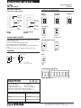
The designer dimmer that
matches your paddle switches.
PRODUCT FAMILY FEATURES
DIMENSIONS
Front Profile
SPECIFICATION SUBM ITTAL
CONTROLS AND ACCESSORIES
Preset
Fan-Speed
Switches
Dimmers
Controls
DELLORTNOC AERAEMAN BOJ
REBMUN BOJNOITACOL
.ON EGAPELTIT
SPECIFICATION SERIES
STANDARD FEATURES
• Square Law Dimming • RFI suppression
• Power-failure memory • Captive linear slider
• Electrostatic discharge tested • Precise color matching
• Mechanical air-gap switch to disconnect load power
Lutron controls are rated at 120 V~, 60 Hz unless otherwise noted.
Controls
Soft glow
nightlight
Select light
level with
slider
Switch on
to selected
light
level/off
Preset
Dimmer
Preset Fan-Speed
Controls
1.31 in
*
(33 mm)
2.75 in
(70 mm)
2.94 in
(75 mm)
4.69 in
(119 mm)
0.30 in (7.6 mm)
*
some models
up to 1.44 in (37 mm)
Select fan
speed with
slider
Switch on
to selected
fan
speed/off
Cable TV
Jack
Single
Telephone Jack
15 A
Receptacle
15 A
GFCI Receptacle
2-gang to 6-gang wallplates
Telephone/Cable TV Jacks
Standard Multigang Wallplates
Receptacles
Ports
6-Port
Frame
3691038c
Have questions or want to place an order?
Call Lutron Customer Assistance 1.844.LUTRON1 (588.7661)
www.lutron.com/diva
• Large paddle switch with a captive linear-slide dimmer for a standard
designer wallplate opening
• Full family of products for most lighting sources
• Dimmers frature built-in soft-glow nightlight
• Uses standard single-pole and 3-way wiring for easy installation in any
home
• For mor Diva choices, see the new Diva Satin Colors product line

2
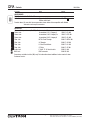
Maximum
Description Capacity
1,6
Model #
HI-POWER 2•4•6 DIMMING MODULES
To increase load capacity up to 30,000 W/VA in most popular
sources, use one DV-600P- or DV-603P- and add up to five
dimming modules. Cannot be used with 0−10 V - ballast.
FAN-SPEED CONTROLS
Quiet Controls
For use with one ceiling paddle fan.
Preset Fan-Speed Controls
3, 4
Single-pole/3-way, 1.5 A DVFSQ-F-
3-speed
SWITCHES
4
General Purpose Switching of all
Sources and Motor Loads
Single-pole,120/277 V 15 A CA-1PS-
3-way, 120/277 V 15 A CA-3PS-
4-way, 120/277 V 15 A CA-4PS-
ACCESSORIES
Receptacles
Receptacle
4
15 A125 V CAR-15-
GFCI Receptacle
4
15 A125 V CAR-15-GFCI-
Telephone and Cable Television Jacks
A physical barrier (partition) must exist when ganging with
line-voltage products
Single Telephone Jack
5
6-conductor, RJ11 CA-PJ-
Note: Also accepts most 4-conductor plugs.
Cable TV Jack
4, 5
F-
STYLE
75 Ω, coaxial cable jack CA-CJ-
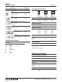
Maximum
Description Capacity
1,6
Model #
DIMMERS
Incandescent
Preset Dimmers with Nightlight
Single-pole 600 W DV-600P-
Single-pole 1000 W DV-10P-
3-way 600 W DV-603P-
3-way 1000 W DV-103P-
Note: The nightlight is visible best on the lighter colors. For
3-way and 4-way switching, use with Claro switches or other
mechanical switches.
Electronic Low-Voltage
Preset Dimmers with Nightlight
Single-pole 300 W DVELV-300P-
3-way 300 W DVELV-303P-
Note: Requires neutral wire connection. The nightlight is visible
best on the lighter colors. For 3-way and 4-way switching, use
with Claro switches or other mechanical switches.
Magnetic Low-Voltage
Preset Dimmers with Nightlight
Single-pole 600 VA (450 W
2
) DVLV-600P-
Single-pole 1000 VA (800 W
2
) DVLV-10P-
3-way 600 VA (450 W
2
) DVLV-603P-
3-way 1000 VA (800 W
2
) DVLV-103P-
Note: The nightlight is visible best on the lighter colors. For
3-way and 4-way switching, use with Claro switches or other
mechanical switches.
Fluorescent Dimming with Hi-lume and
Eco-10 (ECO-Series) Electronic Ballasts
Preset Dimmers with Nightlight
4
Single-pole/ 3-way 8 A DVF-103P-
Single-pole/ 3-way, 277 V~ 6 A DVF-103P-277-
Note: Use with Lutron Hi-lume or Eco-10 (ECO-Series) line
voltage control Electronic Dimming Ballasts only. Requires
neutral wire connection. The nightlight is visible best on the
lighter colors. For 3-way and 4-way switching, use with Claro
switches or other mechanical switches.
Preset Dimmers with Nightlight
Single-pole/ 3-way 5 A
Note: Use with Lutron Tu-Wire line voltage control electronic
dimming ballasts only. The nightlight is visible best on the
lighter colors. For 3-way and 4-way switching, use with Claro
switches or other mechanical switches.
1 For capacities in multigang installations see Derating/Maximum Capacity on pg.4
2 Actual lamp wattages.
3 For 3-way and 4-way switching, use with Claro switches or other mechanical switches.
4 No derating required if ganged.
5 A physical barrier (partition) must exist when ganging with line-voltage products.
Controls
Light Switch/ Fan-Speed Control
Single-pole switch:
DVFSQ-LF-
Fan 3-speed with off 1.5 A
Inc./
Hal. 2 A
CFL/
LED 1 A
Note: Does not have soft-glow nightlight.
4
3691038c
Have questions or want to place an order?
Call Lutron Customer Assistance 1.844.LUTRON1 (588.7661)
Fluorescent Dimming with Tu-Wire
Electronic Ballasts
DVFTU-5A3P-
6 For minimum load requirements see
Minimum Load Requirements on pg. 4

3
Controls
Model #RatingDescription
ACCESSORIES
Field Customizable Multi-Port Frame
-FP6-AC sknalb 6 htiw deppihSemarF troP-6
Shown with blanks
Product above: For use with Lutron connectors shown below. Also compatible with Hubble
Xcelerator and snap-fit connectors.
Connectors
For use with 6-port frame (CA-6PF-). Each connector fills one port.
HW-3C-P1-NOC3 yrogetaC,11JR,rotcudnoc-6kcaJ enohP
HW-E5C-P1-NOCe5 yrogetaC,54JR,rotcudnoc-8kcaJ enohP
HW-6C-P1-NOC6 yrogetaC,54JR,rotcudnoc-8kcaJ enohP
HW-JRTM-F1-NOC hguorhT-deeF JR-TM kcaJ rebiF
HW-CS-F1-NOCxelpmiS CS kcaJ rebiF
HW-CL-F1-NOCtnuoM hsulF-noN CL kcaJ rebiF
HW-TS-F1-NOCelytS TS kcaJ rebiF
HW-C1-NOCelbac laixaoC Ω57,elytS-FkcaJ elbaC
HW-B1-NOCrotcennoc CNBkcaJ CNB
Connectors available in white (WH) only. For information about additional colors contact Lutron
Customer Service.
3691038c
Have questions or want to place an order?
Call Lutron Customer Assistance 1.844.LUTRON1 (588.7661)

4
DERATING/MAXIMUM CAPACITY
No side One side Two side
sections section sections
removed removed removed
(Full Capacity) (End Units) (Middle Unit)
Incandescent Dimmers
600 W 500 W 400 W
1000 W 800 W 650 W
Electronic Low-Voltage
300 W 250 W 200 W
Magnetic Low-Voltage
600 VA 500 VA 400 VA
(450 W
1
) (375 W
1
) (300 W
1
)
1000 VA 800 VA 650 VA
(800 W
1
) (650 W
1
) (500 W
1
)
Fluorescent
Hi-lume/Eco-10
20 ballasts/ 8 A No derating required
(ECO-Series)
Tu-Wire
2
5 A 4 A 3.3 A
Fan-Speed Controls
1.5 A
No derating required
1 Actual lamp wattage.
2 Minimum capacity: 2 ballasts/0.25 A
# ledoMnoitpircseD
STANDARD WALLPLATES
1-Gang
2.94 in (75 mm) W x 4.69 in (119 mm) H x
0.30 in (7.6 mm) D
CW-1-
2-Gang
4.75 in (121 mm) W x 4.69 in (119 mm) H x
0.30 in (7.6 mm) D
CW-2-
3-Gang
6.56 in (167 mm) W x 4.69 in (119 mm) H x
0.30 in (7.6 mm) D
CW-3-
4-Gang
8.37 in (213 mm) W x 4.69 in (119 mm) H x
0.30 in (7.6 mm) D CW-4-
5-Gang
10.18 in (259 mm) W x 4.69 in (119 mm) H x
0.30 in (7.6 mm) D CW-5-
6-Gang
12.00 in (305 mm) W x 4.69in (119 mm) H x
0.30 in (7.6 mm) D
CW-6-
STANDARD COLORS/FINISHES
Gloss Finishes
Add color/finish suffix to model number to order.
Example: DV-600P-WH
WH White
IV Ivory
AL Almond
LA Light Almond
GR Gray
BR Brown
BL Black
Controls
3691038c
Have questions or want to place an order?
Call Lutron Customer Assistance 1.844.LUTRON1 (588.7661)
MINIMUM LOAD REQUIREMENTS
Incandescent/Magnetic Low-Voltage
40 W
Electronic Low-Voltage
5 W
Fan-Speed Controls
.33 A
(40 W)
Fluorescent
Hi-lume/Eco-10
1 ballast
(ECO-Series)
Tu-Wire
3
2 ballasts

5
Wiring Diagram 4
Model # 3-Way Wiring
DVELV-303P-
CA-3PS-
Wiring Diagram 5
3-Way Used as Single-Pole Model #
DVELV-303P-
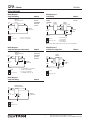
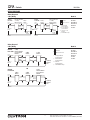
WIRING DIAGRAMS
Wiring Diagram 1
Single-Pole Wiring Model #
DV-600P-
DV-10P-
DVLV-600P-
DVLV-10P-
CA-1PS-
Wiring Diagram 2
Single-Pole Wiring of 3-Way Control Model #
DVFSQ-F-
DVLV-103P-
DVLV-603P-
DV-103P-
DV-603P-
Wiring Diagram 3
Single-Pole Wiring Model #
DVELV-300P-
Neutral
Black
*
Dimmer/
Switch/Fan-Speed
Control
Black or Red
*
Line/
Hot
120 V~
60 Hz
Lighting
Load or Fan
Green
**
** or Brass screw terminal
** or Green screw terminal
Ground
Wire Connectors
Control
Load Side
Neutral
Yellow
Line/
Hot
Green White
120 V~
60 Hz
*
Red
***
Lighting
Load
3-Way
Switch
3-Way
Dimmer
Neutral
Yellow
Line/
Hot
Green White
120 V~
60 Hz
Red
Red/
White
Lighting
Load
3-Way
Dimmer
Ground
Wire Connectors
***or Copper/Black
***screw terminal
***or Brass/Gold
***screw terminal
Ground
Wire Connectors
Green
***
Neutral
Black
*
Red
**
†
Red
**
Line/
Hot
120 V~
60 Hz
Lighting
Load or Fan
Ground
Wire Connectors
***or Copper/Black screw terminal
***or Brass screw terminal
***
or Green screw terminal
Dimmer/
Switch/Fan-Speed
Control
Red or Yellow
Green White
Neutral
Black
Dimmer/Switch/
Fan-Speed Control
Line/
Hot
120 V~
60 Hz
Lighting
Load or Fan
Ground
Wire Connectors
Controls
3691038c
Have questions or want to place an order?
Call Lutron Customer Assistance 1.844.LUTRON1 (588.7661)
†
or Red/White stripe (cap off)
Red/
White
Note: 3-way switch must be wired on the line side of the dimmer.

6
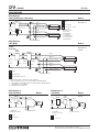
WIRING DIAGRAMS
Wiring Diagram 6
3-Way Wiring Model #
DV-603P-
DV-103P-
DVLV-603P-
DVLV-103P-
DVFSQ-F-
CA-3PS-
Wiring Diagram 7
4-Way Wiring Model #
DV-603P-
DV-103P-
DVLV-603P-
DVLV-103P-
DVFSQ-F-
CA-3PS-
CA-4PS-
Control
Line-Side
3-Way
Switch
Fan-Speed Control
or 3-Way
Dimmer/Switch
Fan-Speed Control
or 3-Way
Dimmer/Switch
Lighting
Load
or Fan
Neutral
Red
*
Red
*
†
Green
*********
Green
***
Black
**
Line/
Hot
120 V~
60 Hz
3-Way
Switch
Lighting
Load
or Fan
Neutral
Red
*
Red
*
†
Black
**
Line/
Hot
120 V~
60 Hz
OR
Control
Load-Side
Ground
Wire Connectors
*** **
*
*
*
***or Brass/Gold
***screw terminal
***or Copper/Black
***screw terminal
*** or Green screw
***terminal
†
or Red/White stripe
Control
Line-Side
Control
Load-Side
Black
**
Red
**
Red
*
†
*
*
*
** **
**
Red
*
†
*
Neutral
Line/
Hot
Green
** * ***
120 V~
60 Hz
3-Way
Dimmer/Switch
or Fan-Speed
Control
4-Way
Switch
Lighting
Load or
Fan
3-Way
Switch
Neutral
Line/
Hot
Green
***
120 V~
60 Hz
** *
*
*
**
**
Black
**
Red
*
4-Way
Switch
Lighting
Load or
Fan
3-Way
Switch
3-Way
Dimmer/Switch
or Fan-Speed
Control
OR
Ground
Wire Connectors
***or Copper/Black
***screw terminal
***or Brass/Gold
***screw terminal
***
or Green
***screw terminal
†
or Red/White stripe
Controls
3691038c
Have questions or want to place an order?
Call Lutron Customer Assistance 1.844.LUTRON1 (588.7661)

7
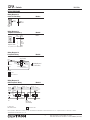
WIRING DIAGRAMS
Wiring Diagram 8
Model # Single-Pole Wiring of a 3-Way Control
DVF-103P-
DVF-103P-277-
Wiring Diagram 9
3-Way Wiring Model #
DVF-103P-
DVF-103P-277-
CA-3PS-
Green
120 V~
or
277 V~
60 Hz
To Additional Ballasts
Dimmer
Orange or Brown
**
White
*
BlackBlack
Orange or Brown
**
White
*
Yellow or Orange
Black
Blue Red
Line/
Hot
Neutral
White
Violet or Blue
*** must use lamp
***disconnect sockets
***with magnetic
***dimming ballasts
*** or Yellow/Blue or
***Yellow/Green when
***used with magnetic
***dimming ballasts
Dimming Ballast
Dimming Ballast
Ground
Wire Connectors
T
ypical 4-Wire Connection
Control
Load-Side
* 3-Way switch must be wired on line side of dimmer
**
*** or Yellow/Blue or Yellow/Green when used with magnetic dimming ballasts
† †
or Copper/Black screw terminal
††
or Brass/Gold screw terminal
GreenGreen
120 V~
or
277 V~
60 Hz
To Additional Ballasts
Dimmer
3-Way
Switch*
Orange or Brown
***
White
**
Black
Orange or Brown
***
White
**
Black
Red
Line/
Hot
Neutral
White
Violet
or Blue
Yellow or
Orange
Blue
†† †
†
Dimming Ballast
Dimming Ballast
Ground
Wire Connectors
Typical 4-Wire Connection
Controls
Wiring Diagram 10
Single-Pole Wiring Model #
DVFTU-5A3P-
Wiring Diagram 11
Model # 3-Way Wiring
DVTU-5A3P-
CA-3PS-
Black**Black
Green
To additional ballasts * or Red/White
** terminals are provided
Neutral
Red*
Red
Dimmer
Black
White**
Line/
Hot
120 V~
60 Hz
Tu-Wire
Ballast
Ground
Wire Connectors
Black**Black
To additional ballasts * or Red/White
** terminals are provided
White**
Green
Neutral
Red*
Red
Dimmer
3-way
Switch
Black
Line/
Hot
Green
120 V~
60 Hz
Ground
Wire Connectors
Tu-Wire
Ballast
3691038c
Have questions or want to place an order?
Call Lutron Customer Assistance 1.844.LUTRON1 (588.7661)
must use lamp disconnect sockets with magnetic dimming ballasts

8
WIRING DIAGRAMS
Wiring Diagram 12
Cable TV Jack Wiring Model #
CA-CJ-
Wiring Diagram 13
Telephone Jack Wirin g
Model #
CA-PJ-
Wiring Diagram 14
Model #Receptacle Wiring
CAR-15-
Wiring Diagram 15
GFCI Receptacle Wiring Model #
CAR-15-GFCI-
75 Ω
Cable
75 Ω
Cable
Cable TV
Jack
Ground
Neutral
Line/
Hot
Black
White
Green
or
Screw Terminal
Green
or
Screw Terminal
Green
or
Screw Terminal
Black
White
120 V~
60 Hz
GFCI
Receptacle
(15 A Shown)
NPNP PPPP
Line/
Hot
Load
Wire Connectors
P-Protected
NP-Not Protected
Lutron,
©2017-2018 Lutron Electronics Co., Inc.
)Lutron, Diva, Claro, Hi-lume, Eco-10, and Tu-Wire are trademarks of Lutron Electronics Co., Inc., registered in the U.S. and other countries.
Building Ground
(To Metal Box)
6-Conductor
Telephone Jack*
Wire
Color
Jack
Position
1
White
2
Black
3
Red
4
Green
5
Yellow
6
Blue
* accepts most 4-conductor jacks
Neutral
Black
Receptacle
(15 A Shown)
White
Line/
Hot
120 V~
60 Hz
Nickel
Plated
Screws
Brass
Screws
Green
Screw Ground or
Isolated Ground
Ground
Wire Connectors
Controls
3691038c
Have questions or want to place an order?
Call Lutron Customer Assistance 1.844.LUTRON1 (588.7661)
-
 1
1
-
 2
2
-
 3
3
-
 4
4
-
 5
5
-
 6
6
-
 7
7
-
 8
8


Powiązane artykuły
Inne dokumenty
-
Pyle PIWIPDK2 Instrukcja instalacji
-
Legrand Smart Tru-Universal Dimmer Instrukcja instalacji
-
Bticino F418U2IN Instrukcja obsługi
-
Eaton OS310R-C1-K instrukcja
-
-
-
Buchanan 30-1452J Instrukcja obsługi
-
Samsung SI-L8T23112CEU Skrócona instrukcja obsługi