Yamaha DM1000 Instrukcja obsługi
- Kategoria
- Dodatkowy sprzęt muzyczny
- Typ
- Instrukcja obsługi

Owner’s Manual
Owner’s Manual
Keep This Manual For Future Reference.
Keep This Manual For Future Reference.
E

FCC INFORMATION (U.S.A.)
1. IMPORTANT NOTICE: DO NOT MODIFY THIS UNIT! This product, when installed as indicated in the instructions contained in this manual, meets FCC
requirements. Modifications not expressly approved by Yamaha may void your authority, granted by the FCC, to use the product.
2. IMPORTANT: When connecting this product to accessories and/or another product use only high quality shielded cables. Cable/s supplied with this product MUST
be used. Follow all installation instructions. Failure to follow instructions could void your FCC authorization to use this product in the USA.
3. NOTE: This product has been tested and found to comply with the requirements listed in FCC Regulations, Part 15 for Class “B” digital devices. Compliance with
these requirements provides a reasonable level of assurance that your use of this product in a residential environment will not result in harmful interference with
other electronic devices. This equipment generates/uses radio frequencies and, if not installed and used according to the instructions found in the users manual, may
cause interference harmful to the operation of other electronic devices. Compliance with FCC regulations does not guarantee that interference will not occur in all
installations. If this product is found to be the source of interference, which can be determined by turning the unit “OFF” and “ON”, please try to eliminate the
problem by using one of the following measures: Relocate either this product or the device that is being affected by the interference. Utilize power outlets that are on
different branch (circuit breaker or fuse) circuits or install AC line filter/s. In the case of radio or TV interference, relocate/reorient the antenna. If the antenna lead-in
is 300 ohm ribbon lead, change the lead-in to coaxial type cable. If these corrective measures do not produce satisfactory results, please contact the local retailer
authorized to distribute this type of product. If you can not locate the appropriate retailer, please contact Yamaha Corporation of America, Electronic Service
Division, 6600 Orangethorpe Ave, Buena Park, CA 90620
The above statements apply ONLY to those products distributed by Yamaha Corporation of America or its subsidiaries.
ADVARSEL!
Lithiumbatteri—Eksplosionsfare ved fejlagtig
håndtering. Udskiftning må kun ske med batteri
af samme fabrikat og type. Levér det brugte
batteri tilbage til leverandoren.
VARNING
Explosionsfara vid felaktigt batteribyte. Använd
samma batterityp eller en ekvivalent typ som
rekommenderas av apparattillverkaren.
Kassera använt batteri enligt fabrikantens
instruktion.
VAROITUS
Paristo voi räjähtää, jos se on virheellisesti
asennettu. Vaihda paristo ainoastaan
laitevalmistajan suosittelemaan tyyppiin. Hävitä
käytetty paristo valmistajan ohjeiden
mukaisesti.
NEDERLAND THE NETHERLANDS
● Dit apparaat bevat een lithium batterij voor geheugen
back-up.
● Raadpleeg uw leverancier over de verwijdering van de
batterij op het moment dat u het apparaat ann het einde
van de levensduur afdankt of de volgende Yamaha Service
Afdeiing:
Yamaha Music Nederland Service Afdeiing
Kanaalweg 18-G, 3526 KL UTRECHT
Te l. 030-2828425
● Gooi de batterij niet weg, maar lever hem in als KCA.
● This apparatus contains a lithium battery for memory
back-up.
● For the removal of the battery at the moment of the
disposal at the end of the service life please consult your
retailer or Yamaha Service Center as follows:
Yamaha Music Nederland Service Center
Address: Kanaalweg 18-G, 3526 KL
UTRECHT
Te l: 030-2828425
● Do not throw away the battery. Instead, hand it in as small
chemical waste.
WARNING: THIS APPARATUS MUST BE EARTHED
IMPORTANT
THE WIRES IN THIS MAINS LEAD ARE COLOURED IN
ACCORDANCE WITH THE FOLLOWING CODE:
GREEN-AND-YELLOW : EARTH
BLUE : NEUTRAL
BROWN : LIVE
As the colours of the wires in the mains lead of this apparatus may
not correspond with the coloured markings identifying the terminals in
your plug, proceed as follows:
The wire which is coloured GREEN and YELLOW must be
connected to the terminal in the plug which is marked by the letter E
or by the safety earth symbol or coloured GREEN and YELLOW.
The wire which is coloured BLUE must be connected to the terminal
which is marked with the letter N or coloured BLACK.
The wire which is coloured BROWN must be connected to the
terminal which is marked with the letter L or coloured RED.
* This applies only to products distributed by YAMAHA KEMBLE
MUSIC (U.K.) LTD.

The above warning is located on the side
of the unit
• Explanation of Graphical Symbols
The lightning flash with arrowhead symbol
within an equilateral triangle is intended to
alert the user to the presence of uninsulated
“dangerous voltage” within the product’s
enclosure that may be of sufficient magnitude
to constitute a risk of electric shock to persons.
The exclamation point within an equilateral
triangle is intended to alert the user to the
presence of important operating and mainte-
nance (servicing) instructions in the literature
accompanying the product.
IMPORTANT SAFETY INSTRUCTIONS
1 Read these instructions.
2Keep these instructions.
3 Heed all warnings.
4 Follow all instructions.
5 Do not use this apparatus near water.
6 Clean only with dry cloth.
7 Do not block any ventilation openings. Install in
accordance with the manufacturer’s instruc-
tions.
8 Do not install near any heat sources such as
radiators, heat registers, stoves, or other appa-
ratus (including amplifiers) that produce heat.
9 Do not defeat the safety purpose of the polar-
ized or grounding-type plug. A polarized plug
has two blades with one wider than the other. A
grounding type plug has two blades and a third
grounding prong. The wide blade or the third
prong are provided for your safety. If the pro-
vided plug does not fit into your outlet, consult
an electrician for replacement of the obsolete
outlet.
10 Protect the power cord from being walked on or
pinched particularly at plugs, convenience
receptacles, and the point where they exit from
the apparatus.
11 Only use attachments/accessories specified by
the manufacturer.
12 Use only with the cart, stand,
tripod, bracket, or table spec-
ified by the manufacturer, or
sold with the apparatus.
When a cart is used, use cau-
tion when moving the cart/
apparatus combination to
avoid injury from tip-over.
13 Unplug this apparatus during lightning storms
or when unused for long periods of time.
14 Refer all servicing to qualified service person-
nel. Servicing is required when the apparatus
has been damaged in any way, such as power-
supply cord or plug is damaged, liquid has been
spilled or objects have fallen into the apparatus,
the apparatus has been exposed to rain or mois-
ture, does not operate normally, or has been
dropped.
CAUTION: TO REDUCE THE RISK OF
ELECTRIC SHOCK, DO NOT REMOVE
COVER (OR BACK). NO USER-SERVICEABLE
PARTS INSIDE. REFER SERVICING TO
QUALIFIED SERVICE PERSONNEL.
CAUTION
RISK OF ELECTRIC SHOCK
DO NOT OPEN
WARNING
TO REDUCE THE RISK OF FIRE OR ELECTRIC SHOCK,
DO NOT EXPOSE THIS APPARATUS TO RAIN OR MOISTURE.

4
Important Information
DM1000—Owner’s Manual
Important Information
Warnings
•Connect this unit’s power cord only to an AC outlet of the type stated in this Owner’s Man-
ual or as marked on the unit. Failure to do so is a fire and electrical shock hazard.
•Do not allow water to enter this unit or allow the unit to become wet. Fire or electrical shock
may result.
•Do not place heavy objects, including this unit, on top of the power cord. A damaged power
cord is a fire and electrical shock hazard. In particular, be careful not to place heavy objects
on a power cord covered by a carpet.
•Do not place a container with liquid or small metal objects on top of this unit. Liquid or
metal objects inside this unit are a fire and electrical shock hazard.
•Do not scratch, bend, twist, pull, or heat the power cord. A damaged power cord is a fire
and electrical shock hazard.
•Do not remove the unit’s cover. You could receive an electrical shock. If you think internal
inspection, maintenance, or repair is necessary, contact your dealer.
•Do not modify the unit. Doing so is a fire and electrical shock hazard.
•If lightning begins to occur, turn off the power switch of the unit as soon as possible, and
unplug the power cable plug from the electrical outlet.
•If there is a possibility of lightning, do not touch the power cable plug if it is still connected.
Doing so may be an electrical shock hazard.
•Use only the included power cord for this unit. Using other types may be a fire and electrical
shock hazard.
•This unit has rear-panel slots for installing mini-YGDAI cards. For technical reasons, cer-
tain card combinations are not supported. Before installing any cards, check the Yamaha
web site (see page 6) to see whether your card is compatible. Also check the total number of
cards that can be installed in the unit. Installing cards that are not endorsed by Yamaha may
cause electrical shock, fire, or damage to the unit.
•If the power cord is damaged (i.e., cut or a bare wire is exposed), ask your dealer for a
replacement. Using the unit with a damaged power cord is a fire and electrical shock hazard.
•If you notice any abnormality, such as smoke, odor, or noise, or if a foreign object or liquid
gets inside the unit, turn it off immediately. Remove the power cord from the AC outlet.
Consult your dealer for repair. Using the unit in this condition is a fire and electrical shock
hazard.
• Should this unit be dropped or the cabinet be damaged, turn the power switch off, remove
the power plug from the AC outlet, and contact your dealer. If you continue using the unit
without heeding this instruction, fire or electrical shock may result.
Cautions
•Keep this unit away from the following locations:
—Locations exposed to oil splashes or steam, such as near cooking stoves, humidifiers, etc.
—Unstable surfaces, such as a wobbly table or slope.
—Locations exposed to excessive heat, such as inside a car with all the windows closed, or
places that receive direct sunlight.
—Locations subject to excessive humidity or dust accumulation.
•Hold the power cord plug when disconnecting it from an AC outlet. Never pull the cord. A
damaged power cord is a potential fire and electrical shock hazard.
•Do not touch the power plug with wet hands. Doing so is a potential electrical shock hazard.

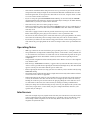
Operating Notes
5
DM1000—Owner’s Manual
•This unit has ventilation holes along the front, rear, top, and sides to prevent the internal
temperature from rising too high. Do not block them. Blocked ventilation holes are a fire
hazard. In particular, do not operate the unit while it’s on its side, is upside down, or while
it’s covered with a cloth or dust sheet.
•If you are using the optional MB1000 Peak Meter Bridge, do not hold only the MB1000
when moving this unit. Otherwise, the meter brackets may be damaged, the main unit may
malfunction, or you may be injured if the unit falls.
•This unit is heavy. Use two or more people to carry it.
•When you transport or move this unit with the MB1000 attached, do not permit impact or
stress on the cable connector that connects the MB1000 to this unit. Otherwise, malfunc-
tion may occur.
•This unit is equipped with a dedicated ground connection to prevent electrical shock.
Before connecting the power plug to an AC outlet, be sure to ground the unit.
•To relocate the unit, turn the power switch off, remove the power plug from the AC outlet,
and remove all connecting cables. Damaged cables may cause fire or electrical shock.
•If you know you will not use this unit for a long period of time, such as when going on vaca-
tion, remove the power plug from the AC outlet. Leaving it connected is a potential fire haz-
ard.
Operating Notes
• XLR-type connectors are wired as follows: pin 1–ground, pin 2–hot (+), and pin 3–cold (–).
•The performance of components with moving contacts, such switches, rotary controls, fad-
ers, and connectors, deteriorates over time. The rate of deterioration depends on the oper-
ating environment and is unavoidable. Consult your dealer about replacing defective
components.
•Using a mobile telephone near this unit may induce noise. If noise occurs, use the telephone
away from the unit.
•If the message “WARNING Low Battery!” appears when you turn on this unit, contact your
dealer as soon as possible about replacing the internal data backup battery. The unit will still
operate correctly, but data other than the presets will be lost.
•Before replacing the batteries, back up your data to a memory card, or another unit by using
MIDI Bulk Dump.
•The digital circuits of this unit may induce a slight noise into nearby radios and TVs. If noise
occurs, relocate the affected equipment.
•When connecting D-sub cables, be sure to tighten the screws on both sides of the connector
securely. To disconnect the cable, loosen the screws completely, then remove the cable by
holding the connector part. Do not remove the plug by pulling the cable while the screws
are still attached. Otherwise, the connector may be damaged, leading to malfunction.
•When you change the wordclock settings on any device in your digital audio system, some
devices may output noise, so turn down your power amps beforehand, otherwise your
speakers may be damaged.
Interference
This unit uses high-frequency digital circuits that may cause interference on radio and tele-
vision equipment located nearby. If interference is a problem, relocate the affected equip-
ment. Using a mobile telephone near the unit may induce noise. In this case use the
telephone away from the unit.

6
Important Information
DM1000—Owner’s Manual
Exclusion of Certain Responsibility
Manufacturer, importer, or dealer shall not be liable for any incidental damages including
personal injury or any other damages caused by improper use or operation of this unit.
Trademarks
ADAT MultiChannel Optical Digital Interface is a trademark and ADAT and Alesis are reg-
istered trademarks of Alesis Corporation. Apogee is a trademark of Apogee Electronics, Inc.
Apple, Mac, and Power Macintosh are registered trademarks and Mac OS is a trademark of
Apple Corporation, Inc. HUI is a trademark of Mackie Designs, Inc. Intel and Pentium are
registered trademarks of Intel Corporation. Nuendo is a registered trademark of Steinberg
Media Technologies AG. Pro Tools is a trademark or registered trademark of Digidesign
and/or Avid Technology, Inc. Tascam Digital Interface is a trademark and Tascam and Teac
are registered trademarks of Teac Corporation. Microsoft and Windows are registered
trademarks of Microsoft Corporation, Inc. Waves is a trademark of Waves, Inc. Yamaha is a
trademark of Yamaha Corporation. All other trademarks are the property of their respective
holders and are hereby acknowledged.
Copyright
No part of this unit, its software, or this
Owner’s Manual
may be reproduced or distributed
in any form or by any means without the prior written authorization of Yamaha Corpora-
tion.
© 2003 Yamaha Corporation. All rights reserved.
Yamaha Web Site
Further information about this unit, related products, and other Yamaha professional audio
equipment is available on the Yamaha Professional Audio Web site at:
<http://www.yamahaproaudio.com/>.
Package Contents
• DM1000 Digital Production Console
• CD-ROM
•Power cord
•This manual
•Studio Manager Installation Guide
Optional Extras
• MB1000 Peak Meter Bridge
• SP1000 Wooden Side Panels
• RK1 Rack Mount Kit
• mini YGDAI I/O cards

About this Owner’s Manual
7
DM1000—Owner’s Manual
About this Owner’s Manual
This
Owner’s Manual
explains how to operate the DM1000 Digital Production Console.
The table of contents can help you familiarize yourself with the manual’s organization and
to locate tasks and topics The index can help you locate specific information.
Before diving in, it’s recommend that you read the “Operating Basics” chapter, starting on
page 27.
Each chapter in this manual discusses a specific section or function of the DM1000. The
Input and Output Channels are explained in the following chapters: “Input Channels,” “Bus
Outs,” and “Aux Sends.” Where possible, these chapters have been organized in order of sig-
nal flow, from input to output.
Conventions Used in this Manual
The DM1000 features two types of buttons: physical buttons that you can press (e.g.,
ENTER and DISPLAY) and buttons that appear on the display pages. References to physical
buttons are enclosed in square brackets, for example, “press the [ENTER] button.” Refer-
ences to display page buttons are not emphasized, for example, “move the cursor to the ON
button.”
You can select display pages by using the [DISPLAY] buttons or the Left Tab Scroll, Right
Tab Scroll, and F1–4 buttons below the display. In order to simplify explanations, the pro-
cedures reference only the [DISPLAY] button method. See “Selecting Display Pages” on
page 28 for details on all the ways in which pages can be selected.
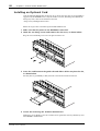
Installing the DM1000
The DM1000 should be placed on a strong and stable surface, in a location that complies
with the warnings and cautions listed in the previous sections.
Always turn the power off when the instrument is not in use.
The illustrations and LCD screens as shown in this owner’s manual are for instructional
purposes only, and may appear somewhat different from those on your instrument.
Copying of commercially available music sequence data and/or digital audio files is
strictly prohibited except for your personal use.

8
Contents
DM1000—Owner’s Manual
Contents
1 Welcome . . . . . . . . . . . . . . . . . . . . . . . . . . . . . . . . . . . . . . . . . . . . 11
2 Control Surface & Rear Panel . . . . . . . . . . . . . . . . . . . . . . . . . . . . 13
Control Surface . . . . . . . . . . . . . . . . . . . . . . . . . . . . . . . . . . . . . . . . . . . . . . . . . . . . . 13
Rear Panel . . . . . . . . . . . . . . . . . . . . . . . . . . . . . . . . . . . . . . . . . . . . . . . . . . . . . . . . . . . . . 23
Installing an Optional Card . . . . . . . . . . . . . . . . . . . . . . . . . . . . . . . . . . . . . . . . . . . . . . 26
3 Operating Basics . . . . . . . . . . . . . . . . . . . . . . . . . . . . . . . . . . . . . . 27
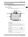
About the Display . . . . . . . . . . . . . . . . . . . . . . . . . . . . . . . . . . . . . . . . . . . . . . . . . . . 27
Selecting Display Pages . . . . . . . . . . . . . . . . . . . . . . . . . . . . . . . . . . . . . . . . . . . . . . . 28
Display Interface . . . . . . . . . . . . . . . . . . . . . . . . . . . . . . . . . . . . . . . . . . . . . . . . . . . . 29
Selecting Layers . . . . . . . . . . . . . . . . . . . . . . . . . . . . . . . . . . . . . . . . . . . . . . . . . . . . . . . . 31
Selecting Channels . . . . . . . . . . . . . . . . . . . . . . . . . . . . . . . . . . . . . . . . . . . . . . . . . . 32
Selecting Fader Modes . . . . . . . . . . . . . . . . . . . . . . . . . . . . . . . . . . . . . . . . . . . . . . . . . . . 33
Selecting Encoder Modes . . . . . . . . . . . . . . . . . . . . . . . . . . . . . . . . . . . . . . . . . . . . . . . . 34
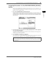
Assigning Parameters to the ENCODER MODE [ASSIGN] button . . . . . . . . . . . . . . 35
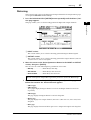
Metering . . . . . . . . . . . . . . . . . . . . . . . . . . . . . . . . . . . . . . . . . . . . . . . . . . . . . . . . . . . . . . 37
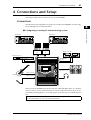
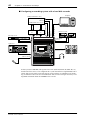
4 Connections and Setup . . . . . . . . . . . . . . . . . . . . . . . . . . . . . . . . . 41
Connections . . . . . . . . . . . . . . . . . . . . . . . . . . . . . . . . . . . . . . . . . . . . . . . . . . . . . . . 41
Wordclock Connections and Settings . . . . . . . . . . . . . . . . . . . . . . . . . . . . . . . . . . . . . . 44
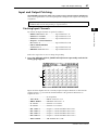
Input and Output Patching . . . . . . . . . . . . . . . . . . . . . . . . . . . . . . . . . . . . . . . . . . . . . . . 47
5 Analog I/O & Digital I/O . . . . . . . . . . . . . . . . . . . . . . . . . . . . . . . . 51
Analog Inputs & Outputs . . . . . . . . . . . . . . . . . . . . . . . . . . . . . . . . . . . . . . . . . . . . . 51
Digital Inputs & Outputs . . . . . . . . . . . . . . . . . . . . . . . . . . . . . . . . . . . . . . . . . . . . . 52
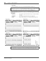
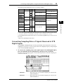
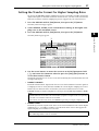
Converting Sampling Rates of Signals Received at 2TR Digital Inputs . . . . . . . . 53
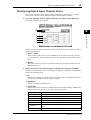
Monitoring Digital Input Channel Status . . . . . . . . . . . . . . . . . . . . . . . . . . . . . . . . . . . 55
Dithering Digital Outputs . . . . . . . . . . . . . . . . . . . . . . . . . . . . . . . . . . . . . . . . . . . . 56
Setting the Transfer Format for Higher Sampling Rates . . . . . . . . . . . . . . . . . . . . . . . 57
6 Input Channels . . . . . . . . . . . . . . . . . . . . . . . . . . . . . . . . . . . . . . . 59
About Input Channels . . . . . . . . . . . . . . . . . . . . . . . . . . . . . . . . . . . . . . . . . . . . . . . 59
Setting the Input Channels from the Display . . . . . . . . . . . . . . . . . . . . . . . . . . . . . 60
Setting the Input Channels from the Control Surface . . . . . . . . . . . . . . . . . . . . . . 71
Pairing Input Channels . . . . . . . . . . . . . . . . . . . . . . . . . . . . . . . . . . . . . . . . . . . . . . . . . . 73
Naming Input Channels . . . . . . . . . . . . . . . . . . . . . . . . . . . . . . . . . . . . . . . . . . . . . . . . . 76
Using MS Stereo Microphone . . . . . . . . . . . . . . . . . . . . . . . . . . . . . . . . . . . . . . . . . . . . 77
7 Bus Outs . . . . . . . . . . . . . . . . . . . . . . . . . . . . . . . . . . . . . . . . . . . . 79
About Stereo Out . . . . . . . . . . . . . . . . . . . . . . . . . . . . . . . . . . . . . . . . . . . . . . . . . . . 79
Bus Out 1–8 . . . . . . . . . . . . . . . . . . . . . . . . . . . . . . . . . . . . . . . . . . . . . . . . . . . . . . . . 80
Setting the Stereo Out and Bus Out 1–8 from the Display . . . . . . . . . . . . . . . . . . . . . 81
Setting the Stereo Out and Bus Out 1–8 from the Control Surface . . . . . . . . . . . . . . 86
Pairing Buses or Aux Sends . . . . . . . . . . . . . . . . . . . . . . . . . . . . . . . . . . . . . . . . . . . . . . . 87
Attenuating Output Signals . . . . . . . . . . . . . . . . . . . . . . . . . . . . . . . . . . . . . . . . . . . . . . 88
Naming the Stereo Out and Bus Outs . . . . . . . . . . . . . . . . . . . . . . . . . . . . . . . . . . . . . . 89
8 Aux Sends . . . . . . . . . . . . . . . . . . . . . . . . . . . . . . . . . . . . . . . . . . . 91
Aux Out 1–8 . . . . . . . . . . . . . . . . . . . . . . . . . . . . . . . . . . . . . . . . . . . . . . . . . . . . . . . 91
Setting Aux Out 1–8 from the Control Surface . . . . . . . . . . . . . . . . . . . . . . . . . . . . . . . 92
Setting Aux Out 1–8 from the Display . . . . . . . . . . . . . . . . . . . . . . . . . . . . . . . . . . 92
Setting Aux Send Levels . . . . . . . . . . . . . . . . . . . . . . . . . . . . . . . . . . . . . . . . . . . . . . . . . . 96
Viewing Aux Send Settings for Multiple Channels . . . . . . . . . . . . . . . . . . . . . . . . . . . . 100
Panning Aux Sends . . . . . . . . . . . . . . . . . . . . . . . . . . . . . . . . . . . . . . . . . . . . . . . . . . . . . 102
Excluding Certain Channels from Aux Sends (Mix Minus) . . . . . . . . . . . . . . . . . 103
Copying Channel Fader Positions to Aux Sends . . . . . . . . . . . . . . . . . . . . . . . . . . . . . . 104

Contents
9
DM1000—Owner’s Manual
9 Input & Output Patching . . . . . . . . . . . . . . . . . . . . . . . . . . . . . . . 105
Input Patching . . . . . . . . . . . . . . . . . . . . . . . . . . . . . . . . . . . . . . . . . . . . . . . . . . . . . . 105
Output Patching . . . . . . . . . . . . . . . . . . . . . . . . . . . . . . . . . . . . . . . . . . . . . . . . . . . . . . . . 108
Patching Direct Outs . . . . . . . . . . . . . . . . . . . . . . . . . . . . . . . . . . . . . . . . . . . . . . . . . . . . 111
Insert Patching . . . . . . . . . . . . . . . . . . . . . . . . . . . . . . . . . . . . . . . . . . . . . . . . . . . . . . 112
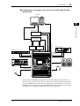
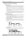
10 Control Room Monitoring . . . . . . . . . . . . . . . . . . . . . . . . . . . . . . 115
Control Room Monitor . . . . . . . . . . . . . . . . . . . . . . . . . . . . . . . . . . . . . . . . . . . . . . 115
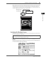
Control Room Monitor and Solo Setup . . . . . . . . . . . . . . . . . . . . . . . . . . . . . . . . . 116
Using the Control Room Monitor . . . . . . . . . . . . . . . . . . . . . . . . . . . . . . . . . . . . . . . . . 118
Using the Solo Function . . . . . . . . . . . . . . . . . . . . . . . . . . . . . . . . . . . . . . . . . . . . . . 118
Using the Talkback Function . . . . . . . . . . . . . . . . . . . . . . . . . . . . . . . . . . . . . . . . . . 119
11 Surround Functions . . . . . . . . . . . . . . . . . . . . . . . . . . . . . . . . . . . 121
Using Surround Pan . . . . . . . . . . . . . . . . . . . . . . . . . . . . . . . . . . . . . . . . . . . . . . . . . 121
Surround Monitoring . . . . . . . . . . . . . . . . . . . . . . . . . . . . . . . . . . . . . . . . . . . . . . . . 131
12 Grouping Channels & Linking Parameters . . . . . . . . . . . . . . . . . . 141
Grouping & Linking . . . . . . . . . . . . . . . . . . . . . . . . . . . . . . . . . . . . . . . . . . . . . . . . . 141
Using Fader Groups and Mute Groups . . . . . . . . . . . . . . . . . . . . . . . . . . . . . . . . . . . . . 142
Linking EQ and Compressor Parameters . . . . . . . . . . . . . . . . . . . . . . . . . . . . . . . . 144
13 Internal Effects . . . . . . . . . . . . . . . . . . . . . . . . . . . . . . . . . . . . . . . 147
About the Internal Effects . . . . . . . . . . . . . . . . . . . . . . . . . . . . . . . . . . . . . . . . . . . . . 147
Using Effects Processors via Aux Sends . . . . . . . . . . . . . . . . . . . . . . . . . . . . . . . . . . . . . 148
Inserting the Internal Effects into Channels . . . . . . . . . . . . . . . . . . . . . . . . . . . . . . . . . 150
Editing Effects . . . . . . . . . . . . . . . . . . . . . . . . . . . . . . . . . . . . . . . . . . . . . . . . . . . . . . . . . 151
About Surround Effects . . . . . . . . . . . . . . . . . . . . . . . . . . . . . . . . . . . . . . . . . . . . . . . . . . 153
About Plug-Ins . . . . . . . . . . . . . . . . . . . . . . . . . . . . . . . . . . . . . . . . . . . . . . . . . . . . . 153
14 Scene Memories . . . . . . . . . . . . . . . . . . . . . . . . . . . . . . . . . . . . . . 155
About Scene Memories . . . . . . . . . . . . . . . . . . . . . . . . . . . . . . . . . . . . . . . . . . . . . . . 155
Storing and Recalling Scenes . . . . . . . . . . . . . . . . . . . . . . . . . . . . . . . . . . . . . . . . . . . . . 157
Auto Scene Memory Update . . . . . . . . . . . . . . . . . . . . . . . . . . . . . . . . . . . . . . . . . . 159
Fading Scenes . . . . . . . . . . . . . . . . . . . . . . . . . . . . . . . . . . . . . . . . . . . . . . . . . . . . . . . . . . 160
Recalling Scenes Safely . . . . . . . . . . . . . . . . . . . . . . . . . . . . . . . . . . . . . . . . . . . . . . . . . . 162
Sorting Scenes . . . . . . . . . . . . . . . . . . . . . . . . . . . . . . . . . . . . . . . . . . . . . . . . . . . . . . . . . 163
15 Libraries . . . . . . . . . . . . . . . . . . . . . . . . . . . . . . . . . . . . . . . . . . . . 165
About the Libraries . . . . . . . . . . . . . . . . . . . . . . . . . . . . . . . . . . . . . . . . . . . . . . . . . . 165
General Library Operation . . . . . . . . . . . . . . . . . . . . . . . . . . . . . . . . . . . . . . . . . . . . 165
Using Libraries . . . . . . . . . . . . . . . . . . . . . . . . . . . . . . . . . . . . . . . . . . . . . . . . . . . . . . . . . 167
16 Automix . . . . . . . . . . . . . . . . . . . . . . . . . . . . . . . . . . . . . . . . . . . . 181
About Automix . . . . . . . . . . . . . . . . . . . . . . . . . . . . . . . . . . . . . . . . . . . . . . . . . . . . . 181
Setting Up for Automix Recording . . . . . . . . . . . . . . . . . . . . . . . . . . . . . . . . . . . . . . . . 182
Recording an Automix . . . . . . . . . . . . . . . . . . . . . . . . . . . . . . . . . . . . . . . . . . . . . . . . . . 184
Punching In & Out . . . . . . . . . . . . . . . . . . . . . . . . . . . . . . . . . . . . . . . . . . . . . . . . . . . . . 188
[SEL] Button Functions While the [AUTO] Button Indicator Is On . . . . . . . . . . . . . 190
Playing Back an Automix . . . . . . . . . . . . . . . . . . . . . . . . . . . . . . . . . . . . . . . . . . . . . 190
Automix Main Page . . . . . . . . . . . . . . . . . . . . . . . . . . . . . . . . . . . . . . . . . . . . . . . . . . . . . 191
Automix Memory Page . . . . . . . . . . . . . . . . . . . . . . . . . . . . . . . . . . . . . . . . . . . . . . . 195
Fader1 &2 pages . . . . . . . . . . . . . . . . . . . . . . . . . . . . . . . . . . . . . . . . . . . . . . . . . . . . . 196
Editing Events Offline . . . . . . . . . . . . . . . . . . . . . . . . . . . . . . . . . . . . . . . . . . . . . . . . . . . 198
17 Remote Control . . . . . . . . . . . . . . . . . . . . . . . . . . . . . . . . . . . . . . 205
About Remote Function . . . . . . . . . . . . . . . . . . . . . . . . . . . . . . . . . . . . . . . . . . . . . . 205
Pro Tools Remote Layer . . . . . . . . . . . . . . . . . . . . . . . . . . . . . . . . . . . . . . . . . . . . . . 206
Nuendo Remote Layer . . . . . . . . . . . . . . . . . . . . . . . . . . . . . . . . . . . . . . . . . . . . . . . . . . . 224
Other DAW Remote Layers . . . . . . . . . . . . . . . . . . . . . . . . . . . . . . . . . . . . . . . . . . . 224
MIDI Remote Layer . . . . . . . . . . . . . . . . . . . . . . . . . . . . . . . . . . . . . . . . . . . . . . . . . . . . . 225
Machine Control Function . . . . . . . . . . . . . . . . . . . . . . . . . . . . . . . . . . . . . . . . . . . . 231

10
Contents
DM1000—Owner’s Manual
18 MIDI . . . . . . . . . . . . . . . . . . . . . . . . . . . . . . . . . . . . . . . . . . . . . . . . 235
MIDI & the DM1000 . . . . . . . . . . . . . . . . . . . . . . . . . . . . . . . . . . . . . . . . . . . . . . . . 235
MIDI Port Setup . . . . . . . . . . . . . . . . . . . . . . . . . . . . . . . . . . . . . . . . . . . . . . . . . . . . 236
Assigning Scenes to Program Changes for Remote Recall . . . . . . . . . . . . . . . . . . 239
Assigning Parameters to Control Changes for Real-time Control . . . . . . . . . . . . 240
Controlling Parameters by Using Parameter Changes . . . . . . . . . . . . . . . . . . . . . . . . . 246
Transmitting Parameter Settings via MIDI (Bulk Dump) . . . . . . . . . . . . . . . . . . 246
19 Other Functions . . . . . . . . . . . . . . . . . . . . . . . . . . . . . . . . . . . . . . . 249
Changing the Input and Output Connector Names . . . . . . . . . . . . . . . . . . . . . . . 249
Setting Preferences . . . . . . . . . . . . . . . . . . . . . . . . . . . . . . . . . . . . . . . . . . . . . . . . . . 250
Creating a Custom Layer by Combining Channels (User Assignable Layer) . . . . . . . 255
Using the Oscillator . . . . . . . . . . . . . . . . . . . . . . . . . . . . . . . . . . . . . . . . . . . . . . . . . . . . . 256
Using the User Defined Keys . . . . . . . . . . . . . . . . . . . . . . . . . . . . . . . . . . . . . . . . . . 257
Using GPI (General Purpose Interface) . . . . . . . . . . . . . . . . . . . . . . . . . . . . . . . . . . . . . 259
Using Operation Lock . . . . . . . . . . . . . . . . . . . . . . . . . . . . . . . . . . . . . . . . . . . . . . . . . . . 263
Cascading Consoles . . . . . . . . . . . . . . . . . . . . . . . . . . . . . . . . . . . . . . . . . . . . . . . . . . . . . 265
Using the AD824 . . . . . . . . . . . . . . . . . . . . . . . . . . . . . . . . . . . . . . . . . . . . . . . . . . . . . . . 270
Checking the Battery and the System Version . . . . . . . . . . . . . . . . . . . . . . . . . . . . . . . 272
Initializing the DM1000 . . . . . . . . . . . . . . . . . . . . . . . . . . . . . . . . . . . . . . . . . . . . . . . . . 273
Calibrating the Faders . . . . . . . . . . . . . . . . . . . . . . . . . . . . . . . . . . . . . . . . . . . . . . . . . . . 274
Appendix A: Parameter Lists . . . . . . . . . . . . . . . . . . . . . . . . . . . . . . . . 275
USER DEFINED KEYS . . . . . . . . . . . . . . . . . . . . . . . . . . . . . . . . . . . . . . . . . . . . . . . 275
USER DEFINED KEYS Initial Assignments . . . . . . . . . . . . . . . . . . . . . . . . . . . . . . . . . 277
Input Patch Parameters . . . . . . . . . . . . . . . . . . . . . . . . . . . . . . . . . . . . . . . . . . . . . . . . . . 278
Initial Input Patch Settings . . . . . . . . . . . . . . . . . . . . . . . . . . . . . . . . . . . . . . . . . . . . . . . 280
Output Patch Parameters . . . . . . . . . . . . . . . . . . . . . . . . . . . . . . . . . . . . . . . . . . . . . . . . 282
Initial Output Patch Settings . . . . . . . . . . . . . . . . . . . . . . . . . . . . . . . . . . . . . . . . . . 284
GPI Trigger Source List . . . . . . . . . . . . . . . . . . . . . . . . . . . . . . . . . . . . . . . . . . . . . . . . . . 286
User Defined Remote Layer Initial Bank Settings . . . . . . . . . . . . . . . . . . . . . . . . . . . . . 287
Effects Parameters . . . . . . . . . . . . . . . . . . . . . . . . . . . . . . . . . . . . . . . . . . . . . . . . . . . 291
Preset EQ Parameters . . . . . . . . . . . . . . . . . . . . . . . . . . . . . . . . . . . . . . . . . . . . . . . . . . . 316
Preset Gate Parameters (fs = 44.1 kHz) . . . . . . . . . . . . . . . . . . . . . . . . . . . . . . . . . . . . . 320
Preset Compressor Parameters (fs = 44.1 kHz) . . . . . . . . . . . . . . . . . . . . . . . . . . . 320
Appendix B: Specifications . . . . . . . . . . . . . . . . . . . . . . . . . . . . . . . . . . 325
General Spec . . . . . . . . . . . . . . . . . . . . . . . . . . . . . . . . . . . . . . . . . . . . . . . . . . . . . . . 325
Libraries . . . . . . . . . . . . . . . . . . . . . . . . . . . . . . . . . . . . . . . . . . . . . . . . . . . . . . . . . . . . . . 330
Analog Input Spec . . . . . . . . . . . . . . . . . . . . . . . . . . . . . . . . . . . . . . . . . . . . . . . . . . . 330
Analog Output Spec . . . . . . . . . . . . . . . . . . . . . . . . . . . . . . . . . . . . . . . . . . . . . . . . . 330
Digital Input Spec . . . . . . . . . . . . . . . . . . . . . . . . . . . . . . . . . . . . . . . . . . . . . . . . . . . 331
Digital Output Spec . . . . . . . . . . . . . . . . . . . . . . . . . . . . . . . . . . . . . . . . . . . . . . . . . 331
I/O Slot Spec (1–2) . . . . . . . . . . . . . . . . . . . . . . . . . . . . . . . . . . . . . . . . . . . . . . . . . . . . . . 332
Control I/O Spec . . . . . . . . . . . . . . . . . . . . . . . . . . . . . . . . . . . . . . . . . . . . . . . . . . . . 332
REMOTE Port . . . . . . . . . . . . . . . . . . . . . . . . . . . . . . . . . . . . . . . . . . . . . . . . . . . . . . . . . 333
CONTROL Port . . . . . . . . . . . . . . . . . . . . . . . . . . . . . . . . . . . . . . . . . . . . . . . . . . . . 333
Dimensions . . . . . . . . . . . . . . . . . . . . . . . . . . . . . . . . . . . . . . . . . . . . . . . . . . . . . . . . . . . . 334
Appendix C: MIDI . . . . . . . . . . . . . . . . . . . . . . . . . . . . . . . . . . . . . . . . . 336
Scene Memory to Program Change Table . . . . . . . . . . . . . . . . . . . . . . . . . . . . . . . 336
Initial Parameter to Control Change Table . . . . . . . . . . . . . . . . . . . . . . . . . . . . . . . . . . 337
MIDI Data Format . . . . . . . . . . . . . . . . . . . . . . . . . . . . . . . . . . . . . . . . . . . . . . . . . . . . . . 353
Appendix D: About Optional Product . . . . . . . . . . . . . . . . . . . . . . . . . 368
MB1000 Peak Meter Bridge . . . . . . . . . . . . . . . . . . . . . . . . . . . . . . . . . . . . . . . . . . . 368
Installing the SP1000 Side Panels . . . . . . . . . . . . . . . . . . . . . . . . . . . . . . . . . . . . . . . . . . 371
Rack Mounting the DM1000 Using the RK1 Rack Mount Kit . . . . . . . . . . . . . . . 371
Index . . . . . . . . . . . . . . . . . . . . . . . . . . . . . . . . . . . . . . . . . . . . . . . . . . . 372

Welcome
11
DM1000—Owner’s Manual
1
Welcome
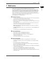
1 Welcome
Thank you for choosing the Yamaha DM1000 Digital Production Console.
The compact DM1000 Digital Console features 24-bit/96 kHz digital audio processing
without compromise, as well as 48-channel simultaneous mixing. The DM1000 covers a
broad range of needs and applications, including multi-track recording, 2-channel mix-
down, and cutting-edge surround sound production. This integrated, comprehensive
audio system features remote control function for DAWs (Digital Audio Workstations) as
popularized by the DM2000 and 02R96 Digital Mixing Consoles.
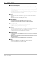
The DM1000 offers the following features:
■
Hardware Features
• 17 touch-sensitive 100-mm motorized faders (for touch-sensitive selection of channels,
or for punching in and out during Automix recording)
•Faders can set levels for Input Channels, Aux Sends, and Bus Outs.
•Rotary Encoders enable you to control panning for each channel, AUX send levels, and
various parameters.
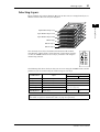
•Six selectable software layers determine the function of channel faders and Encoders.
• 320 x 240 dot LCD display with fluorescent backlighting
•Buttons and controls in the SELECTED CHANNEL section enable direct editing of
channel mix parameters.
• 12 USER-DEFINED KEYS enable you to assign functions to control DM1000 internal
parameters.
•Two expansion slots for optional digital I/O, AD, and DA cards.
■
Sonic Specifications
• Linear 24-bit, 128-times oversampling A/D converters
• Linear 24-bit, 128-times oversampling D/A converters
• 20 Hz through 40 kHz frequency response at 96 kHz sampling rate.
• 106 dB typical dynamic range
• 32-bit internal signal processing (58-bit accumulator)
■
Inputs and Outputs
• 16 mic/line inputs with switchable +48 V phantom power and 4 line inputs
• 12 Omni Outs assignable to Stereo Out, Bus Out, Monitor Out, and Input Channel
Direct Outs.
•Two optional slots allow a maximum of 32 inputs.
•Two 2-track digital inputs, with sampling rate converters capable of converting sam-
pling rates of 44.1 kHz through 96 kHz.
•Double Channel support for recording and playing at 88.2/96 kHz on 44.1/48 kHz leg-
acy multi-track digital recorders.
•You can cascade two DM1000s while remaining in the digital domain.
•Input patches enable assignment of input signals to desired signal paths.
•Output patches enable assignment of Bus Out signals and Input Channel Direct Outs to
desired output jacks.

12
Chapter 1—Welcome
DM1000—Owner’s Manual
■
Channel Configuration
•Simultaneous mixing of up to 48 Input Channels. Group multiple channels and pair
channels for stereo.
•8 Bus Outs and 8 AUX Sends. Buses 1-8 can be routed to Stereo Buses for use as Group
Buses.
•Channel library for storing and recalling the channel settings for each Input Channel
and Output Channel.
• 4-band EQ and dynamics processor equip all channels. Dynamics processor and EQ set-
tings can be stored in libraries and recalled.
■
Effects
•Four high-quality multi-channel effects (Apply effects via AUX Sends or Channel
Inserts).
• Effect library for storing and recalling effect settings.
■
Scene Memory
•Scene memories for storing and recalling the mix settings as Scenes.
•Snapshot style automation with Scene memories recallable via Automix.
■ Surround Sound
•Supports 3-1, 5.1, and 6.1 channel surround sound production.
•Joystick for adjusting each channel's surround pan.
■ Automix
•Automated controls of channel faders and parameters via Automix. (Even more power-
ful when combined with an MTR, DAW, and MIDI sequence system.)
•Control parameters of connected MIDI devices via Automix.
■ Remote Control
•Control and manage your DM1000 from your Mac or PC using bundled Studio Man-
ager software
•Remote Layers for controlling popular DAWs (Digital Audio Workstations), including
Pro Tools, Nuendo, etc.
•Control an external recorder via MMC commands and P2 commands.
■ MIDI
•Equipped with MIDI ports and a USB port for computer connection.
•Scene recall and mix parameter changes via MIDI

Control Surface & Rear Panel 13
DM1000—Owner’s Manual
2
Control Surface & Rear Panel
2 Control Surface & Rear Panel
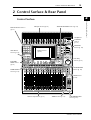
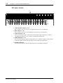
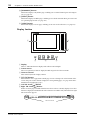
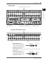
Control Surface
AUXPAN
DISPLAY
ASSIGN
ENCODER MODE
EQUALIZER
LOW
HIGH
GAIN
Q
FREQUENCY
LOW MID
HIGH MID
ROUTING
12
34
56
78
STEREO DIRECT
DISPLAY
DISPLAY
SELECTED CHANNEL
16
BUS 8
32 48
15
BUS 7
31 47
14
BUS 6
30 46
13
BUS 5
29 45
12
BUS 4
28 44
11
BUS 3
27 43
10
16151413121110
20dB
ONOFF
+48V
1
2
3
4
5
6
78 1213
14
15
16
91011
1615141312111098765432
PEAK
SIGNAL
1
-16
-60
GAIN
-16
-60
GAIN
-16
-60
GAIN
-16
-60
GAIN
-16
-60
GAIN
-16
-60
GAIN
-16
-60
GAIN
-16
-60
GAIN
-16
-60
GAIN
-16
-60
GAIN
-16
-60
GAIN
-16
-60
GAIN
-16
-60
GAIN
-16
-60
GAIN
-16
-60
GAIN
-16
-60
GAIN
PEAK
SIGNAL
PEAK
SIGNAL
PEAK
SIGNAL
PEAK
SIGNAL
PEAK
SIGNAL
PEAK
SIGNAL
PEAK
SIGNAL
PEAK
SIGNAL
PEAK
SIGNAL
PEAK
SIGNAL
PEAK
SIGNAL
PEAK
SIGNAL
PEAK
SIGNAL
PEAK
SIGNAL
PEAK
SIGNAL
PAD
20dB 20dB 20dB 20dB 20dB 20dB 20dB 20dB 20dB 20dB 20dB 20dB 20dB 20dB 20dB
ONOFF
+48V
ONOFF
+48V
ONOFF
+48V
ONOFF
+48V
ONOFF
+48V
ONOFF
+48V
ONOFF
+48V
ONOFF
+48V
ONOFF
+48V
ONOFF
+48V
ONOFF
+48V
ONOFF
+48V
ONOFF
+48V
ONOFF
+48V
ONOFF
+48V
0
5
10
15
20
30
40
50
60
70
50
40
30
20
15
10
+10
5
0
5
ON
SOLO
SEL
AUX 1
1
1
17 33
0
5
10
15
20
30
40
50
60
70
50
40
30
20
15
10
+10
5
0
5
ON
SOLO
SEL
AUX 2
2
2
18 34
0
5
10
15
20
30
40
50
60
70
50
40
30
20
15
10
+10
5
0
5
ON
SOLO
SEL
AUX 3
3
3
19 35
0
5
10
15
20
30
40
50
60
70
50
40
30
20
15
10
+10
5
0
5
ON
SOLO
SEL
AUX 4
4
4
20 36
0
5
10
15
20
30
40
50
60
70
50
40
30
20
15
10
+10
5
0
5
ON
SOLO
SEL
AUX 5
5
5
21 37
0
5
10
15
20
30
40
50
60
70
50
40
30
20
15
10
+10
5
0
5
ON
SOLO
SEL
AUX 6
6
6
22 38
0
5
10
15
20
30
40
50
60
70
50
40
30
20
15
10
+10
5
0
5
ON
SOLO
SEL
AUX 7
7
7
23 39
0
5
10
15
20
30
40
50
60
70
50
40
30
20
15
10
+10
5
0
5
ON
SOLO
SEL
AUX 8
8
8
24 40
0
5
10
15
20
30
40
50
60
70
50
40
30
20
15
10
+10
5
0
5
ON
SOLO
SEL
BUS 1
9
9
25 41
0
5
10
15
20
30
40
50
60
70
50
40
30
20
15
10
+10
5
0
5
ON
SOLO
SEL
0
5
10
15
20
30
40
50
60
70
50
40
30
20
15
10
+10
5
0
5
0
5
10
15
20
30
40
50
60
70
50
40
30
20
15
10
+10
5
0
5
0
5
10
15
20
30
40
50
60
70
50
40
30
20
15
10
+10
5
0
5
0
5
10
15
20
30
40
50
60
70
50
40
30
20
15
10
+10
5
0
5
0
5
10
15
20
30
40
50
60
70
50
40
30
20
15
10
+10
5
0
5
0
5
10
15
20
30
40
50
60
70
50
40
30
20
15
10
+10
5
0
5
ON
SOLO
SEL
ON
SOLO
SEL
ON
SOLO
SEL
ON
SOLO
SEL
ON
SOLO
SEL
ON
SOLO
SEL
BUS 2
26 42
AUTO
ON
SEL
STEREO
70
60
50
40
30
20
15
10
5
0
AUX2 AUX3 AUX4
AUX6AU X5 AUX7 AU X8
AUX SELECT
DISPLAY
FADER MODE
FADER
AUX
DISPLAY ACCESS
AUTOMIX DIO SETUP UTILITY
MIDI REMOTE METER VIEW
PAI R /GROUP
INPUT
OUTPUT
EFFECTSURROUND DYNAMICS SCENE
/
PAN/
INSERT/DELAY
PATCH
PATC H
GRAB
SCENE MEMORY
STORERECALL
DISPLAY
USER DEFINED
KEYS
ENTER
INC
DEC
TAL KB ACK LEVEL
PHONES
LEVEL
010
010
PHONES
MONITOR
LEVEL
SOLO CLEAR
2TR D1
2TR D2
DIMMER
TALKBACK
MONITOR
STEREO
SLOT
BUS
DISPLAY
100
F1 F2 F3
F4
0
OVER
-2
-4
-6
-8
-10
-12
-14
-18
-24
-30
-36
-42
-48
-56
-72
0
OVER
-2
-4
-6
-8
-10
-12
-14
-18
-24
-30
-36
-42
-48
-56
-72
LR
AD Input Section (p. 14) SELECTED CHANNEL Section (p. 19)
Headphones
& Talkback
Section
(p. 21)
MONITOR
Section (p. 22)
Channel Strip Section (p. 15) STEREO Section (p. 15) USER DEFINED KEYS
Section (p. 21)
Data Entry
Section (p. 21)
LAYER Section
(p. 20)
SCENE MEMORY
Section (p. 20)
Display Section
(p. 18)
DISPLAY ACCESS Section
(p. 17)
AUX SELECT
Section (p. 16)
ENCODER
MODE Section
(p. 16)
FADER MODE
Section (p. 16)

14 Chapter 2—Control Surface & Rear Panel
DM1000—Owner’s Manual
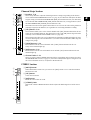
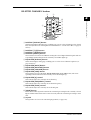
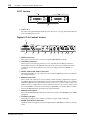
AD Input Section
A +48V ON/OFF switches 1–16
These switches turn on or off the +48 V phantom power feed to each INPUT.
B PAD switches 1–16
These switches turn on or off the 20 dB pad (attenuator) for each AD Input.
C GAIN controls 1–16
These controls adjust input sensitivity for each AD Input. Input sensitivity is +4 dB to
–40 dB when the Pad is on, and –16 dB to –60 dB when the Pad is off.
D PEAK indicators 1–16
These indicators light up when the input signal level is 3 dB below clipping. Adjust the Pad
switch and GAIN control so that the indicator rarely lights up at signal peak.
E SIGNAL indicators
These indicators light up when the input signal level is 20 dB below nominal.
20dB
ONOFF
+48V
1
2
3
4
5
6
78 1213
14
15
16
91011
1615141312111098765432
PEAK
SIGNAL
1
-16
-60
GAIN
-16
-60
GAIN
-16
-60
GAIN
-16
-60
GAIN
-16
-60
GAIN
-16
-60
GAIN
-16
-60
GAIN
-16
-60
GAIN
-16
-60
GAIN
-16
-60
GAIN
-16
-60
GAIN
-16
-60
GAIN
-16
-60
GAIN
-16
-60
GAIN
-16
-60
GAIN
-16
-60
GAIN
PEAK
SIGNAL
PEAK
SIGNAL
PEAK
SIGNAL
PEAK
SIGNAL
PEAK
SIGNAL
PEAK
SIGNAL
PEAK
SIGNAL
PEAK
SIGNAL
PEAK
SIGNAL
PEAK
SIGNAL
PEAK
SIGNAL
PEAK
SIGNAL
PEAK
SIGNAL
PEAK
SIGNAL
PEAK
SIGNAL
PAD
20dB 20dB 20dB 20dB 20dB 20dB 20dB 20dB 20dB 20dB 20dB 20dB 20dB 20dB 20dB
ONOFF
+48V
ONOFF
+48V
ONOFF
+48V
ONOFF
+48V
ONOFF
+48V
ONOFF
+48V
ONOFF
+48V
ONOFF
+48V
ONOFF
+48V
ONOFF
+48V
ONOFF
+48V
ONOFF
+48V
ONOFF
+48V
ONOFF
+48V
ONOFF
+48V
2
3
4
5
1

Control Surface 15
DM1000—Owner’s Manual
2
Control Surface & Rear Panel
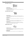
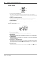
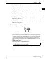
Channel Strip Section
A Encoders 1–16
These rotary Encoders adjust the channel parameter settings. Depending on the button
selected in the ENCODER MODE section (see page 16), the Encoders will adjust the chan-
nel pan setting (when the ENCODER MODE [PAN] button indicator is lit), the AUX Send
level (when the ENCODER MODE [AUX] button indicator is lit), or any parameter (when
the ENCODER MODE [ASSIGN] button indicator is lit).
These Encoders also feature push switches that are used to view the value of the parameter
currently assigned to the Encoder, or to punch in or out during Automix recording.
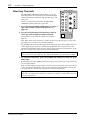
B [SEL] buttons 1–16
These buttons enable you to select desired channels. The [SEL] button indicator for the cur-
rently-selected channel lights up. The channel selected by each [SEL] button depends on the
currently-selected button in the LAYER section (see page 20).
These buttons also allow you to select channels for Automix recording and playback, create
or cancel channel pairs, and add channels to (or remove them from) Fader, Mute, EQ, and
Compressor groups.
C [SOLO] buttons 1–16
These buttons solo the selected channels. The [SOLO] button indicator of the cur-
rently-soloed channel lights up.
D [ON] buttons 1–16
These buttons turn the selected channels on or off. The [ON] button indicators for On
channels light up.
E Channel faders 1–16
These are touch-sensitive 100 mm motorized faders. Depending on the button selected in
the FADER MODE Section (see page 16), the faders will adjust the input or output level of
the selected channels or buses, or adjust the AUX Send level.
STEREO Section
A [AUTO] button
When this button is turned on, you can use the [SEL] buttons 1–16 to turn the Automix
function on or off.
B [SEL] button
Selects the Stereo Bus.
C [ON] button
Turns the selected bus on or off.
D [STEREO] fader
This touch-sensitive 100 mm motorized fader adjusts the final output level of the Stereo
Bus.
0
5
10
15
20
30
40
50
60
70
50
40
30
20
15
10
+10
5
0
5
ON
SOLO
SEL
AUX 1
1
1
17 33
1
2
3
4
5
AUTO
ON
SEL
STEREO
70
60
50
40
30
20
15
10
5
0
1
2
3
4

16 Chapter 2—Control Surface & Rear Panel
DM1000—Owner’s Manual
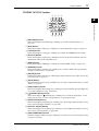
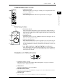
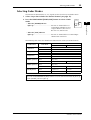
AUX SELECT Section
A [DISPLAY] button
This button displays an Aux-related page (see page 97).
B [AUX 1]–[AUX 8] buttons
These buttons select an Aux Send. When you press a button to select an AUX Send, the cor-
responding button indicator lights up.
ENCODER MODE Section
A [DISPLAY] button
This button displays an Encoder page, enabling you to assign functions to Encoders 1–16
(see page 35). To use a function assigned to an Encoder, press the [ASSIGN] button to turn
on the button indicator.
B [PAN] button
If you press this button, the button indicator turns on and Encoders 1–16 function as chan-
nel panpots.
C [AUX] button
If you press this button, the button indicator turns on and Encoders 1–16 function as chan-
nel Aux Send. The Send destination is selected in the AUX SELECT Section.
D [ASSIGN] button
If you press this button, the button indicator turns on and Encoders 1–16 function as
assignable controls for the parameters assigned on the Encoder pages. (By default, Input
Patches of the corresponding Input Channels are assigned.)
FADER MODE Section
A [FADER/AUX] button
Toggles between the desired parameter to be adjusted by channel faders 1–16. The faders
adjust the Channel or Bus level when the FADER indicator is lit, and adjust the Aux Send
level when the AUX indicator is lit.
B FADER indicator
C AUX indicator
An indicator lights up to indicate the parameter selected via the [FADER/AUX] button.
AUX2 AUX3 AUX4
AUX6AUX5 AUX7 AUX8
AUX SELECT
DISPLAY
AUX1
1
2
AUXPAN
DISPLAY
ASSIGN
ENCODER MODE
1
2 3 4
FADER MODE
FADE R
AUX
1
2
3

Control Surface 17
DM1000—Owner’s Manual
2
Control Surface & Rear Panel
DISPLAY ACCESS Section
A [AUTOMIX] button
This button displays an Automix page, enabling you to make Automix settings (see
page 181).
B [DIO] button
This button displays a DIO page, enabling you to make digital I/O settings (see page 53).
C [SETUP] button
This button displays a Setup page, enabling you to make the DM1000 internal settings.
D [UTILITY] button
This button displays a Utility page, enabling you to use the internal oscillators and view
information about installed optional cards.
E [MIDI] button
This button displays a MIDI page, enabling you to make MIDI settings (see page 238).
F [REMOTE] button
This button displays a Remote page, enabling you to control a DAW remotely and make
machine control settings (see page 205).
G [METER] button
This button displays a Meter page, which displays Input Channel levels, or Bus Out or Aux
Send Out levels (see page 37).
H [VIEW] button
This button displays a View page, enabling you to view and set mix parameters for a specific
channel (see page 69).
I [PAIR/GROUP] button
This button displays a Pair/Group page, enabling you to pair channels, group multiple fad-
ers, or mute channels (see page 74 and 141).
J [ /INSERT/DELAY] button
This button displays a /INS/DLY page, enabling you to switch the signal phase, set the
signal to be inserted, or set the delay parameters (see page 60 and 150).
K [INPUT PATCH] button
This button displays an In Patch page, enabling you to patch input signals and Bus Out sig-
nals to the desired Input Channels (see page 105).
L [OUTPUT PATCH] button
This button displays an Out Patch page, enabling you to patch Bus Out and Insert Out sig-
nals to the desired destination (see page 108).
M [PAN/SURROUND] button
This button displays a Pan/Surr page, enabling you to adjust stereo or surround pan settings
(see page 67 and 121).
DISPLAY ACCESS
AUTOMIX DIO SETUP UTILITY
MIDI REMOTE METER VIEW
PAIR/GROUP
INPUT
OUTPUT
EFFECTSURROUND DYNAMICS SCENE
/
PA N/
INSERT/DELAY
PAT CH
PATCH
1 2 3
M
N O P
J
4
K
9
L
5
6
8
7

18 Chapter 2—Control Surface & Rear Panel
DM1000—Owner’s Manual
N [DYNAMICS] button
This button displays a Dynamics page, enabling you to control channel gates and compres-
sors (see page 62).
O [EFFECT] button
This button displays an Effect page, enabling you to edit the internal effects processors and
use optional plug-in cards (see page 151).
P [SCENE] button
This button displays a Scene page, enabling you to store and recall Scenes (see page 155).
Display Section
A Display
This is a 320 x 240 dot LCD display with a fluorescent backlight.
B Stereo meters
These 32-segment level meters display the final output level of the Stereo Bus.
C Contrast control
This control adjusts the display contrast.
D [F1]–[F4] buttons
These buttons select a page from a multi-page screen. Selecting a tab at the bottom of the
screen using one of these buttons displays the corresponding page. (See page 28 for more
information on displaying a page.)
E Left Tab Scroll [ ] button
F Right Tab Scroll [ ] button
If there are more pages available than the four whose tabs are currently displayed, use these
buttons to display the additional tabs. These buttons are available only when the left or right
Tab Scroll arrow appears.
F1 F2 F3
F4
0
OVER
-2
-4
-6
-8
-10
-12
-14
-18
-24
-30
-36
-42
-48
-56
-72
0
OVER
-2
-4
-6
-8
-10
-12
-14
-18
-24
-30
-36
-42
-48
-56
-72
LR
2
3
45 6
1
Tab Scroll arrow

Control Surface 19
DM1000—Owner’s Manual
2
Control Surface & Rear Panel
SELECTED CHANNEL Section
A ROUTING [DISPLAY] button
This button displays a Routing page, enabling you to route selected channels to the desired
Bus, and adjust the level of the signals routed from Buses 1–8 to the Stereo Bus (see page 68
and 83).
B ROUTING [1]–[8] buttons
C ROUTING [STEREO] button
D ROUTING [DIRECT] button
These buttons select the desired Bus for routing the selected Input Channel signals. The cor-
responding button indicator for the currently-selected Bus lights up.
E EQUALIZER [DISPLAY] button
This button displays an EQ page, enabling you to set the selected channel equalizer (see
page 64 and 65).
F EQUALIZER [HIGH] button
G EQUALIZER [HIGH-MID] button
H EQUALIZER [LOW-MID] button
I EQUALIZER [LOW] button
These buttons select the EQ band (HIGH, HIGH-MID, LOW-MID, LOW). The corre-
sponding button indicator of the currently-selected band lights up.
J EQUALIZER [Q] control
This control adjusts the currently-selected band Q.
K EQUALIZER [FREQUENCY] control
This control adjusts the currently-selected band frequency.
L EQUALIZER [GAIN] control
This control adjusts the currently-selected band gain.
M [GRAB] button
This button enables Joystick control of the surround pan setting for the currently-selected
Input Channel. This button can be turned on only when the surround pan setting is avail-
able.
N Joystick
The Joystick is used to set the surround pan position (see page 126).
EQUALIZER
LOW
HIGH
GAIN
Q
FREQUENCY
LOW MID
HIGH MID
ROUTING
12
34
56
78
STEREO DIRECT
DISPLAY
DISPLAY
SELECTED CHANNEL
GRAB
2
1 5
6
J
7
8
9
K
MN
3
L
4

20 Chapter 2—Control Surface & Rear Panel
DM1000—Owner’s Manual
LAYER Section
A [1-16]/[17-32]/[33-48] buttons
These buttons select an Input Channel Layer. The channel strips control Channels 1–16,
17–32, or 33–48, depending on the button selected here. (See page 31 for more information
on Layers.)
B [REMOTE 1]/[REMOTE 2] buttons
These buttons select the Remote Layer, which can be used to control external devices,
including DAWs. (See page 205 for more information on the Remote Layer.)
C [MASTER] button
This button selects the Master Layer, which can be used to control Bus and Aux Send. (See
page 31 for more information on the Master Layer.)
SCENE MEMORY Section
A Scene memory display
The number of the currently-selected Scene memory is displayed here.
B Edit indicator
If you adjust a mix parameter after a Scene has been recalled or stored, a dot flashes here.
C [STORE] button
This button enables you to store the current mix settings (See page 155 for more informa-
tion on Scene Memories).
D Scene Up [ ] / Down [ ] buttons
These buttons select a Scene to store or recall. Pressing the Scene Up [ ] button increments
the selection; pressing the Scene Down [ ] button decrements the selection. Holding down
either key increments or decrements the selection continuously.
E [RECALL] button
This button recalls the Scene memory selected by the Scene Up [ ] / Down [ ] buttons.
1
3
2
SCENE MEMORY
STORERECALL
21 3 4 5
Strona jest ładowana ...
Strona jest ładowana ...
Strona jest ładowana ...
Strona jest ładowana ...
Strona jest ładowana ...
Strona jest ładowana ...
Strona jest ładowana ...
Strona jest ładowana ...
Strona jest ładowana ...
Strona jest ładowana ...
Strona jest ładowana ...
Strona jest ładowana ...
Strona jest ładowana ...
Strona jest ładowana ...
Strona jest ładowana ...
Strona jest ładowana ...
Strona jest ładowana ...
Strona jest ładowana ...
Strona jest ładowana ...
Strona jest ładowana ...
Strona jest ładowana ...
Strona jest ładowana ...
Strona jest ładowana ...
Strona jest ładowana ...
Strona jest ładowana ...
Strona jest ładowana ...
Strona jest ładowana ...
Strona jest ładowana ...
Strona jest ładowana ...
Strona jest ładowana ...
Strona jest ładowana ...
Strona jest ładowana ...
Strona jest ładowana ...
Strona jest ładowana ...
Strona jest ładowana ...
Strona jest ładowana ...
Strona jest ładowana ...
Strona jest ładowana ...
Strona jest ładowana ...
Strona jest ładowana ...
Strona jest ładowana ...
Strona jest ładowana ...
Strona jest ładowana ...
Strona jest ładowana ...
Strona jest ładowana ...
Strona jest ładowana ...
Strona jest ładowana ...
Strona jest ładowana ...
Strona jest ładowana ...
Strona jest ładowana ...
Strona jest ładowana ...
Strona jest ładowana ...
Strona jest ładowana ...
Strona jest ładowana ...
Strona jest ładowana ...
Strona jest ładowana ...
Strona jest ładowana ...
Strona jest ładowana ...
Strona jest ładowana ...
Strona jest ładowana ...
Strona jest ładowana ...
Strona jest ładowana ...
Strona jest ładowana ...
Strona jest ładowana ...
Strona jest ładowana ...
Strona jest ładowana ...
Strona jest ładowana ...
Strona jest ładowana ...
Strona jest ładowana ...
Strona jest ładowana ...
Strona jest ładowana ...
Strona jest ładowana ...
Strona jest ładowana ...
Strona jest ładowana ...
Strona jest ładowana ...
Strona jest ładowana ...
Strona jest ładowana ...
Strona jest ładowana ...
Strona jest ładowana ...
Strona jest ładowana ...
Strona jest ładowana ...
Strona jest ładowana ...
Strona jest ładowana ...
Strona jest ładowana ...
Strona jest ładowana ...
Strona jest ładowana ...
Strona jest ładowana ...
Strona jest ładowana ...
Strona jest ładowana ...
Strona jest ładowana ...
Strona jest ładowana ...
Strona jest ładowana ...
Strona jest ładowana ...
Strona jest ładowana ...
Strona jest ładowana ...
Strona jest ładowana ...
Strona jest ładowana ...
Strona jest ładowana ...
Strona jest ładowana ...
Strona jest ładowana ...
Strona jest ładowana ...
Strona jest ładowana ...
Strona jest ładowana ...
Strona jest ładowana ...
Strona jest ładowana ...
Strona jest ładowana ...
Strona jest ładowana ...
Strona jest ładowana ...
Strona jest ładowana ...
Strona jest ładowana ...
Strona jest ładowana ...
Strona jest ładowana ...
Strona jest ładowana ...
Strona jest ładowana ...
Strona jest ładowana ...
Strona jest ładowana ...
Strona jest ładowana ...
Strona jest ładowana ...
Strona jest ładowana ...
Strona jest ładowana ...
Strona jest ładowana ...
Strona jest ładowana ...
Strona jest ładowana ...
Strona jest ładowana ...
Strona jest ładowana ...
Strona jest ładowana ...
Strona jest ładowana ...
Strona jest ładowana ...
Strona jest ładowana ...
Strona jest ładowana ...
Strona jest ładowana ...
Strona jest ładowana ...
Strona jest ładowana ...
Strona jest ładowana ...
Strona jest ładowana ...
Strona jest ładowana ...
Strona jest ładowana ...
Strona jest ładowana ...
Strona jest ładowana ...
Strona jest ładowana ...
Strona jest ładowana ...
Strona jest ładowana ...
Strona jest ładowana ...
Strona jest ładowana ...
Strona jest ładowana ...
Strona jest ładowana ...
Strona jest ładowana ...
Strona jest ładowana ...
Strona jest ładowana ...
Strona jest ładowana ...
Strona jest ładowana ...
Strona jest ładowana ...
Strona jest ładowana ...
Strona jest ładowana ...
Strona jest ładowana ...
Strona jest ładowana ...
Strona jest ładowana ...
Strona jest ładowana ...
Strona jest ładowana ...
Strona jest ładowana ...
Strona jest ładowana ...
Strona jest ładowana ...
Strona jest ładowana ...
Strona jest ładowana ...
Strona jest ładowana ...
Strona jest ładowana ...
Strona jest ładowana ...
Strona jest ładowana ...
Strona jest ładowana ...
Strona jest ładowana ...
Strona jest ładowana ...
Strona jest ładowana ...
Strona jest ładowana ...
Strona jest ładowana ...
Strona jest ładowana ...
Strona jest ładowana ...
Strona jest ładowana ...
Strona jest ładowana ...
Strona jest ładowana ...
Strona jest ładowana ...
Strona jest ładowana ...
Strona jest ładowana ...
Strona jest ładowana ...
Strona jest ładowana ...
Strona jest ładowana ...
Strona jest ładowana ...
Strona jest ładowana ...
Strona jest ładowana ...
Strona jest ładowana ...
Strona jest ładowana ...
Strona jest ładowana ...
Strona jest ładowana ...
Strona jest ładowana ...
Strona jest ładowana ...
Strona jest ładowana ...
Strona jest ładowana ...
Strona jest ładowana ...
Strona jest ładowana ...
Strona jest ładowana ...
Strona jest ładowana ...
Strona jest ładowana ...
Strona jest ładowana ...
Strona jest ładowana ...
Strona jest ładowana ...
Strona jest ładowana ...
Strona jest ładowana ...
Strona jest ładowana ...
Strona jest ładowana ...
Strona jest ładowana ...
Strona jest ładowana ...
Strona jest ładowana ...
Strona jest ładowana ...
Strona jest ładowana ...
Strona jest ładowana ...
Strona jest ładowana ...
Strona jest ładowana ...
Strona jest ładowana ...
Strona jest ładowana ...
Strona jest ładowana ...
Strona jest ładowana ...
Strona jest ładowana ...
Strona jest ładowana ...
Strona jest ładowana ...
Strona jest ładowana ...
Strona jest ładowana ...
Strona jest ładowana ...
Strona jest ładowana ...
Strona jest ładowana ...
Strona jest ładowana ...
Strona jest ładowana ...
Strona jest ładowana ...
Strona jest ładowana ...
Strona jest ładowana ...
Strona jest ładowana ...
Strona jest ładowana ...
Strona jest ładowana ...
Strona jest ładowana ...
Strona jest ładowana ...
Strona jest ładowana ...
Strona jest ładowana ...
Strona jest ładowana ...
Strona jest ładowana ...
Strona jest ładowana ...
Strona jest ładowana ...
Strona jest ładowana ...
Strona jest ładowana ...
Strona jest ładowana ...
Strona jest ładowana ...
Strona jest ładowana ...
Strona jest ładowana ...
Strona jest ładowana ...
Strona jest ładowana ...
Strona jest ładowana ...
Strona jest ładowana ...
Strona jest ładowana ...
Strona jest ładowana ...
Strona jest ładowana ...
Strona jest ładowana ...
Strona jest ładowana ...
Strona jest ładowana ...
Strona jest ładowana ...
Strona jest ładowana ...
Strona jest ładowana ...
Strona jest ładowana ...
Strona jest ładowana ...
Strona jest ładowana ...
Strona jest ładowana ...
Strona jest ładowana ...
Strona jest ładowana ...
Strona jest ładowana ...
Strona jest ładowana ...
Strona jest ładowana ...
Strona jest ładowana ...
Strona jest ładowana ...
Strona jest ładowana ...
Strona jest ładowana ...
Strona jest ładowana ...
Strona jest ładowana ...
Strona jest ładowana ...
Strona jest ładowana ...
Strona jest ładowana ...
Strona jest ładowana ...
Strona jest ładowana ...
Strona jest ładowana ...
Strona jest ładowana ...
Strona jest ładowana ...
Strona jest ładowana ...
Strona jest ładowana ...
Strona jest ładowana ...
Strona jest ładowana ...
Strona jest ładowana ...
Strona jest ładowana ...
Strona jest ładowana ...
Strona jest ładowana ...
Strona jest ładowana ...
Strona jest ładowana ...
Strona jest ładowana ...
Strona jest ładowana ...
Strona jest ładowana ...
Strona jest ładowana ...
Strona jest ładowana ...
Strona jest ładowana ...
Strona jest ładowana ...
Strona jest ładowana ...
Strona jest ładowana ...
Strona jest ładowana ...
Strona jest ładowana ...
Strona jest ładowana ...
Strona jest ładowana ...
Strona jest ładowana ...
Strona jest ładowana ...
Strona jest ładowana ...
Strona jest ładowana ...
Strona jest ładowana ...
Strona jest ładowana ...
Strona jest ładowana ...
Strona jest ładowana ...
Strona jest ładowana ...
Strona jest ładowana ...
Strona jest ładowana ...
Strona jest ładowana ...
Strona jest ładowana ...
Strona jest ładowana ...
Strona jest ładowana ...
Strona jest ładowana ...
Strona jest ładowana ...
Strona jest ładowana ...
Strona jest ładowana ...
Strona jest ładowana ...
Strona jest ładowana ...
Strona jest ładowana ...
Strona jest ładowana ...
Strona jest ładowana ...
Strona jest ładowana ...
Strona jest ładowana ...
Strona jest ładowana ...
Strona jest ładowana ...
Strona jest ładowana ...
Strona jest ładowana ...
Strona jest ładowana ...
Strona jest ładowana ...
Strona jest ładowana ...
Strona jest ładowana ...
Strona jest ładowana ...
Strona jest ładowana ...
Strona jest ładowana ...
Strona jest ładowana ...
Strona jest ładowana ...
Strona jest ładowana ...
Strona jest ładowana ...
Strona jest ładowana ...
Strona jest ładowana ...
Strona jest ładowana ...
Strona jest ładowana ...
Strona jest ładowana ...
Strona jest ładowana ...
Strona jest ładowana ...
Strona jest ładowana ...
Strona jest ładowana ...
Strona jest ładowana ...
Strona jest ładowana ...
Strona jest ładowana ...
-
 1
1
-
 2
2
-
 3
3
-
 4
4
-
 5
5
-
 6
6
-
 7
7
-
 8
8
-
 9
9
-
 10
10
-
 11
11
-
 12
12
-
 13
13
-
 14
14
-
 15
15
-
 16
16
-
 17
17
-
 18
18
-
 19
19
-
 20
20
-
 21
21
-
 22
22
-
 23
23
-
 24
24
-
 25
25
-
 26
26
-
 27
27
-
 28
28
-
 29
29
-
 30
30
-
 31
31
-
 32
32
-
 33
33
-
 34
34
-
 35
35
-
 36
36
-
 37
37
-
 38
38
-
 39
39
-
 40
40
-
 41
41
-
 42
42
-
 43
43
-
 44
44
-
 45
45
-
 46
46
-
 47
47
-
 48
48
-
 49
49
-
 50
50
-
 51
51
-
 52
52
-
 53
53
-
 54
54
-
 55
55
-
 56
56
-
 57
57
-
 58
58
-
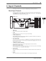 59
59
-
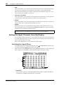 60
60
-
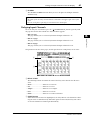 61
61
-
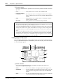 62
62
-
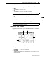 63
63
-
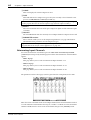 64
64
-
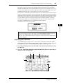 65
65
-
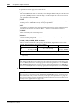 66
66
-
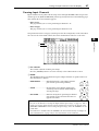 67
67
-
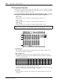 68
68
-
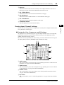 69
69
-
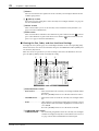 70
70
-
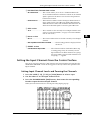 71
71
-
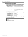 72
72
-
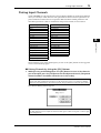 73
73
-
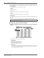 74
74
-
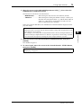 75
75
-
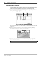 76
76
-
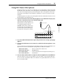 77
77
-
 78
78
-
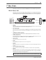 79
79
-
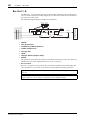 80
80
-
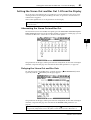 81
81
-
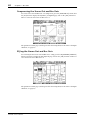 82
82
-
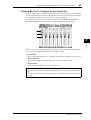 83
83
-
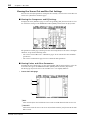 84
84
-
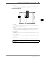 85
85
-
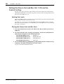 86
86
-
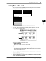 87
87
-
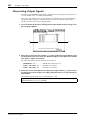 88
88
-
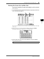 89
89
-
 90
90
-
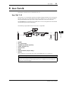 91
91
-
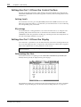 92
92
-
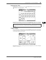 93
93
-
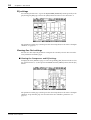 94
94
-
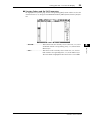 95
95
-
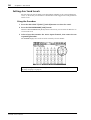 96
96
-
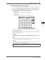 97
97
-
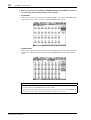 98
98
-
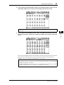 99
99
-
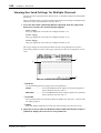 100
100
-
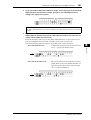 101
101
-
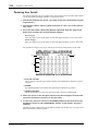 102
102
-
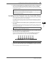 103
103
-
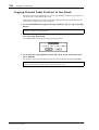 104
104
-
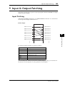 105
105
-
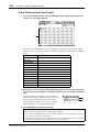 106
106
-
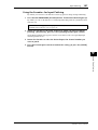 107
107
-
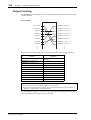 108
108
-
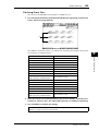 109
109
-
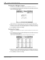 110
110
-
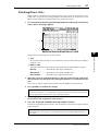 111
111
-
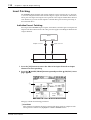 112
112
-
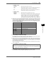 113
113
-
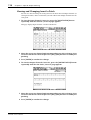 114
114
-
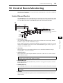 115
115
-
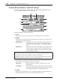 116
116
-
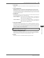 117
117
-
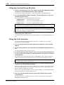 118
118
-
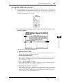 119
119
-
 120
120
-
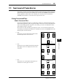 121
121
-
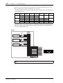 122
122
-
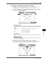 123
123
-
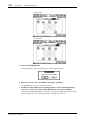 124
124
-
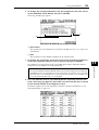 125
125
-
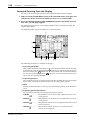 126
126
-
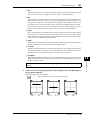 127
127
-
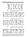 128
128
-
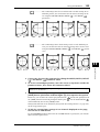 129
129
-
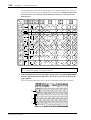 130
130
-
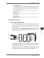 131
131
-
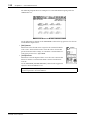 132
132
-
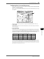 133
133
-
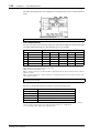 134
134
-
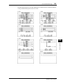 135
135
-
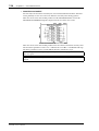 136
136
-
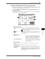 137
137
-
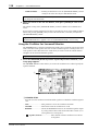 138
138
-
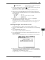 139
139
-
 140
140
-
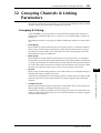 141
141
-
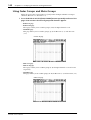 142
142
-
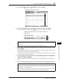 143
143
-
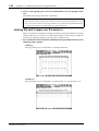 144
144
-
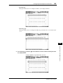 145
145
-
 146
146
-
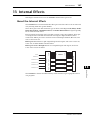 147
147
-
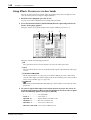 148
148
-
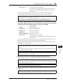 149
149
-
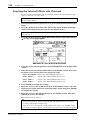 150
150
-
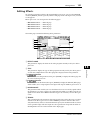 151
151
-
 152
152
-
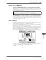 153
153
-
 154
154
-
 155
155
-
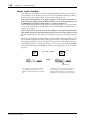 156
156
-
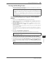 157
157
-
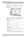 158
158
-
 159
159
-
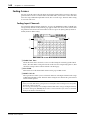 160
160
-
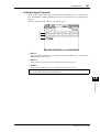 161
161
-
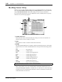 162
162
-
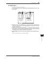 163
163
-
 164
164
-
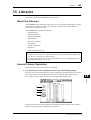 165
165
-
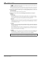 166
166
-
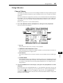 167
167
-
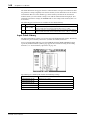 168
168
-
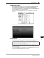 169
169
-
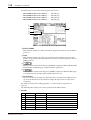 170
170
-
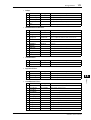 171
171
-
 172
172
-
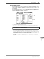 173
173
-
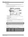 174
174
-
 175
175
-
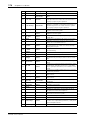 176
176
-
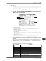 177
177
-
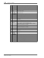 178
178
-
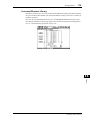 179
179
-
 180
180
-
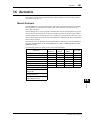 181
181
-
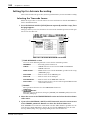 182
182
-
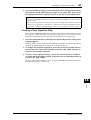 183
183
-
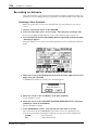 184
184
-
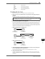 185
185
-
 186
186
-
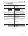 187
187
-
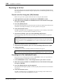 188
188
-
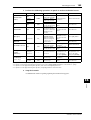 189
189
-
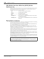 190
190
-
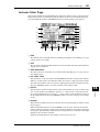 191
191
-
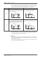 192
192
-
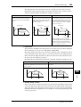 193
193
-
 194
194
-
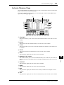 195
195
-
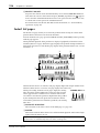 196
196
-
 197
197
-
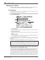 198
198
-
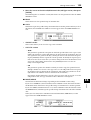 199
199
-
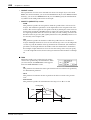 200
200
-
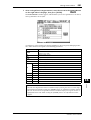 201
201
-
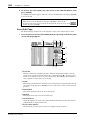 202
202
-
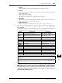 203
203
-
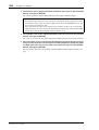 204
204
-
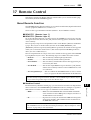 205
205
-
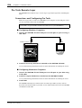 206
206
-
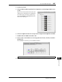 207
207
-
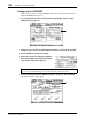 208
208
-
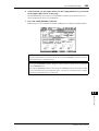 209
209
-
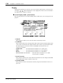 210
210
-
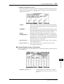 211
211
-
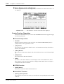 212
212
-
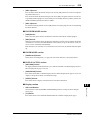 213
213
-
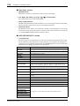 214
214
-
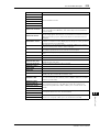 215
215
-
 216
216
-
 217
217
-
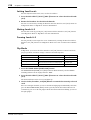 218
218
-
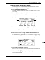 219
219
-
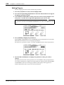 220
220
-
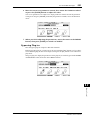 221
221
-
 222
222
-
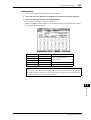 223
223
-
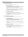 224
224
-
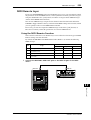 225
225
-
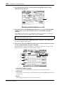 226
226
-
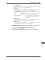 227
227
-
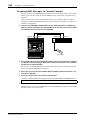 228
228
-
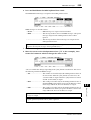 229
229
-
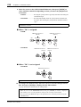 230
230
-
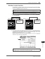 231
231
-
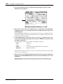 232
232
-
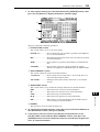 233
233
-
 234
234
-
 235
235
-
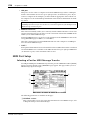 236
236
-
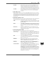 237
237
-
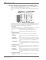 238
238
-
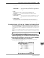 239
239
-
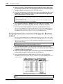 240
240
-
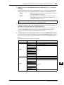 241
241
-
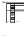 242
242
-
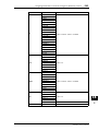 243
243
-
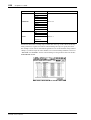 244
244
-
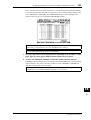 245
245
-
 246
246
-
 247
247
-
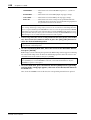 248
248
-
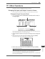 249
249
-
 250
250
-
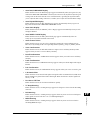 251
251
-
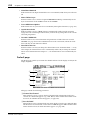 252
252
-
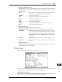 253
253
-
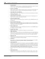 254
254
-
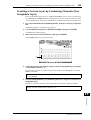 255
255
-
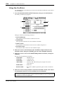 256
256
-
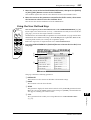 257
257
-
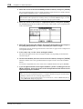 258
258
-
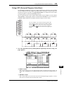 259
259
-
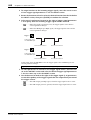 260
260
-
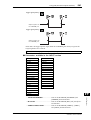 261
261
-
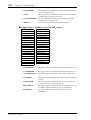 262
262
-
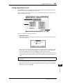 263
263
-
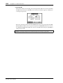 264
264
-
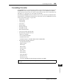 265
265
-
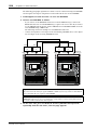 266
266
-
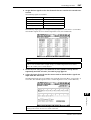 267
267
-
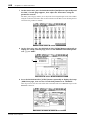 268
268
-
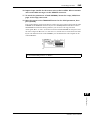 269
269
-
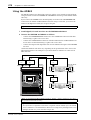 270
270
-
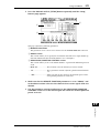 271
271
-
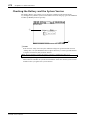 272
272
-
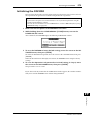 273
273
-
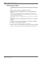 274
274
-
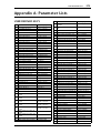 275
275
-
 276
276
-
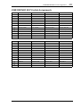 277
277
-
 278
278
-
 279
279
-
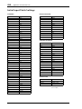 280
280
-
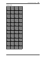 281
281
-
 282
282
-
 283
283
-
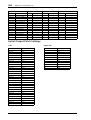 284
284
-
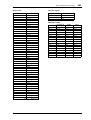 285
285
-
 286
286
-
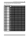 287
287
-
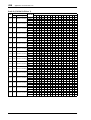 288
288
-
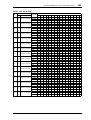 289
289
-
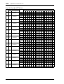 290
290
-
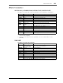 291
291
-
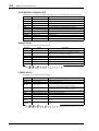 292
292
-
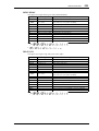 293
293
-
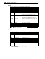 294
294
-
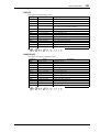 295
295
-
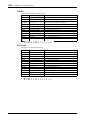 296
296
-
 297
297
-
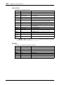 298
298
-
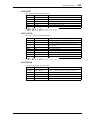 299
299
-
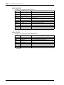 300
300
-
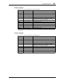 301
301
-
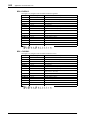 302
302
-
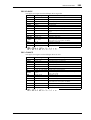 303
303
-
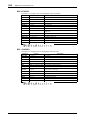 304
304
-
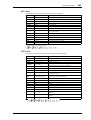 305
305
-
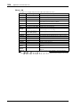 306
306
-
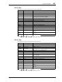 307
307
-
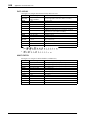 308
308
-
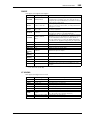 309
309
-
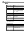 310
310
-
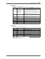 311
311
-
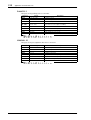 312
312
-
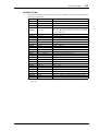 313
313
-
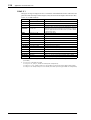 314
314
-
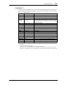 315
315
-
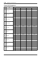 316
316
-
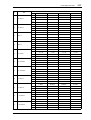 317
317
-
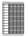 318
318
-
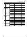 319
319
-
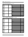 320
320
-
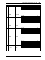 321
321
-
 322
322
-
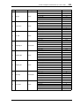 323
323
-
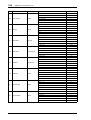 324
324
-
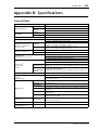 325
325
-
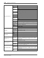 326
326
-
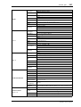 327
327
-
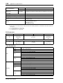 328
328
-
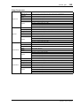 329
329
-
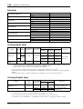 330
330
-
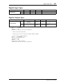 331
331
-
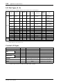 332
332
-
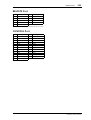 333
333
-
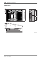 334
334
-
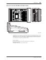 335
335
-
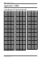 336
336
-
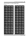 337
337
-
 338
338
-
 339
339
-
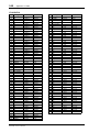 340
340
-
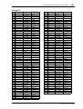 341
341
-
 342
342
-
 343
343
-
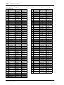 344
344
-
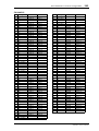 345
345
-
 346
346
-
 347
347
-
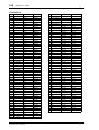 348
348
-
 349
349
-
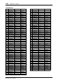 350
350
-
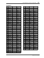 351
351
-
 352
352
-
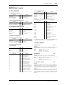 353
353
-
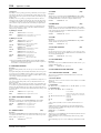 354
354
-
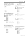 355
355
-
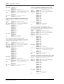 356
356
-
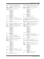 357
357
-
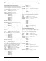 358
358
-
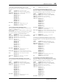 359
359
-
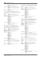 360
360
-
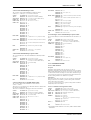 361
361
-
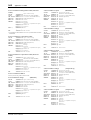 362
362
-
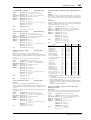 363
363
-
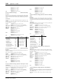 364
364
-
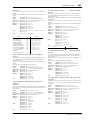 365
365
-
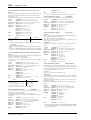 366
366
-
 367
367
-
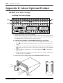 368
368
-
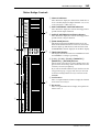 369
369
-
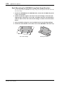 370
370
-
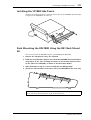 371
371
-
 372
372
-
 373
373
-
 374
374
-
 375
375
-
 376
376
-
 377
377
-
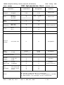 378
378
-
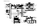 379
379
-
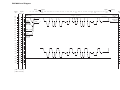 380
380
-
 381
381
-
 382
382


Yamaha DM1000 Instrukcja obsługi
- Kategoria
- Dodatkowy sprzęt muzyczny
- Typ
- Instrukcja obsługi
w innych językach
- čeština: Yamaha DM1000 Návod k obsluze
- español: Yamaha DM1000 El manual del propietario
- italiano: Yamaha DM1000 Manuale del proprietario
- Deutsch: Yamaha DM1000 Bedienungsanleitung
- svenska: Yamaha DM1000 Bruksanvisning
- português: Yamaha DM1000 Manual do proprietário
- français: Yamaha DM1000 Le manuel du propriétaire
- Türkçe: Yamaha DM1000 El kitabı
- English: Yamaha DM1000 Owner's manual
- dansk: Yamaha DM1000 Brugervejledning
- русский: Yamaha DM1000 Инструкция по применению
- Nederlands: Yamaha DM1000 de handleiding
- română: Yamaha DM1000 Manualul proprietarului
Powiązane dokumenty
-
Yamaha DM1000 Instrukcja obsługi
-
Yamaha 01V96i Instrukcja obsługi
-
-
-
Yamaha DM2000 Instrukcja obsługi
-
-
-
-
-
Yamaha MSR100 Instrukcja obsługi
Inne dokumenty
-
LD AM 8 Instrukcja obsługi
-
-
Panasonic DMWXLR1 Instrukcja obsługi
-
Sharp CP-LS100 Instrukcja obsługi
-
Sony XLR-K2M Instrukcja obsługi
-
Sigma R500T EOX Remote 500 Smart Control Center Instrukcja obsługi
-
Sony XLR-K1M Instrukcja obsługi
-
Phase Technology HV101-II Instrukcja obsługi
-
Sigma EOX REMOTE 500 E-Bike Instrukcja obsługi
-
Apogee Groove Skrócona instrukcja obsługi