Triton 880W Trimmer Router 1/4 Inch/ 8mm Instrukcja obsługi
- Typ
- Instrukcja obsługi

Version date: 26.08.22
tritontools.com
TMNRTR
880W Trimmer Router
1/4"/ 8mm
Operating & Safety Instructions
Bedienings- en
veiligheidsvoorschriften
Instructions d’utilisation
et consignes de sécurité
Instrucciones de
uso y de seguridad
Instrukcja obsługi
i bezpieczeństwa
Sicherheits- und
Bedienungsanleitung
Instruções de
Operação e Segurança
Инструкции по эксплуатации и
правила техники безопасности
Istruzioni per l’uso
e la sicurezza
817698_OwnerManual.indd 1817698_OwnerManual.indd 1 26/08/2022 15:0226/08/2022 15:02

2
7
8
9 1
2
3
4
5
6
10
11
12 13 14
16
17
18
12
15
UK
EU
817698_OwnerManual.indd 2817698_OwnerManual.indd 2 26/08/2022 15:0226/08/2022 15:02

3
10 11
22
9 19 20
21
22
23 24
2525 2627
12
16
17
18
12
817698_OwnerManual.indd 3817698_OwnerManual.indd 3 26/08/2022 15:0226/08/2022 15:02

4
EN
25
29
31
33 34 3532
30 28
817698_OwnerManual.indd 4817698_OwnerManual.indd 4 26/08/2022 15:0226/08/2022 15:02

5
EN
43
44 45 36
37
8
8
37
38
38
39
46
7
42
41
40
817698_OwnerManual.indd 5817698_OwnerManual.indd 5 26/08/2022 15:0226/08/2022 15:02

6
EN
Fig. II
Fig. I
Fig. III
47
36
45
43
48
28 9
18
48
17 32
16 1617
52
817698_OwnerManual.indd 6817698_OwnerManual.indd 6 26/08/2022 15:0326/08/2022 15:03

7
EN
0
1
2
3
4
5
Fig. IV
Fig. V
A
33
5
33
6
49
50 51 4
B
Fig. VI
817698_OwnerManual.indd 7817698_OwnerManual.indd 7 26/08/2022 15:0326/08/2022 15:03

8
Fig. X
Fig. XI
Fig. IX
2
3
41
Fig. VII
130mm
0mm
130mm
Fig. VIII
47
7
43
44
817698_OwnerManual.indd 8817698_OwnerManual.indd 8 26/08/2022 15:0326/08/2022 15:03

9
!
Fig. XIII
Fig. XIV Fig. XV
Fig. XII
AB C D
817698_OwnerManual.indd 9817698_OwnerManual.indd 9 26/08/2022 15:0326/08/2022 15:03

10
Fig. XVI
Fig. XVIII
Fig. XIX Fig. XX
Fig. XVII
7
43
42
41
40
817698_OwnerManual.indd 10817698_OwnerManual.indd 10 26/08/2022 15:0326/08/2022 15:03

11
49mm
59mm
49mm
66mm
100mm
53mm
83mm
120m
m
Fig. XXV
Fig. XXIV
Fig. XXIII
Fig. XXI Fig. XXII
43
a
b
c
49
48
a
b
817698_OwnerManual.indd 11817698_OwnerManual.indd 11 26/08/2022 15:0426/08/2022 15:04

12
EN
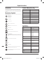
VVolts
~, a.c. Alternating current
A, mA Ampere, milli-Amp
n0No load speed
nRated speed
°Degrees
ØDiameter
Hz Hertz
W, kW Watt, kilowatt
/min or min-1 Operations per minute
dB(A) Decibel sound level (A weighted)
m/s² Metres per second squared (vibration magnitude)
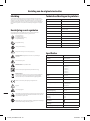
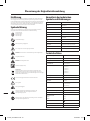
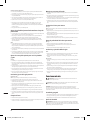
Technical Abbreviations Key
Wear hearing protection
Wear eye protection\
Wear breathing protection
Wear head protection
Wear hand protection
Read instruction manual
DO NOT use in rain or damp environments!
WARNING: Moving parts can cause crush and cut injuries.
Toxic fumes or gases!
WARNING: Sharp blades or teeth!
Class II construction (double insulated for additional protection)
Environmental Protection
Waste electrical products should not be disposed of with household waste. Please
recycle where facilities exist. Check with your local authority or retailer for recycling
advice.
Conforms to relevant legislation and safety standards.
Caution!
Be aware of kickback!
Always disconnect from the power supply when adjusting, changing accessories,
cleaning, carrying out maintenance and when not in use!
Do not touch the blades before the tool is disconnected from the supply and the
blades have come to complete stop
Description of Symbols
The rating plate on your tool may show symbols. These represent important information about the
product or instructions on its use.
Specication
Model no: TMNRTR
Voltage: 220-240 V, 50/60 Hz
Power: 880W
No load speed: 11,500-31,000min-1
6 speed setting (1-6): 1) 11,500min-1
2) 16,500min-1
3) 21,000min-1
4) 25,000min-1
5) 29,000min-1
6) 31,000min-1
Collets: 1/4” & 8mm
Max cutter diameter: 30mm
Max cutter shank: 8mm
Plunge adjustment: 1) Free plunge
2) Table height winder
3) Micro winder
Plunge range: 0-40mm
Parallel fence range: 0-130mm
Fence rod diameter: 8mm
Dust extraction port dimensions:
Inner:
Outer:
35mm
40mm
Insulation class:
Cord length: 3m
Ingress protection: IP20
Thank you for purchasing this Triton tool. This manual contains information necessary for
safe and effective operation of this product. This product has unique features and, even if
you are familiar with similar products, it is necessary to read this manual carefully to ensure
you fully understand the instructions. Ensure all users of the tool read and fully understand
this manual.
Original Instructions
Introduction
817698_OwnerManual.indd 12817698_OwnerManual.indd 12 26/08/2022 15:0426/08/2022 15:04

13
EN
WARNING: Always wear ear protection where the sound level exceeds 85dB(A) and limit the
time of exposure if necessary. If sound levels are uncomfortable, even with ear protection, stop using
the tool immediately and check the ear protection is correctly tted and provides the correct level of
sound attenuation for the level of sound produced by your tool.
WARNING: User exposure to tool vibration can result in loss of sense of touch, numbness,
tingling and reduced ability to grip. Long-term exposure can lead to a chronic condition. If necessary,
limit the length of time exposed to vibration and use anti-vibration gloves. Do not operate the tool
with hands below a normal comfortable temperature, as vibration will have a greater effect. Use the
gures provided in the specication relating to vibration to calculate the duration and frequency of
operating the tool.
Sound and vibration levels in the specication are determined according to international standards.
The gures represent normal use for the tool in normal working conditions. A poorly maintained,
incorrectly assembled, or misused tool, may produce increased levels of noise and vibration. www.
osha.europa.eu provides information on sound and vibration levels in the workplace that may be
useful to domestic users who use tools for long periods of time.
The declared vibration total value has been measured in accordance with a standard test method
and may be used for comparing one tool with another. The declared vibration total value may also be
used in a preliminary assessment of exposure.
WARNING: The vibration emission during actual use of the power tool can differ from the
declared total value depending on the ways in which the tool is used. There is the need to identify
safety measures to protect the operator that are based on an estimation of exposure in the actual
conditions of use (taking account of all parts of the operating cycle such as the times when the tool is
switched off and when it is running idle in addition to the trigger time).
Carefully read and understand this manual and any label attached to the tool before use. Keep these
instructions with the product for future reference. Ensure all persons who use this product are fully
acquainted with this manual.
Even when used as prescribed it is not possible to eliminate all residual risk factors. Use with caution.
If you are at all unsure of the correct and safe manner in which to use this tool, do not attempt to
use it.
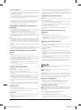
General Power Tool Safety Warnings
WARNING: Read all safety warnings, instructions, illustrations and specications provided
with this power tool. Failure to follow all instructions listed below may result in electric shock, re
and/or serious injury.
Save all warnings and instructions for future reference.
The term “power tool” in the warnings refers to your mains-operated (corded) power tool or battery-
operated (cordless) power tool.
1) Work area safety
a) Keep work area clean and well lit. Cluttered or dark areas invite accidents.
b) Do not operate power tools in explosive atmospheres, such as in the presence of
ammable liquids, gases or dust. Power tools create sparks which may ignite the dust or
fumes.
c) Keep children and bystanders away while operating a power tool. Distractions can cause
you to lose control.
2) Electrical safety
a) Power tool plugs must match the outlet. Never modify the plug in any way. Do not use
any adapter plugs with earthed (grounded) power tools. Unmodied plugs and matching
outlets will reduce risk of electric shock.
b) Avoid body contact with earthed or grounded surfaces, such as pipes, radiators, ranges
and refrigerators. There is an increased risk of electric shock if your body is earthed or
grounded.
c) Do not expose power tools to rain or wet conditions. Water entering a power tool will
increase the risk of electric shock.
d) Do not abuse the cord. Never use the cord for carrying, pulling or unplugging the power
tool. Keep cord away from heat, oil, sharp edges or moving parts. Damaged or entangled
cords increase the risk of electric shock.
e) When operating a power tool outdoors, use an extension cord suitable for outdoor use.
Use of a cord suitable for outdoor use reduces the risk of electric shock.
f) If operating a power tool in a damp location is unavoidable, use a residual current
device (RCD) protected supply. Use of an RCD reduces the risk of electric shock.
g) Use proper extension cord. Make sure your extension cord is in good condition. When
using an extension cord, be sure to use one heavy enough to carry the current your
product will draw. An undersized cord will cause a drop in line voltage resulting in loss of
power and overheating.
3) Personal safety
a) Stay alert, watch what you are doing and use common sense when operating a power
tool. Do not use a power tool while you are tired or under the inuence of drugs,
alcohol or medication. A moment of inattention while operating power tools may result in
serious personal injury.
b) Use personal protective equipment. Always wear eye protection. Protective equipment
such as a dust mask, non-skid safety shoes, hard hat or hearing protection used for appropriate
conditions will reduce personal injuries.
c) Prevent unintentional starting. Ensure the switch is in the OFF-position before
connecting to power source and/or battery pack, picking up or carrying the tool. Carrying
power tools with your nger on the switch or energising power tools that have the switch ON
invites accidents.
d) Remove any adjusting key or wrench before turning the power tool ON. A wrench or a
key left attached to a rotating part of the power tool may result in personal injury.
e) Do not overreach. Keep proper footing and balance at all times. This enables better
control of the power tool in unexpected situations.
f) Dress properly. Do not wear loose clothing or jewellery. Keep your hair and clothing
away from moving parts. Loose clothes, jewellery or long hair can be caught in moving parts.
g) If devices are provided for the connection of dust extraction and collection facilities,
ensure these are connected and properly used. Use of dust collection can reduce dust-
related hazards.
h) Do not let familiarity gained from frequent use of tools allow you to become
complacent and ignore tool safety principles. A careless action can cause severe injury
within a fraction of a second.
4) Power tool use and care
a) Do not force the power tool. Use the correct power tool for your application. The correct
power tool will do the job better and safer at the rate for which it was designed.
b) Do not use the power tool if the switch does not turn it ON and OFF. Any power tool that
cannot be controlled with the switch is dangerous and must be repaired.
c) Disconnect the plug from the power source and/or remove the battery pack, if
detachable, from the power tool before making any adjustments, changing accessories,
or storing power tools. Such preventive safety measures reduce the risk of starting the power
tool accidentally.
d) Store idle power tools out of the reach of children and do not allow persons unfamiliar
with the power tool or these instructions to operate the power tool. Power tools are
dangerous in the hands of untrained users.
e) Maintain power tools and accessories. Check for misalignment or binding of moving
parts, breakage of parts and any other condition that may affect the power tool’s
operation. If damaged, have the power tool repaired before use. Many accidents are
caused by poorly maintained power tools.
f) Keep cutting tools sharp and clean. Properly maintained cutting tools with sharp cutting
edges are less likely to bind and are easier to control.
g) Use the power tool, accessories and tool bits, etc. in accordance with these instructions,
taking into account the working conditions and the work to be performed. Use of the
power tool for operations different from those intended could result in a hazardous situation.
h) Keep handles and grasping surfaces dry, clean and free from oil and grease. Slippery
handles and grasping surfaces do not allow for safe handling and control of the tool in
unexpected situations.
Dimensions (L x W x H):
with plunge base: 290 x 280 x 150mm
with trimmer base: 260 x 150 x 96mm
no base: 245 x 80 x 125mm
Weight: 2.9kg
As part of our ongoing product development, specications of Triton products
may alter without notice.
Sound & vibration information
Sound pressure LPA 85dB(A)
Sound power LWA 96dB(A)
Uncertainty K 3dB
Weighted vibration ah6.167m/s²
Uncertainty K 1.5m/s²
The sound intensity level for the operator may exceed 85dB(A) and sound protection
measures are necessary.
817698_OwnerManual.indd 13817698_OwnerManual.indd 13 26/08/2022 15:0426/08/2022 15:04

14
EN
5) Service
a) Have your power tool serviced by a qualied repair person using only identical
replacement parts. This will ensure that the safety of the power tool is maintained.
Additional Safety for Routers
WARNING:
• Hold the power tool by insulated gripping surfaces only, because the cutter may contact its
own cord. Cutting a “live” wire may make exposed metal parts of the power tool “live” and could
give the operator an electric shock.
• Use clamps or another practical way to secure and support the workpiece to a stable
platform. Holding the work by your hand or against the body leaves it unstable and may lead to
loss of control.
• If the replacement of the supply cord is necessary, this has to be done by the manufacturer
or his agent in order to avoid a safety hazard.
• It is strongly recommended that the tool always be supplied via a residual current device
with a rated residual current of 30 mA or less.
a) Use safety equipment including safety goggles or shield, ear protection, dust mask and
protective clothing including safety gloves
b) Cloths, cord, string etc should never be left around the work area
c) Ensure the mains supply voltage is the same as the tool rating plate voltage
d) Ensure any cable extensions used with this tool are in a safe electrical condition, and have
the correct ampere rating for the tool
e) Completely unwind cable drum extensions to avoid potential overheating
f) Use appropriate detectors to determine if utility cables or pipes are below the surface of
the work area. Consult utility companies for assistance if necessary. Contact with electric cables
can lead to electric shock and re. Damaging a gas pipe can lead to explosion. Contact with water
lines can lead to major property damage
g) Ensure embedded objects such as nails and screws have been removed from the workpiece
before commencing operation
h) Handle router bits with care as they can be extremely sharp
i) Before use, check the bit carefully for signs of damage or cracks. Replace damaged or cracked
bits immediately
j) Ensure router cutters/bits are sharp and maintained correctly. Dull cutting edges can lead to
uncontrolled situations including stalling, increased heat and possible injury
k) ALWAYS use both handles and maintain a rm grip on the router before proceeding with
any work
l) Keep handles and gripping surfaces dry, clean and free of oil and grease to ensure the tool
can be securely held in use
m) Before using the tool to make a cut, switch on and let it run for a while. Vibration could
indicate an improperly installed bit
n) Take notice of the direction of rotation of the bit and the direction of feed
o) Keep your hands away from the routing area and router bit cutter. Hold the auxiliary handle
or an insulated gripping surface with your second hand
p) NEVER start the router while the cutter is touching the workpiece
q) Ensure the plunge spring is always tted when using hand-held
r) Ensure the cutter has completely stopped before plunging to the collet lock position
s) The maximum speed of the router bit/cutter must be at least as high as the maximum
speed of the power tool
t) Parts of the router bits may become hot during operation. Do not handle immediately after
use to avoid risk of burns
u) Do not allow parts to come into contact with combustible materials
v) The shank size of the router cutter/bit must be matched to the exact same size collet
tted to the router. Incorrectly tted router cutter/bits will rotate irregularly and have increased
vibration that could lead to loss of control
w) DO NOT press the spindle lock button, or attempt to switch the tool into bit change mode
while the router is operating
x) Keep pressure constant while cutting into the workpiece, allowing the router bit cutter to
dictate the speed of cut. DO NOT force the tool and overload the motor
y) Ensure rating labels and safety warnings on the tool remain clear to read and are replaced
if marked or damaged
z) When operating the router, be prepared for the router bit cutter stalling in the workpiece
and causing loss of control. Always ensure the router is rmly held and the on/off switch is
immediately released in such circumstances
• After switching on the router, check the router bit is rotating evenly (not ‘wobbling’) and
there is no additional vibration due to the router bit being incorrectly tted. Operating the
router with an incorrectly tted router bit can lead to loss of control and severe injury
• EXTREME care must be taken when using cutters with a diameter greater than 2” (50mm).
Use very slow feed rates and/or multiple shallow cuts to avoid overloading the motor
• ALWAYS switch off and wait until the bit has come to a complete standstill before removing
the machine from the workpiece
• Disconnect from the power supply before carrying out any adjustment, servicing or
maintenance
WARNING: Dust generated by using power tools can be toxic. Some materials may be chemically
treated or coated and be a toxic hazard. Some natural and composite materials may contain toxic
chemicals. Some older paints may contain lead and other chemicals. Avoid prolonged exposure to
dust generated from operating a router. DO NOT allow dust to get onto skin or eyes and do not allow
the dust to enter your mouth to prevent absorption of harmful chemicals. Where possible, work in
a well-ventilated area. Use a suitable dust mask and dust extraction system where possible. Where
there is a higher frequency of exposure, it is more critical that all safety precautions are followed and
a higher level of personal protection is used.
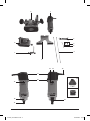
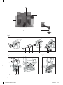
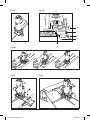
Product Familiarisation
1. Router
2. Spanner
3. Collet
4. Hex Key
5. Guide Rails
6. Guide Fence
7. Roller Guide
8. Trimmer Base
9. Plunge Base
10. ON/OFF Switch
11. Speed Dial
12. Brush Access Covers
13. Motor Vents
14. Power Cord
15. Power Plug
16. Spindle Lock Button
17. Collet Nut
18. Securing Hole
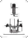
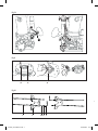
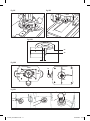
19. Dust Extraction Spout
20. Micro Winder
21. Micro Adjustment Guide
22. Handle
23. Guide Rail Slot
24. Plunge Lock Lever
25. Guide Rail Locking Knob
26. Base of Plunge Base
27. Plunge Base Plate
28. Plunge Base Locking Knob
29. Depth Stop Lock
30. Depth Stop
31. Depth Turret
32. Table Height Micro Winder Connector
33. Guide Bush Locking Screw
34. Dust Extraction Spout Connection Screw
35. Plunge Base Plate Screw
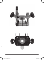
36. Trimmer Base Locking Knob
37. Trimmer Depth Locking Knob
38. Trimmer Base Plate
39. Trimmer Base Plate Screw
40. Guide Bearing
41. Roller Guide Adjustment Locking Knob
42. Roller Guide Adjustment Knob
43. Roller Guide Locking Knob
44. Washer
45. Trimmer Base Guard
46. Trimmer Depth Micro Adjustment Dial
47. Roller Guide Alignment Channel
817698_OwnerManual.indd 14817698_OwnerManual.indd 14 26/08/2022 15:0426/08/2022 15:04

15
EN
48. Router Bit (not supplied)
49. Guide Bush (not supplied)
50. Spring Washer
51. Hex Screw
52. Table Height Winder
Figures XII and XIII
a Template
b Workpiece
c Offset
Intended Use
A mains-powered mini router intended for routing proles, edges, grooves, holes and for copy
routing in plastic, light building materials, and wood. Predominantly for hand held use.
Note: Not intended for commercial use.
Unpacking Your Product
• Carefully unpack and inspect your product. Fully familiarise yourself with all its features and
functions
• Ensure all parts of the product are present and in good condition
• If any parts are missing or damaged, have such parts replaced before attempting to use this
product
Before Use
WARNING: Ensure the tool is disconnected from the power supply before attaching/
changing any accessories or making any adjustments.
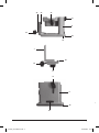
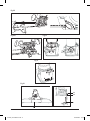
Collet & router bit installation
WARNING: Wear protective gloves when inserting and removing router bits due to the sharp
edges of the cutters.
WARNING: Always use cutters and bits with the correct size shank for the chosen collet size.
Note: It is easiest to install a cutter prior to tting the router to a base; however, it is possible to
change the Router Bit (not supplied) (48) when attached to a base.
See Fig. I
1. Press the Spindle Lock Button (16) then rotate the Collet Nut (17) until the spindle lock engages
2. Slacken the Collet Nut, using the supplied Spanner (2) if required, and remove the Collet Nut
3. Ensure the correct size Collet is chosen to match the required Router Bit (48) then place the Collet
into the spindle, then reapply the Collet Nut
4. With the correct Collet in place and Collet Nut attached but slackened, insert the Router Bit into
the Collet, ensuring that at least half of the Router Bit’s shaft is inserted
5. Tighten the Collet Nut with the Spanner, ensuring that the Router Bit cutter has 1-2mm clearance
from the Collet and is not butted tight against the Collet or the Collet Nut; vibration from the
cutter could vibrate the Collet Nut and cause it to loosen during use
WARNING: DO NOT over-tighten the Collet Nut! This could cause damage to the Collet, Collet
Nut, external thread and Spindle Lock.
Note: Do not tighten the Collet Nut with no Router Bit tted. This can bend and damage the Collet.
Keep the Collet Nut partially screwed in until a Router Bit is tted. Be aware of the spring in the
spindle that keeps pressure on the Collet up against the Collet Nut. When installing the Collet, a
small amount of pressure is required when applying the Collet Nut to the spindle drive thread.
6. To remove a Router Bit, engage the Spindle Lock by pressing the Spindle Lock Button then slacken
the Collet Nut with the Spanner
7. With the Collet Nut sufciently slackened, the Router Bit can be removed
WARNING: ALWAYS keep the Collet, Collet Nut, spindle drive thread and Router Bit shank clean
and free of oil and grease to ensure a reliable and secure tting.
Fitting to plunge base
Note: If the Router (1) is attached to the Trimmer Base (8), remove the Trimmer Base before
attempting to t the router to the Plunge Base (9).
1. Ensure the Plunge Base Locking Knob (28) is wound out so the screw is not protruding into the
base
2. Align the Router (1) so the Securing Hole (18) is directly above the Plunge Base Locking Knob
(Fig. II)
3. Place the Router into the cradle of the Plunge Base
4. Tighten the Plunge Base Locking Knob (Fig. II) to secure the Router in the Plunge Base
Dust extraction
IMPORTANT: Dust from certain materials can be toxic. Before using the Router (1), attach a dust
extraction system or vacuum cleaner to the Dust Extraction Spout (19) (Fig. III), which is tted to the
Plunge Base (9), and ALWAYS wear respiratory protection. If no workshop dust extraction system
is available when using the Plunge Base, clean and vacuum frequently to prevent the build-up of
dust and chippings.
Note: The Dust Extraction Spout can be removed, if required, by unscrewing the two Dust Extraction
Spout Connection Screws (34). This will allow better access to cleaning hard-to-get-at places on the
Plunge Base when cleaning.
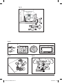
Adjusting the depth of cut
There are two ways to adjust the depth of cut:
• Free Plunge, for conventional and fast depth adjustment
• Micro Adjuster, for precise depth setting throughout the full plunge range
Free plunge
1. With a chosen Router Bit (48) tted and the Router (1) attached to the Plunge Base (9), disengage
the Plunge Lock Lever (24) (Fig. IV)
2. Using the Handles (22), plunge the router down to the required plunge depth
3. Engage the Plunge Lock Lever to lock the router at the required depth
Micro adjuster
1. With a chosen Router Bit (48) tted and the Router (1) attached to the Plunge Base (9), disengage
the Plunge Lock Lever (24) (Fig. IV)
2. Turn the Micro Winder (20) until the router bit is at the depth required
Note: Turn clockwise to increase cut depth and anti-clockwise to reduce cut depth. A full revolution of
the Micro Winder is a depth adjustment of 1.5mm (1/16”). The Micro Adjustment Guide (21) can be
used to set a point of reference when gauging a full revolution.
3. Engage the Plunge Lock Lever when the router is at the required depth, particularly for heavy cuts
Depth stop & turret
• The Depth Stop Lock (29) and Depth Turret (31) enable accurate pre-setting of three different cut
depths, each stepped at 5mm (3/64”) (Fig. IV)
Zeroing the router:
1. With a chosen Router Bit (48) tted and the Router (1) attached to the Plunge Base (9), place the
Router on a at surface then disengage the Plunge Lock Lever (24) (Fig. IV)
2. Rotate the Depth Turret (31) until the 0 step is beneath the Depth Stop (30)
3. Disengage the Depth Stop Lock (29) to release the Depth Stop
4. Plunge the Router down until the tip of the Router Bit touches the at surface
5. Engage the Depth Stop Lock so the Depth Stop is locked in its current position
Adjusting the depth turret:
• The Depth Turret (31) allows 3 different plunge depths to be congured for fast switching during
use: 5mm, 10mm and 15mm (3/64 x 25/64 x 19/32”)
• This can speed up operations or allow a 3-cut approach to reaching the nal required depth of cut
• Using the Depth Turret is particularly important when the workpiece is more difcult to cut, i.e.
harder wood or when a better nish is required
• If the Depth Turret becomes loose, tighten the screw in the centre
1. After zeroing the router (see “Zeroing the router”), the secured Depth Stop (30) now provides an
accurate datum and the depth of cut can be set by reference to the graduations etched into the
face of each depth on the Depth Turret (31) (Fig. IV)
2. Rotate the Depth Turret to the required depth
Custom depth using the depth stop
• The scale on the face of the Depth Stop (30) can be used to make adjustments to the Depth Stop
after the router has been zeroed (see “Zeroing the router”)
1. After zeroing the router on one of the turret stops, plunge the router to the zero depth and ensure
the Plunge Lock Lever (24) is engaged
2. Loosen the Depth Stop Lock and raise the Depth Stop to required depth then retighten the Depth
Stop Lock to set the new plunge depth
Notes:
• The exact depth required for a particular task, such as a hinge leaf, can be achieved by placing the
object/material of required plunge depth between the Depth Stop and the Depth Turret before
locking the Depth Stop Lock. The plunge will now be the precise depth required for the object/
material
• The gap between the end of the Depth Stop and the Turret Stop (31) will be the plunge depth
• The scale on the Depth Stop can be used to check changes in depth setting, but the actual cutting
depth is best measured by making a trial cut on scrap material. The scale should be used as an
approximate guide
817698_OwnerManual.indd 15817698_OwnerManual.indd 15 26/08/2022 15:0426/08/2022 15:04

16
EN
Fitting a guide bush for use with templates & jigs
See Fig. V
• An optional template guide bush kit is available for purchase from your Triton stockist
1. To install a Guide Bush (not supplied) (49), loosen the Guide Bush Locking Screws (33) and
ensure the rotating tabs are rotated away from the guide bush
2. Line the notches on the Guide Bush with the Guide Bush Locking Screws so that the guide bush
sits centre and ush against the Plunge Base Plate (27)
3. Rotate the tabs on the Guide Bush Locking Screws over the notches on the Guide Bush then
tighten the screws to secure the Guide Bush
4. To remove the Guide Bush, loosen the screws, rotate the tabs then remove the Guide Bush before
retightening the Guide Bush Locking Screws
Fitting & adjusting the guide fence
See Fig. VI, VII, VIII
Note: The Guide Fence (6) is for use with the Plunge Base (9) only
• The Guide Fence (6) can be assembled according to ‘A’ or ‘B’ (Fig. VI)
• Ensure the scale on one of the Guide Rails (5) is facing up when tightening the Hex Screws (51)
1. To t the Guide Fence, loosen the Guide Rail Locking Knobs (25) and insert the Guide Rails of the
assembled fence into the Guide Rail Slots (23) (Fig. VII)
2. Adjust the Guide Fence to the required distance from the cutter (Fig. VII), using the scale as an
approximate guide (Fig. VIII) if used in conguration A, and measured if used in conguration B
3. Ensure all Guide Rail Locking Knobs are tightened to secure the Guide Fence
• If required, faces on the Guide Fence can be removed and a batten can be attached to ensure a
completely straight Guide Fence. Always measure to the centre point of the cutter to ensure an
accurate cut
Beam trammel
• The diameter of the Guide Rail (5) is 8mm (5/16”)
• A compatible 8mm beam trammel (not supplied) could be tted to one of the rails and the rail
could then be tted into one of the Guide Rail Slots (23)
Table use
• When the Router (1) is tted to the Plunge Base (9) it can be used in a compatible router table
• See Fig. XXIV for the dimensions of the Plunge Base Plate Screws (35) for securing to a compatible
table
• The Plunge Base Plate (27) can be removed to allow tment to a compatible template or bracket.
Consult the router table manufacturer’s installation instructions
• The Plunge Base has a Table Height Micro Winder Connector (32) that will allow above-table
cutter height adjustment with a Triton Table Height Winder (52), if the table has an access hole
Fitting to trimmer base
See Fig. IX
Note: If the Router (1) is attached to the Plunge Base (9), remove the Plunge Base before attempting
to t the router to the Trimmer Base (8).
1. Ensure the Timmer Base Locking Knob (36) is wound out so the screw is not protruding into the
base
2. Align the Router (1) so the Securing Hole (18) is directly above the Trimmer Base Locking Knob
(Fig. IX)
3. Place the Router into the cradle of the Trimmer Base
4. Tighten the Trimmer Base Locking Knob (Fig. IX) to secure the Router in the Trimmer Base
Setting the depth of cut with the trimmer base
See Fig. X
1. Loosen the Trimmer Depth Locking Knob (37)
2. Turn the Trimmer Depth Micro Adjustment Dial (46) to adjust the cutter height to the required
depth
3. Lock the Trimmer Depth Locking Knob to secure the depth
Fitting & adjusting the roller guide
Notes:
• Lateral clearance: to adjust the amount of material removed by the cutter, adjust the horizontal
clearance between the workpiece and the Guide Bearing
• Height: adjust the vertical height of the cutter depending on the thickness of the material to be
cut and the router bit to be used
See Fig. XI and XII
1. To t the Roller Guide (7) to the Trimmer Base (8), loosen the Roller Guide Locking Knob (43)
2. Slide the Roller Guide onto the Trimmer Base, ensuring the guide is aligned with the Roller Guide
Alignment Channel (47) (Fig. XI) and the Washer (44) is on the outside of the Roller Guide
3. Adjust the Roller Guide to the required height then tighten the Roller Guide Locking Knob to
secure the roller guide (Fig. XII)
4. To adjust the Guide Bearing’s (40) horizontal position, loosen the Roller Guide Adjustment
Locking Knob (41) then adjust with the Roller Guide Adjustment Knob (42) (Fig. XII)
5. Tighten the Roller Guide Adjustment Locking Knob to secure the Guide Bearing in place
Operation
WARNING: Ensure the tool is disconnected from the power supply before attaching/
changing any accessories or making any adjustments.
WARNING: ALWAYS wear eye protection, adequate respiratory and hearing protection, as well as
suitable gloves when working with this tool.
IMPORTANT: Ensure the Motor Vents (13) and other vents of the tool are kept clean. Metallic swarf,
breglass, plaster and other particles and dust can damage the tool if allowed to enter the Motor
Vents. Use a vacuum cleaner to ensure the vents are clean. If necessary, blow out with compressed air.
Switching ON & OFF
1. To power the Router (1) ON, press the ON/OFF Switch (10) to the ‘I’ position
2. To power the Router OFF, press the ON/OFF Switch to the ‘O’ position
3. Always allow the tool to reach full speed before making a cut
Variable speed control
WARNING: NEVER operate router bits at speeds higher than their maximum rated speed. If bits
are used at higher speeds than their rated speed, they can break and y apart, potentially damaging
the tool, workpiece and causing serious personal injury.
• Control the rotation speed of the cutter by adjusting the Speed Dial (11)
• The highest speed is achieved when the number is set to 6
• The lowest speed is achieved when the number is set to 1
• Set the ideal speed for the material; consider the material and bit diameter
• Too slow a speed can result in the cutter leaving burn marks on the material
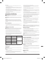
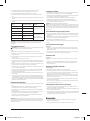
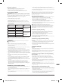
• See table below for the number to speed relationship on the dial and usage information
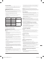
Number RPM Usage
111,500 Bits and cutters with a larger
diameter
216,500
321,000
425,000 Bits and cutters with a smaller
diameter. Laminates, plastics
and softwoods
529,000
631,000
IMPORTANT: Operating at reduced speed increases the risk of damage to the Router (1) as a result of
overload. Use very slow feed rates and/or multiple shallow cuts.
Hand-held operation
WARNING: To minimise the risk of kickback, the direction of routing must always be in
opposition to the cutter’s rotational direction.
Notes:
• Ensure all PPE/safety equipment is used when operating this tool
• Ensure the workpiece is securely clamped to prevent any movement during operation
• Hold the Router (1) rmly using both hands to control the Router and keep an even pressure and
movement when cutting
• The cutter rotates in a clockwise direction (A on Fig. XIII)
• When edge routing or trimming on the outside edge, ensure the workpiece is to the left of the
cutter (B and C on Fig. XIII) and work in an anticlockwise direction (Figs XIV, XV, XVI, XVIII, XIX, XX)
• When routing internal edges, ensure the edge to be cut is to the left of the cutter and work
around the internal shape (D on Fig. XIII) in a clockwise direction
• If cutting all the way through the material, x a sacricial board to the underside of the workpiece
• When edge cutting natural timbers, always pass along the end grain rst, then by the long grain.
If splintering or breakout occurs, this will be remedied when passing down the long grain
• Do not operate the Router upside down unless securely mounted in a well-guarded router table
• If a deep cut is required for a plunge cut, do not make the full depth for the rst pass. Instead,
make more passes with a shallower depth of cut and adjust the cutting depth gradually in smaller
increments. The Depth Stop (30) and Depth Turret (31) can be used for changing depths to pre-set
5mm (3/64”) increments
817698_OwnerManual.indd 16817698_OwnerManual.indd 16 26/08/2022 15:0426/08/2022 15:04

17
EN
Routing with the roller guide
• Use the Timmer Base (8) and Roller Guide (7) for routing edges with router bits without a guide
bearing or pilot
• Ensure the Router (1) is installed in the Trimmer Base with the Roller Guide (see ‘Fitting to
trimmer base’ and ‘Fitting & adjusting the roller guide’)
• Ensure the depth of cut is set as required (see ‘Setting the depth of cut with the trimmer base’)
1. Power the Router ON then guide the Router from the side toward the workpiece until the Guide
Bearing (40) contacts the edge of the workpiece (Figs XVI XVII)
2. Guide the Router along the workpiece’s edge, ensuring the base rests on the workpiece at the
correct angle
IMPORTANT: When using the Trimmer Base (8) with the Roller Guide (7), adjust the Guide Bearing
(40) (Fig. XVII) with enough vertical clearance from the cutter and consider cutter’s diameter
when setting the horizontal axis so the Guide Bearing can guide the cutter along the edge of the
workpiece.
Shaping or moulding
• If shaping or moulding without a parallel guide (Guide Fence (6) or batten), a router bit with a
guide bearing or pilot must be used (Figs XIV XV)
• Ensure the depth of cut is set as required (see ‘Before Use’ sections pertaining to setting the depth
of cut)
1. Power the Router (1) ON then guide the Router from the side toward the workpiece until the
guide bearing on the Router Bit (not supplied) (48) contacts the edge of the workpiece
2. Guide the Router along the workpiece’s edge, ensuring the base rests on the workpiece at the
correct angle
IMPORTANT: Excessive pressure could damage the workpiece.
Note: To prevent edge burn, clamp a sacricial piece of material of the same thickness as the
workpiece before and after the workpiece. Start the cutting on the rst sacricial piece, guide along
onto the workpiece then beyond to nish on the other sacricial piece. Doing this will prevent
beginning burn and end burn on the workpiece.
Routing with a parallel guide or guide fence
• Use the Guide Fence (6) assembled in conguration A or B (Fig. VI), fastened to the Plunge Base
(9) (see ‘Fitting & adjusting the guide fence’), for edge-parallel cuts or batten-parallel cuts (Figs
XIX and XX)
• Ensure the depth of cut is set as required (see ‘Before Use’ sections pertaining to setting the depth
of cut)
1. Adjust to required distance from the Guide Fence to the cutter
2. Power the Router (1) ON then guide the Router with a controlled feed and lateral pressure along
the workpiece’s edge
Routing with a batten guide
See Fig. XVIII
• A batten guide can be used when clamped on top of the workpiece (see Fig. XXIV for distances to
the edge of the bases from the centre of the cutter as an approximate guide)
• The Guide Fence (6) in conguration B (Fig. VI) can be used with the batten (Fig. XX)
• It is recommended that a test cut be performed on scrap material prior to using the workpiece
Freehand routing
See Fig. XXI
• The Router (1) can be used for creative freehand or signwriting work without the use of a guide
• Practise on scrap material before working on the workpiece
• Draw the design on the workpiece then router the design using shallow passes
Template & guide bush routing
See Fig. XXII and XXIII
• See ‘Fitting a guide bush for use with templates & jigs’
• Template patterns (Fig. XXII (a)) are used with a Guide Bush (not supplied) (49) to allow the Router
(1) to carve a pattern in the workpiece (Fig. XXII (b)) and are used for consistent, repeatable shapes
• When using a template and Guide Bush, the cut on the nal workpiece will differ from the space
in the template, and the Offset (Fig. XXIII (c)) of the Guide Bush must be considered prior to
cutting
• To work out the Offset, use this formula: Offset = Guide Bush outer diameter - Router Bit (48)
diameter
• Template patterns and jigs can be made out of a variety of materials such as hardboard, plywood,
plastic or metal
Table-mounted operation
• Fitting and operating this router on a compatible router table should be carried out in accordance
with the instructions supplied with the router table
• Ensure the Router (1) is tted to the Plunge Base (9) if using in a compatible router table
• A Triton Table Height Winder engages with the Table Height Micro Winder Connector (32) for
quick and easy above-the-table height adjustment when the router is table mounted, and there is
an access hole for the Height Winder
Accessories
• A full range of accessories, including router bits and guide bushes, is available from your Triton
stockist
• Spare parts can be obtained from toolsparesonline.com
Maintenance
WARNING: ALWAYS disconnect from the power supply before carrying out any inspection,
maintenance or cleaning.
General inspection
• Regularly check that all the xing screws are tight
• Prior to each use, inspect the supply cord of the tool for signs of damage or wear. Repairs should
be carried out by an authorised Triton service centre. This advice also applies to extension cords
used with this tool
Cleaning
• Keep your tool clean at all times. Dirt and dust will cause internal parts to wear quickly and
shorten the tool’s service life
• Clean the body of the tool with a soft brush, or dry cloth. If available, use clean, dry, compressed
air to blow through the ventilation holes
• Clean the tool casing with a soft, damp cloth using a mild detergent. Do not use alcohol, petrol or
strong cleaning agents
• Never use caustic agents to clean plastic parts
Lubrication
• All the bearings in this tool are lubricated with a sufcient amount of high-grade lubricant for the
life of the unit under normal conditions. Therefore, no further lubrication is required
Brushes
• Over time the carbon brushes inside the motor may become worn
• Excessively worn brushes may cause loss of power, intermittent failure, or visible sparking
To replace the brushes (Fig. XXV):
1. Loosen the Brush Access Covers (12) with a at tip screwdriver
2. Use the screwdriver to retrieve the brushes
3. Replace both brushes by aligning the rectangular shape of the brush with the slot then inserting
4. Replace the Brush Access Covers and tighten with a at tip screwdriver
Note: There may be some sparking after installing new brushes until the brushes have been bedded.
This should happen normally with short bursts of regular use.
Contact
For technical or repair service advice, please contact the helpline on (+44) 1935 382 222
Web: tritontools.com/en-GB/Support
UK Address:
Toolstream Ltd.
Boundary Way
Lufton Trading Estate
Yeovil, Somerset
BA22 8HZ, United Kingdom
EU Address:
Toolstream B.V.
De Keten
00004
5651 GJ
Eindhoven, Netherlands
Storage
• Store this tool in the supplied case, in a secure, dry location out of the reach of children
Disposal
Always adhere to national regulations when disposing of power tools that are no longer functional
and are not viable for repair.
• Do not dispose of power tools, or other waste electrical and electronic equipment (WEEE) with
household waste
• Contact your local waste disposal authority for information on the correct way to dispose of power
tools
817698_OwnerManual.indd 17817698_OwnerManual.indd 17 26/08/2022 15:0426/08/2022 15:04

18
EN
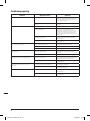
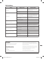
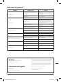
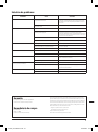
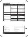
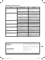
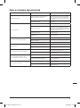
Troubleshooting
Problem Possible cause Solution
Inaccurate cutting prole Depth Stop (30) / depth (Trimmer Base) not correctly adjusted Ensure the Depth Stop/trimmer height corresponds to the
maximum amount of cut permitted by the Depth Turret (31) /
Trimmer Depth Micro Adjustment Dial (46)
Incorrectly tted or loose Router Bit/Collet/Collet Nut (48,
3 or 17)
Tighten Router Bit/Collet/Collet Nut and cutter assembly
Router (1) will not operate No supply of power Check that power is available at source
Brushes worn or sticking Disconnect power, open Brush Access Covers (12) and ensure
brushes are not damaged or heavily worn. If worn, replace
brushes (see ‘Brushes’ or have the tool serviced by an authorised
Triton service centre)
ON/OFF Switch (10) is faulty Have the tool serviced by an authorised Triton service centre
Motor components faulty or short circuited Have the tool serviced by an authorised Triton service centre
Router runs or cuts slowly Blunt or damaged cutter/Router Bit Re-sharpen or replace cutter/Router Bit
Speed Dial (11) set low Increase variable speed setting
Motor is overloaded Reduce pushing force on Router
Excessive vibration Incorrectly tted or loose Router Bit Re-t or tighten Router Bit and Collet Nut (17)
Bent or damaged Router Bit Replace Router Bit
Heavy sparking occurs inside motor housing Brushes not moving freely Disconnect power, remove brushes, clean or replace (see
‘Brushes’)
Damaged or worn motor Have the tool serviced by an authorised Triton service centre
Micro Winder (20) “clicks” or not adjusting on Plunge Base (9) Plunge Lock Lever (24) engaged Release Plunge Lock Lever
Reached end of adjustment range Reset Micro Winder and set depth with the Depth Stop
Makes an unusual sound Mechanical obstruction Have the tool serviced by an authorised Triton service centre
Damage to internal windings Have the tool serviced by an authorised Triton service centre
817698_OwnerManual.indd 18817698_OwnerManual.indd 18 26/08/2022 15:0426/08/2022 15:04

19
EN
Australian Warranty Information
You may wish to register your product at www.tritontools.com but you are not under any
obligation to do so.
Our goods come with guarantees that cannot be excluded under the Australian
Consumer Law.
You are entitled to a replacement or refund for a major failure and for compensation for
any other reasonably foreseeable loss or damage. You are also entitled to have the goods
repaired or replaced if the goods fail to be of acceptable quality and the failure does not
amount to a major failure.
This product is guaranteed against faulty materials and workmanship for 3 YEARS from
thedate of purchase. Please retain your receipt as proof of purchase.
This warranty does not cover defects caused by or resulting from:
(a) misuse, abuse or neglect;
(b) trade, professional or hire use;
(c) repairs attempted by anyone other than our authorised repair centres; or
(d) damage caused by foreign objects, substances or accident.
Warranty Exclusions
Wearing parts, consumable items or service-related parts required when performing normal
and regular maintenance of this product are not covered by the warranty unless it is found to
be defective by an Authorised Service Centre.
Distributed in Australia by Carbatec:
Carbatec Pty Ltd, 128 Ingleston Road, Wakerley, QLD 4161
Enquiries
Email: callcentre@carbatec.com.au
Freecall number: 1800 658 111
The Carbatec policy is one of continuous improvement and the company reserves the right to
alter designs, colours and specications without notice.
Guarantee
To register your guarantee visit our web site at
tritontools.com* and enter your details.
Purchase Record
Date of Purchase: ___ / ___ / ____
Model: TMNRTR
Retain your receipt as proof of purchase
Triton Precision Power Tools guarantees to the purchaser of this product that if any part
proves to be defective due to faulty materials or workmanship within 3 YEARS from the
date of original purchase, Triton will repair, or at its discretion replace, the faulty part free
of charge.
This guarantee does not apply to commercial use nor does it extend to normal wear and tear
or damage as a result of accident, abuse or misuse.
* Register online within 30 days.
Terms & conditions apply.
This does not affect your statutory rights
817698_OwnerManual.indd 19817698_OwnerManual.indd 19 26/08/2022 15:0426/08/2022 15:04

20
EN
20
NL
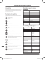
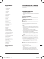
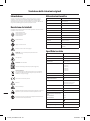
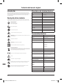
Technische afkortingen & symbolen
Specicaties
Modelnr.: TMNRTR
Spanning: 220-240 V, 50/60 Hz
Vermogen: 880 W
Onbelaste snelheid: 11.500-31.000 min-1
6 snelheidsinstellingen (1-6): 1) 11.500 min-1
2) 16.500 min-1
3) 21.000 min-1
4) 25.000 min-1
5) 29.000 min-1
6) 31.000 min-1
Kragen: 1/4” en 8 mm
Max. freesdiameter: 30 mm
Max. freesschacht: 8 mm
Insteekdiepte instelling: 1) Vrije insteek
2) Tafelhoogteschroef
3) Microschroef
Insteekbereik: 0-40 mm
Bereik parallelgeleiding: 0-130 mm
Diametert geleidingstaaf: 8 mm
Stofafvoeropening:
Inwendig:
Uitwendig:
35 mm
40 mm
Isolatieklasse:
Snoerlengte: 3 m
Binnendringingsbescherming: IP20
Draag oorbescherming
Draag oogbescherming
Draag ademhalingsbescherming
Draag hoofdbescherming
Draag handbescherming
Lees de gebruikshandleiding
NIET gebruiken in de regen of in een vochtige omgeving!
WAARSCHUWING: Bewegende delen kunnen knel- en snijverwondingen
veroorzaken.
Toxische dampen of gassen!
WAARSCHUWING: Scherpe bladen of tanden!
Klasse II constructie (dubbel geïsoleerd voor bijkomende bescherming)
Milieubescherming
Elektrische producten mogen niet met het normale huisvuil worden weggegooid.
Gelieve te recycleren indien deze mogelijkheid bestaat. Vraag de plaatselijke
autoriteiten of de verkoper om advies betreffende de recyclagemogelijkheden.
Voldoet aan de van kracht zijnde wetgeving en veiligheidsnormen
Opgepast!
Let op: terugslaggevaar!
Koppel steeds los van de voeding wanneer u accessoires aanpast of vervangt, wanneer
u schoonmaakwerkzaamheden of onderhoudswerkzaamheden uitvoert, en wanneer
het gereedschap niet gebruikt wordt!
Raak de bladen niet aan alvorens het gereedschap is losgekoppeld van de voeding en
alvorens de bladen volledig tot stilstand zijn gekomen
Beschrijving van de symbolen
Op het gegevensplaatje van uw gereedschap kunnen zich symbolen bevinden. Deze
vertegenwoordigen belangrijke productinformatie en gebruiksinstructies.
Inleiding
Hartelijk dank voor de aankoop van dit Triton-product. Deze handleiding omvat informatie die
nodig is voor een veilig en efciënt gebruik van dit product. Dit product is in het bezit van unieke
kenmerken en, zelfs indien u bekend bent met gelijkaardige producten, is het nodig om deze
handleiding aandachtig door te lezen om er zeker van te zijn dat u de instructies volledig begrijpt.
Zorg ervoor dat alle gebruikers van het product deze handleiding volledig gelezen en begrepen
hebben.
Vertaling van de originele instructies
VSpanning
~, AC Wisselstroom
A, mA Ampere, milli-Amp
n0Onbelaste snelheid
nNominale snelheid
°Graden
ØDiameter
Hz Hertz
W, kW Watt, kilowatt
/min or min-1 Bewerkingen per minuut
dB(A) Geluidsniveau decibel (A-gewogen)
m/s2Meter per seconde² (trillingsmagnitude)
817698_OwnerManual.indd 20817698_OwnerManual.indd 20 26/08/2022 15:0526/08/2022 15:05
Strona się ładuje...
Strona się ładuje...
Strona się ładuje...
Strona się ładuje...
Strona się ładuje...
Strona się ładuje...
Strona się ładuje...
Strona się ładuje...
Strona się ładuje...
Strona się ładuje...
Strona się ładuje...
Strona się ładuje...
Strona się ładuje...
Strona się ładuje...
Strona się ładuje...
Strona się ładuje...
Strona się ładuje...
Strona się ładuje...
Strona się ładuje...
Strona się ładuje...
Strona się ładuje...
Strona się ładuje...
Strona się ładuje...
Strona się ładuje...
Strona się ładuje...
Strona się ładuje...
Strona się ładuje...
Strona się ładuje...
Strona się ładuje...
Strona się ładuje...
Strona się ładuje...
Strona się ładuje...
Strona się ładuje...
Strona się ładuje...
Strona się ładuje...
Strona się ładuje...
Strona się ładuje...
Strona się ładuje...
Strona się ładuje...
Strona się ładuje...
Strona się ładuje...
Strona się ładuje...
Strona się ładuje...
Strona się ładuje...
Strona się ładuje...
Strona się ładuje...
Strona się ładuje...
Strona się ładuje...
Strona się ładuje...
Strona się ładuje...
Strona się ładuje...
Strona się ładuje...
Strona się ładuje...
Strona się ładuje...
Strona się ładuje...
Strona się ładuje...
Strona się ładuje...
Strona się ładuje...
Strona się ładuje...
Strona się ładuje...
Strona się ładuje...
Strona się ładuje...
Strona się ładuje...
Strona się ładuje...
Strona się ładuje...
Strona się ładuje...
Strona się ładuje...
Strona się ładuje...
-
 1
1
-
 2
2
-
 3
3
-
 4
4
-
 5
5
-
 6
6
-
 7
7
-
 8
8
-
 9
9
-
 10
10
-
 11
11
-
 12
12
-
 13
13
-
 14
14
-
 15
15
-
 16
16
-
 17
17
-
 18
18
-
 19
19
-
 20
20
-
 21
21
-
 22
22
-
 23
23
-
 24
24
-
 25
25
-
 26
26
-
 27
27
-
 28
28
-
 29
29
-
 30
30
-
 31
31
-
 32
32
-
 33
33
-
 34
34
-
 35
35
-
 36
36
-
 37
37
-
 38
38
-
 39
39
-
 40
40
-
 41
41
-
 42
42
-
 43
43
-
 44
44
-
 45
45
-
 46
46
-
 47
47
-
 48
48
-
 49
49
-
 50
50
-
 51
51
-
 52
52
-
 53
53
-
 54
54
-
 55
55
-
 56
56
-
 57
57
-
 58
58
-
 59
59
-
 60
60
-
 61
61
-
 62
62
-
 63
63
-
 64
64
-
 65
65
-
 66
66
-
 67
67
-
 68
68
-
 69
69
-
 70
70
-
 71
71
-
 72
72
-
 73
73
-
 74
74
-
 75
75
-
 76
76
-
 77
77
-
 78
78
-
 79
79
-
 80
80
-
 81
81
-
 82
82
-
 83
83
-
 84
84
-
 85
85
-
 86
86
-
 87
87
-
 88
88


Triton 880W Trimmer Router 1/4 Inch/ 8mm Instrukcja obsługi
- Typ
- Instrukcja obsługi
w innych językach
- español: Triton 880W Trimmer Router 1/4 Inch/ 8mm Manual de usuario
- italiano: Triton 880W Trimmer Router 1/4 Inch/ 8mm Manuale utente
- Deutsch: Triton 880W Trimmer Router 1/4 Inch/ 8mm Benutzerhandbuch
- português: Triton 880W Trimmer Router 1/4 Inch/ 8mm Manual do usuário
- français: Triton 880W Trimmer Router 1/4 Inch/ 8mm Manuel utilisateur
- English: Triton 880W Trimmer Router 1/4 Inch/ 8mm User manual
- русский: Triton 880W Trimmer Router 1/4 Inch/ 8mm Руководство пользователя
- Nederlands: Triton 880W Trimmer Router 1/4 Inch/ 8mm Handleiding