
DQOR® SERIES
2-WAY PASSIVE INDOOR/OUTDOOR INSTALLATION LOUDSPEAKER
LDDQOR3(B/W), LDDQOR5(B/W), LDDQOR8(B/W)
LDDQOR3T(B/W),LDDQOR5T(B/W),LDDQOR8T(B/W)
USER´S MANUAL
BEDIENUNGSANLEITUNG
MANUEL D’UTILISATION
MANUAL DE USUARIO
INSTRUKCJA OBSŁUGI
MANUALE D’USO

CONTENTS / INHALTSVERZEICHNIS / SOMMAIRE / CONTENIDO / SPIS TREŚCI / SOMMARIO
ENGLISH
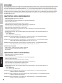
SAFETY INFORMATION 3
INTRODUCTION 5
FEATURES - MODELS WITH TRANSFORMER 5
FEATURES - LOW-IMPEDANCE MODELS 5
MEASUREMENTS (MM) 6
WALL MOUNTING PLATE 7
WALL MOUNTING 7
MODELS WITH TRANSFORMER 9
OPTIONAL ACCESSORY 9
TECHNICAL DATA 10
MANUFACTURER´S DECLARATIONS 13
DEUTSCH
SICHERHEITSHINWEISE 14
EINFÜHRUNG 16
EIGENSCHAFTEN - MODELLE MIT TRANSFORMATOR 16
EIGENSCHAFTEN - NIEDEROHMIGE MODELLE 16
ABMESSUNGEN (MM) 17
WANDMONTAGEPLATTE 18
WANDMONTAGE 18
MODELLE MIT TRANSFORMATOR 20
OPTIONALES ZUBEHÖR 20
TECHNISCHE DATEN 21
HERSTELLERERKLÄRUNGEN 24
FRANÇAIS
INFORMATIONS DE SÉCURITÉ 25
INTRODUCTION 27
CARACTÉRISTIQUES: MODÈLES AVEC TRANSFORMATEUR 27
CARACTÉRISTIQUES: MODÈLES À BASSE IMPÉDANCE 27
DIMENSIONS (MM) 28
SUPPORT DE MONTAGE MURAL 29
MONTAGE MURAL 29
MODÈLES AVEC TRANSFORMATEUR 31
ACCESSOIRES EN OPTION 31
CARACTÉRISTIQUES TECHNIQUES 32
DÉCLARATIONS DU FABRICANT 35
ESPAÑOL
INFORMACIÓN DE SEGURIDAD 36
INTRODUCCIÓN 38
CARACTERISTICAS: MODELOS CON TRANSFORMADOR 38
CARACTERISTICAS: MODELOS DE BAJA IMPEDANCIA 38
MEDIDAS (MM) 39
PLACA EMPOTRADA 40
MONTAJE EN LA PARED 40
MODELOS CON TRANSFORMADOR 42
ACCESORIOS OPCIONALES 42
DATOS TÉCNICOS 43
DECLARACIONES DEL FABRICANTE 46
POLSKI
INFORMACJE DOTYCZĄCE BEZPIECZEŃSTWA 47
WSTĘP 49
WŁAŚCIWOŚCI – MODELE ZTRANSFORMATOREM 49
WŁAŚCIWOŚCI – MODELE ONISKIEJ IMPEDANCJI 49
WYMIARY (MM) 50
UCHWYT ŚCIENNY 51
MONTAŻ NAŚCIENNY 51
MODELE ZTRANSFORMATOREM 53
AKCESORIA OPCJONALNE 53
DANE TECHNICZNE 54
OŚWIADCZENIA PRODUCENTA 57
ITALIANO
INFORMAZIONI SULLA SICUREZZA 58
INTRODUZIONE 60
CARATTERISTICHE: MODELLI CON TRASFORMATORE 60
CARATTERISTICHE: MODELLI A BASSA IMPEDENZA 60
MISURE (MM) 61
PIASTRA DI MONTAGGIO A PARETE 62
MONTAGGIO A PARETE 62
MODELLI CON TRASFORMATORE 64
ACCESSORIO OPZIONALE 64
DATI TECNICI 65
DICHIARAZIONI DEL PRODUTTORE 68

3
ENGLISH
YOU‘VE MADE THE RIGHT CHOICE!
We have designed this product to operate reliably over many years. LD Systems stands for this with its name and many years of experience as
a manufacturer of high-quality audio products. Please read this User‘s Manual carefully, so that you can begin making optimum use of your LD
Systems product quickly.
You can nd more information about LD-SYSTEMS at our Internet site WWW.LD-SYSTEMS.COM
SAFETY INFORMATION
1. Please read these instructions carefully.
2. Keep all information and instructions in a safe place.
3. Follow the instructions.
4. Observe all safety warnings. Never remove safety warnings or other information from the equipment.
5. Use the equipment only in the intended manner and for the intended purpose.
6. Use only sufficiently stable and compatible stands and/or mounts (for fixed installations). Make certain that wall mounts are properly installed
and secured. Make certain that the equipment is installed securely and cannot fall down.
7. During installation, observ e the applicable safety regulations for your country.
8. Never install and operate the equipment near radiators, heat registers, ovens or other sources of heat. Make certain that the equipment is
always installed so that is cooled sufficiently and cannot overheat.
9. Never place sources of ignition, e.g., burning candles, on the equipment.
10. Ventilation slits must not be blocked.
11. Keep a minimum distance of 20 cm around and above the device.
12. Do not use this equipment in the immediate vicinity of water (does not apply to special outdoor equipment - in this case, observe the special
instructions noted below. Do not expose this equipment to flammable materials, fluids or gases. Avoid direct sunlight!
13. Make certain that dripping or splashed water cannot enter the equipment. Do not place containers filled with liquids, such as vases or drinking
vessels, on the equipment.
14. Make certain that objects cannot fall into the device.
15. Use this equipment only with the accessories recommended and intended by the manufacturer.
16. Do not open or modify this equipment.
17. After connecting the equipment, check all cables in order to prevent damage or accidents, e.g., due to tripping hazards.
18. During transport, make certain that the equipment cannot fall down and possibly cause property damage and personal injuries.
19.
If your equipment is no longer functioning properly, if fluids or objects have gotten inside the equipment or if it has been damaged in anot her
way, switch it off immediately and unplug it from the mains outlet (if it is a powered device). This equipment may only be repaired by authorized,
qualified personnel.
20. Clean the equipment using a dry cloth.
21. Comply with all applicable disposal laws in your country. During disposal of packaging, please separate plastic and paper/cardboard.
22. Plastic bags must be kept out of reach of children.
23. Please note that changes or modifications not expressly approved by the party responsible for compliance could void the user´s authority to
operate the equipment.
FOR EQUIPMENT THAT CONNECTS TO THE POWER MAINS
24. CAUTION: If the power cord of the device is equipped with an earthing contact, then it must be connected to an outlet with a protective ground.
Never deactivate the protective ground of a power cord.
25. If the equipment has been exposed to strong fluctuations in temperature (for example, after transport), do not switch it on immediately.
Moisture and condensation could damage the equipment. Do not switch on the equipment until it has reached room temperature.
26. Before connecting the equipment to the power outlet, first verify that the mains voltage and frequency match the values specified on the
equipment. If the equipment has a voltage selection switch, connect the equipment to the power outlet only if the equipment values and the
mains power values match. If the included power cord or power adapter does not fit in your wall outlet, contact your electrician.
27. Do not step on the power cord. Make certain that the power cable does not become kinked, especially at the mains outlet and/or power adapter
and the equipment connector.
28.
When connecting the equipment, make certain that the power cord or power adapter is always freely accessible. Always disconnect the equipment
from the power supply if the equipment is not in use or if you want to clean the equipment. Always unplug the power cord and power adapter from
the power outlet at the plug or adapter and not by pulling on the cord. Never touch the power cord and power adapter with wet hands.
29.
Whenever possible, avoid switching the equipment on and off in quick succession because otherwise this can shorten the useful life of the equipment.
30. IMPORTANT INFORMATION: Replace fuses only with fuses of the same type and rating. If a fuse blows repeatedly, please contact an authorised
service centre.
31. To disconnect the equipment from the power mains completely, unplug the power cord or power adapter from the power outlet.
32. If your device is equipped with a Volex power connector, the mating Volex equipment connector must be unlocked before it can be removed.
However, this also means that the equipment can slide and fall down if the power cable is pulled, which can lead to personal injuries and/or
other damage. For this reason, always be careful when laying cables.
33. Unplug the power cord and power adapter from the power outlet if there is a risk of a lightning strike or before extended periods of disuse.
34. The appliance is not to be used by persons (including children) with reduced physical, sensory or mental capabilities, or lack of experience
andknowledge.
35. Children must be instructed not to play with the device.
36. If the power cord of the device is damaged, do not use the device. The power cord must be replaced by an adequate cable or assembly from an
authorized service center.
DEUTSCH ENGLISHFRANÇAIS
ESPAÑOLITALIANO POLSKI

4
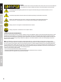
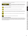
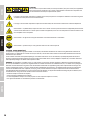
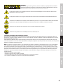
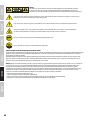
CAUTION:
To reduce the risk of electric shock, do not remove cover (or back). There are no user serviceable parts
inside. Maintenance and repairs should be exclusively carried out by qualified service personnel.
The warning triangle with lightning symbol indicates dangerous uninsulated voltage inside the unit, which may cause an
electricalshock.
The warning triangle with exclamation mark indicates important operating and maintenance instructions.
Warning! This symbol indicates a hot surface. Certain parts of the housing can become hot during operation.
After use, wait for a cool-down period of at least 10 minutes before handling or transporting the device.
Warning! This device is designed for use below 2000 metres in altitude.
Warning! This product is not intended for use in tropical climates.
CAUTION! HIGH VOLUMES IN AUDIO PRODUCTS!
This device is meant for professional use. Therefore, commercial use of this equipment is subject to the respectively applicable national accident
prevention rules and regulations. As a manufacturer, Adam Hall is obligated to notify you formally about the existence of potential health risks.
Hearing damage due to high volume and prolonged exposure: When in use, this product is capable of producing high sound-pressure levels (SPL)
that can lead to irreversible hearing damage in performers, employees, and audience members. For this reason, avoid prolonged exposure to
volumes in excess of 90 dB.
NOTE: This equipment has been tested and found to comply with the limits for a Class B digital device, pursuant to Part 15 of the FCC Rules.
Theselimits are designed to provide reasonable protection against harmful interference in a residential installation. This equipment generates,
uses and can radiate radio frequency energy and, if not installed and used in accordance with the instructions, may cause harmful interference
to radio communications. However, there is no guarantee that interference will not occur in a particular installation. If this equipment does cause
harmful interference to radio or television reception, which can be determined by turning the equipment off and on, the user is encouraged to
tryto correct the interference by one or more of the following measures:
– Reorient or relocate the receiving antenna.
– Increase the separation between the equipment and receiver.
– Connect the equipment into an outlet on a circuit different from that to which the receiver is connected.
– Consult the dealer or an experienced radio/TV technician for help.
DEUTSCHENGLISH
ITALIANO
POLSKI
ESPAÑOL
FRANÇAIS

5
INTRODUCTION
LD Systems presents a new series of installation speakers for indoors and outdoors. The 2-way systems in the new dynamic LD Systems design
are available as a low-impedance version (8 Ohm) and as a high-impedance version with a switch for the different transformers taps in 70 V or
100 V applications. The speakers are available in sizes 3", 5.25" and 8". For flexible integration into various indoor and outdoor sound systems, the
speakers have an integrated wall bracket and a practical slide and lock mechanism. Thanks to the integrated connection panel, the speakers can
also be used in visually demanding environments without visible cable paths. In addition, the 27° tilt and the 45° swivel mechanism enables exact
positioning for precise sound coverage. The new outdoor speakers are available in black and white.
FEATURES - MODELS WITH TRANSFORMER
• New dynamic LD Systems speaker design
• 2-way speaker system
• Integrated wall bracket with lock mechanism and speaker connections
• Suitable for use indoors and outdoors
• Aluminum grille for best corrosion protection
• Vertical and horizontal orientation possible, with 27° tilt and 45° pan angle
• BEM-optimized waveguide for constant directivity
• Wide, horizontal beam angle of 120° and vertical beam angle of 80°
• 3-position input select switch (16Ω / 70V / 100V) and switch for the transformer taps
• Very low transformer saturation
• Available in black (RAL 9005 = item number ending B) and white (RAL 9010 = item number ending W)
• Protection type
IP65 = LDDQOR3T (B/W)
IP55 = LDDQOR5T (B/W) & LDDQOR8T (B/W)
LDDQOR3T (B/W) - 2-way speaker system with 3“ woofer and 1“ titanium tweeter with FerroFluid™ cooling.
30W @ 16 Ohm, transformer taps 30W - 6W - 3W – 1.5W
LDDQOR5T (B/W) - 2-way speaker system with 5.25“ woofer and 1“ titanium tweeter with FerroFluid™ cooling.
70W @ 16 Ohm, transformer taps 70W - 30W - 15W - 7.5W - 3W
LDDQOR8T (B/W) - 2-way speaker system with 8“ woofer and 1“ titanium tweeter with FerroFluid™ cooling.
120W @ 16 Ohm, transformer taps 120 W - 70W - 30W - 15W - 7.5W - 3W
PACKAGING CONTENT
• DQOR3T and DQOR5T - 1 pair of speakers / DQOR8T - 1 speaker
• Hex key for the safety screw of the wall bracket
• User manual
FEATURES - LOW-IMPEDANCE MODELS
• New dynamic LD Systems speaker design
• 2-way speaker system
• Integrated wall bracket with lock mechanism and speaker connections
• Suitable for use indoors and outdoors
• Aluminum grille for best corrosion protection
• Vertical and horizontal orientation possible, with 27° tilt and 45° pan angle
• BEM-optimized waveguide for constant directivity
• Wide, horizontal beam angle of 120° and vertical beam angle of 80°
• Available in black (RAL 9005 = item number ending B) and white (RAL 9010 = item number ending W)
• Protection type
IP65 = LDDQOR3 (B/W)
IP55 = LDDQOR5 (B/W) & LDDQOR8 (B/W)
LDDQOR3 (B/W) - 2-way speaker system with 3“ woofer and 1“ titanium tweeter with FerroFluid™ cooling.
30W power rating 8 Ohm impedance
LDDQOR5 (B/W) - 2-way speaker system with 5.25“ deep woofer and 1“ titanium tweeter with FerroFluid™ cooling.
70W power rating 8 Ohm impedance
LDDQOR8 (B/W) - 2-way speaker system with 8“ woofer and 1“ titanium tweeter with FerroFluid™ cooling.
120W power rating 8 Ohm impedance
DEUTSCH ENGLISHFRANÇAIS
ESPAÑOLITALIANO POLSKI

6
PACKAGING CONTENT
• DQOR3 and DQOR5 - 1 pair of speakers / DQOR8 - 1 speaker
• Hex key for the safety screw of the wall bracket
• User manual
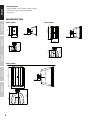
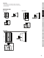
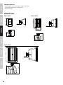
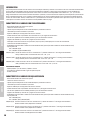
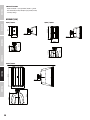
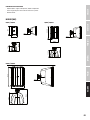
MEASUREMENTS (MM)
DQOR3 / DQOR3T DQOR5 / DQOR5T
DQOR8 / DQOR8T
DESIGNED AND ENGINEERED IN GERMANY. Assembled in PRC
LD Systems
®
is a registered brand of the Adam Hall Group.
Adam-Hall-Str. 1 · 61267 Neu-Anspach · Germany
Adam Hall assumes no responsibility or liability for the correctness, accuracy and completeness of this drawing. | Adam Hall übernimmt keine Gewähr oder Haftung für die Richtigkeit, Genauigkeit und Vollständigkeit dieser Zeichnung.
Scale 1:5
V1
Art No. XXX
DQOR 3
28.04.2020
180
114,6
180,8
111,6
54,7
DESIGNED AND ENGINEERED IN GERMANY. Assembled in PRC
LD Systems
®
is a registered brand of the Adam Hall Group.
Adam-Hall-Str. 1 · 61267 Neu-Anspach · Germany
Adam Hall assumes no responsibility or liability for the correctness, accuracy and completeness of this drawing. | Adam Hall übernimmt keine Gewähr oder Haftung für die Richtigkeit, Genauigkeit und Vollständigkeit dieser Zeichnung.
Art No. XXX
V1
28.04.2020
Scale 1:5
DQOR 5
148,3
215,3
156,7
253,8
54,7
DESIGNED AND ENGINEERED IN GERMANY. Assembled in PRC
LD Systems
®
is a registered brand of the Adam Hall Group.
Adam-Hall-Str. 1 · 61267 Neu-Anspach · Germany
Adam Hall assumes no responsibility or liability for the correctness, accuracy and completeness of this drawing. | Adam Hall übernimmt keine Gewähr oder Haftung für die Richtigkeit, Genauigkeit und Vollständigkeit dieser Zeichnung.
255,8
413,9
54,7
Scale 1:5
V1
Art No. XXX
28.04.2020
DQOR 8
316,4
247,3
DEUTSCHENGLISH
ITALIANO
POLSKI
ESPAÑOL
FRANÇAIS

7
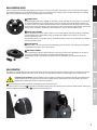
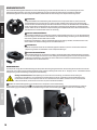
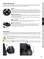
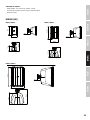
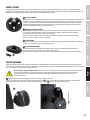
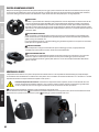
WALL MOUNTING PLATE
There are 4 holes in the round wall mounting plate for securing it to a wall. Please note that countersunk screws are required to secure the plate
and ensure that their flat heads are flush with the plate (screws are not included in the packaging content). The wall mounting plate is equipped
with a 4-pole terminal block, sliding contacts and two openings for speaker cables.
1
TERMINAL BLOCK
4-pole terminal block with spring clamping for connecting a speaker cable with an up to 2.5 mm² cross-section and
for sending the amplifier signal to another speaker connected in parallel. Please note the markings directly over
the contacts for the correct polarity. Open the terminal contacts of the terminal block by sliding a small screwdriver
with a flat head into the small opening above the respective contact. Now insert the stripped speaker cable into the
terminal contact and pull the screwdriver out of the opening once again to close the terminal contact.
2
CENTRAL CABLE BUSHING
Central cable bushing for speaker cables installed in a wall. Carefully pull the cable coming from the wall through
the 2mm drill hole present in the rubber sealing. The drill hole in the rubber seal is stretched as a result and
therefore surrounds the cable.
When mounting outdoors: If the rubber sealing is torn when mounting, seal the tears and open points in the rubber
sealing using silicone sealant.
3
SLIDING CONTACTS
When the speaker is correctly connected to the wall mounting plate, the speaker signal coming from the amplifier
is transmitted via the sliding contacts to the speaker.
4
LOWER CABLE BUSHING
Lower cable bushing for speaker cables installed on a wall. In order to release the cable bushing, the sealing cap
made of plastic must be removed prior to attaching the wall mounting plate to a wall.
When mounting outdoors: Seal open points between cable and cable bushing after installation using silicone
sealant.
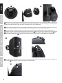
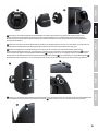
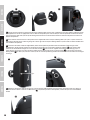
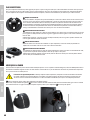
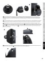
WALL MOUNTING
The speaker has a wall bracket with a practical lock mechanism. Thanks to the integrated connector panel, the speaker can also be used in visually
demanding environments without visible cables. The 27° tilt and 45° swivel mechanism enables exact positioning for precise sound coverage.
Important safety information: Overhead mounting requires experience, including the calculation of the limits for the workload, the
installation material used and regular safety tests of all installation materials and speakers. If you are not qualified, do not try to
perform the installation yourself, but use a professional company!
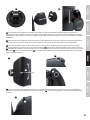
1
Prior to installing the speaker, remove the wall mounting plate from the wall bracket.
To do this, loosen the safety screw
A
in the dome-shaped union nut using the hex key included, turn the union nut counterclockwise from the wall
bracket and pull the wall mounting plate
B
downwards from the wall bracket.
1
2
33
4
1
A
B
DEUTSCH ENGLISHFRANÇAIS
ESPAÑOLITALIANO POLSKI

8
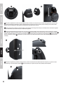
2
Firmly secure the wall mounting plate with the terminal block at the top using suitable screws on a wall sufficiently capable of supporting the
load. For speaker cables laid under plaster, the corresponding cable must be inserted through the central cable bushing prior to securing the wall
mounting plate. Now connect the speaker cables to the corresponding contacts of the terminal block.
3
Slide the speaker with the wall bracket from above onto the wall mounting plate in such a way that the contacts on the speaker slide into the
guide grooves of the sliding contacts of the wall mounting plate and the retaining hook engage into the corresponding recess.
4
Using the ball joint in the wall bracket, the speaker can be turned to the vertical or the horizontal position (turning in both directions by
maximum 180°). Then tilt and swivel the speaker into the desired beam direction
C
. Now fix the speaker by screwing the dome-shaped union nut
D
clockwise tightly onto the associated thread until the marking on the union nut matches either the marking on the retaining hook
E
or the
marking on the wall mounting plate
F
to ensure that the safety screw can also engage into one of the two through-holes in the collet.
5
Secure the ball joint and the dome-shaped union nut from moving by tightening the safety screw in the union nut clockwise using the hex key
that is included
G
. When you do this, make sure that the screw is fully countersunk.
2 3
D
C
E
F
4
5
G
DEUTSCHENGLISH
ITALIANO
POLSKI
ESPAÑOL
FRANÇAIS

9
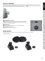
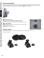
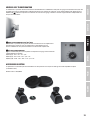
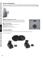
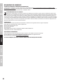
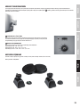
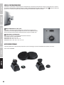
MODELS WITH TRANSFORMER
The 3-position switch for the operating mode and the switch for the transformer taps are below the wall bracket in a control section behind a
water-tight rubber covering in the models DQOR 3T(B/W), DQOR 5T(B/W) and DQOR 8T(B/W)
A
. Lift the rubber covering in order to carry out the
desired settings and seal the control compartment carefully again afterwards.
1
OPERATING MODE 16 Ω / 70V / 100V
3-position switch to adjust the installation speaker for 70V or 100V installation amplifiers
or amplifiers with low-impedance output (16 Ohm). Move the switch to the corresponding
position prior to connecting to the amplifier.
2
TRANSFORMER TAPS
Switch for selecting the desired transformer tap (as an example model DQOR5TW).
DQOR 3T(B/W): 30W – 6W – 3W – 1.5W
DQOR 5T(B/W): 70W – 30W – 15W – 7.5W – 3W
DQOR 8T(B/W): 120W – 70W – 30W – 15W – 7.5W – 3W
OPTIONAL ACCESSORY
Rubber coverings for the speaker connection and the wall mounting plate are optionally available (2 sets included).
Item number: LDDQORWMC
A
1
2
DEUTSCH ENGLISHFRANÇAIS
ESPAÑOLITALIANO POLSKI

10
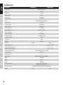
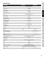
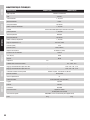
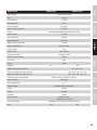
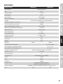
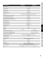
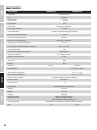
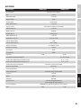
TECHNICAL DATA
Item number: LDDQOR3(B/W) LDDQOR3T(B/W)
Product type Installation speaker
Type Passive
Woofer size 3“, 76.2 mm
Woofer magnet Ferrite
Woofer brand Custom Made
Woofer voice coil 1“, 25.4 mm
Horn BEM-optimized CD waveguide
HF driver size 1“, 25.4 mm
HF driver magnet Neodymium
HF driver brand Custom Made
HF driver voice coil 1“, 25.4 mm
Beam angle (H x V) 120° x 80° (-6 dB)
Power rating (RMS) 30 W
Power rating (peak) 60 W (>200Hz)
Frequency response 85 - 20000 Hz (-10dB)
Crossover frequency 2200 Hz
SPL (1 W/1 m) 80 dB
Max. SPL 98 dB
Impedance 8 Ohm 16 Ohm
Input select switch – 70 V - 100 V - 16 Ohm
100V transformer power taps – 30 - 6 - 3 - 1.5W
70V transformer power taps – 30 - 6 - 3 - 1.5W
Speaker input connections 4-pole terminal block. Pitch 5.08mm
Housing material ABS plastic
IP protection class 65
Housing color White (RAL 9010) / black (RAL 9005)
Width 114.6 mm
Height 180 mm
Depth 180.8 mm
Included accessories Bracket for surface mounting
Allen key for the safety screw
Optional accessory LDDQORWMC (rubber covering set for wall bracket)
Weight 1.4 kg 2.1 kg
DEUTSCHENGLISH
ITALIANO
POLSKI
ESPAÑOL
FRANÇAIS

11
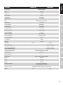
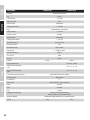
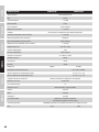
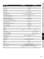
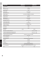
Item number: LDDQOR5(B/W) LDDQOR5T(B/W)
Product type Installation speaker
Type Passive
Woofer size 7“, 133 mm
Woofer magnet Ferrite
Woofer brand Custom Made
Woofer voice coil 1“, 25.4 mm
Horn BEM-optimized CD waveguide
HF driver size 1“, 25.4 mm
HF driver magnet Neodymium
HF driver brand Custom Made
HF driver voice coil 1“, 25.4 mm
Beam angle (H x V) 120° x 80° (-6 dB)
Power rating (RMS) 70 W
Power rating (peak) 140 W (>200Hz)
Frequency response 74 - 20000 Hz (-10dB)
Crossover frequency 1900 Hz
SPL (1 W/1 m) 84 dB
Max. SPL 105 dB
Impedance 8 Ohm 16 Ohm
Input select switch – 70 V - 100 V - 16 Ohm
100V transformer power taps – 70 - 30 - 15 - 7.5 - 3 W
70V transformer power taps – 70 - 30 - 15 - 7.5 - 3 W
Speaker input connections 4-pole terminal block. Pitch 5.08mm
Housing material ABS plastic
IP protection class 55
Housing color White (RAL 9010) / black (RAL 9005)
Width 156.7 mm
Height 253.8 mm
Depth 215.3 mm
Included accessories Bracket for surface mounting
Allen key for the safety screw
Optional accessory LDDQORWMC (rubber covering set for wall bracket)
Weight 2.7 kg 3.9 kg
DEUTSCH ENGLISHFRANÇAIS
ESPAÑOLITALIANO POLSKI

12
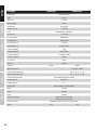
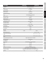
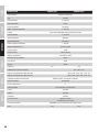
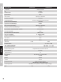
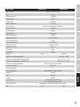
Item number: LDDQOR8(B/W) LDDQOR8T(B/W)
Product type Installation speaker
Type Passive
Woofer size 8“, 200 mm
Woofer magnet Ferrite
Woofer brand Custom Made
Woofer voice coil 2“, 50.8 mm
Horn BEM-optimized CD waveguide
HF driver size 2“, 50.8 mm
HF driver magnet Neodymium
HF driver brand Custom Made
HF driver voice coil 1“, 25.4 mm
Beam angle (H x V) 120° x 80° (-6 dB)
Power rating (RMS) 120 W
Power rating (peak) 240 W (>200Hz)
Frequency response 62 - 20000 Hz (-10dB)
Crossover frequency 1800 Hz
SPL (1 W/1 m) 88 dB
Max. SPL 109 dB
Impedance 8 Ohm 16 Ohm
Input select switch – 70 V - 100 V - 16 Ohm
100V transformer power taps – 120 - 70 - 30 - 15 - 7.5 - 3 W
70V transformer power taps – 120 - 70 - 30 - 15 - 7.5 - 3 W
Speaker input connections 4-pole terminal block. Pitch 5.08mm
Housing material ABS plastic
IP protection class 55
Housing color White (RAL 9010) / black (RAL 9005)
Width 255.8 mm
Height 413.9 mm
Depth 314.6 mm
Included accessories Bracket for surface mounting
Allen key for the safety screw
Optional accessory LDDQORWMC (rubber covering set for wall bracket)
Weight 5.2 kg 7.2 kg
DEUTSCHENGLISH
ITALIANO
POLSKI
ESPAÑOL
FRANÇAIS

13
MANUFACTURER´S DECLARATIONS
MANUFACTURER‘S WARRANTY & LIMITATIONS OF LIABILITY
You can find our current warranty conditions and limitations of liability at: https://cdn-shop.adamhall.com/media/pdf/MANUFACTURERS-DECLARATIONS_
LD_SYSTEMS.pdf To request warranty service for a product, please contact Adam Hall GmbH, Adam-Hall-Str. 1,
61267 Neu Anspach / Email: [email protected] / +49 (0)6081 / 9419-0.
CORRECT DISPOSAL OF THIS PRODUCT
(valid in the European Union and other European countries with a differentiated waste collection system)
This symbol on the product, or on its documents indicates that the device may not be treated as household waste. This is to avoid
environmental damage or personal injury due to uncontrolled waste disposal. Please dispose of this product separately from other waste and have
it recycled to promote sustainable economic activity. Household users should contact either the retailer where they purchased this product, or their
local government office, for details on where and how they can recycle this item in an environmentally friendly manner. Business users should
contact their supplier and check the terms and conditions of the purchase contract. This product should not be mixed with other commercial waste
for disposal.
FCC STATEMENT
1. This device complies with Part 15 of the FCC Rules. Operation is subject to the following two conditions:
(1) This device may not cause harmful interference, and
(2) This device must accept any interference received, including interference that may cause undesired operation
2. any Changes or modifications not expressly approved by the party responsible for compliance could void the user‘s authority to operate the equipment.
NOTE: This equipment has been tested and found to comply with the limits for a Class B digital device, pursuant to Part 15 of the FCC Rules.
These limits are designed to provide reasonable protection against harmful interference in a residential installation.
This equipment generates uses and can radiate radio frequency energy and, if not installed and used in accordance with the instructions, may
cause harmful interference to radio communications. However, there is no guarantee that interference will not occur in a particular installation.
If this equipment does cause harmful interference to radio or television reception, which can be determined by turning the equipment off and on,
the user is encouraged to try to correct the interference by one or more of the following measures:
Reorient or relocate the receiving antenna.
Increase the separation between the equipment and receiver.
Connect the equipment into an outlet on a circuit different from that to which the receiver is connected.
Consult the dealer or an experienced radio/TV technician for help.
FCC RADIATION EXPOSURE STATEMENT
This equipment complies with FCC radiation exposure limits set forth for an uncontrolled environment. This equipment should be installed and
operated with minimum distance 20cm between the radiator & your body
CE COMPLIANCE
Adam Hall GmbH states that this product meets the following guidelines (where applicable):
R&TTE (1999/5/EC) or RED (2014/53/EU) from June 2017
Low voltage directive (2014/35/EU)
EMV directive (2014/30/EU)
RoHS (2011/65/EU)
The complete declaration of conformity can be found at www.adamhall.com.
Furthermore, you may also direct your enquiry to [email protected].
EU DECLARATION OF CONFORMITY
Hereby, Adam Hall GmbH declares that this radio equipment type is in compliance with Directive 2014/53/EU.
The full text of the EU declaration of conformity is available at the following
internet address: www.adamhall.com/compliance/
Printing errors and mistakes, as well as technical or other changes are reserved!
DEUTSCH ENGLISHFRANÇAIS
ESPAÑOLITALIANO POLSKI

14
DEUTSCH
SIE HABEN DIE RICHTIGE WAHL GETROFFEN!
Dieses Gerät wurde unter hohen Qualitätsanforderungen entwickelt und gefertigt, um viele Jahre einen reibungslosen Betrieb zu gewährleisten.
Dafür steht LD Systems mit seinem Namen und der langjährigen Erfahrung als Hersteller hochwertiger Audioprodukte. Bitte lesen Sie diese
Bedienungsanleitung sorgfältig, damit Sie Ihr neues Produkt von LD Systems schnell optimal einsetzen können.
Mehr Informationen zu LD SYSTEMS finden Sie auf unserer Internetseite WWW.LD-SYSTEMS.COM
SICHERHEITSHINWEISE
1. Lesen Sie diese Anleitung bitte sorgfältig durch.
2. Bewahren Sie alle Informationen und Anleitungen an einem sicheren Ort auf.
3. Befolgen Sie die Anweisungen.
4. Beachten Sie alle Warnhinweise. Entfernen Sie keine Sicherheitshinweise oder andere Informationen vom Gerät.
5. Verwenden Sie das Gerät nur in der vorgesehenen Art und Weise.
6. Verwenden Sie ausschließlich stabile und passende Stative bzw. Befestigungen (bei Festinstallationen).
Stellen Sie sicher, dass Wandhalterungen
ordnungsgemäß installiert und gesichert sind. Stellen Sie sicher, dass das Gerät sicher installiert ist und nicht herunterfallen kann.
7. Beachten Sie bei der Installation die für Ihr Land geltenden Sicherheitsvorschriften.
8. Installieren und betreiben Sie das Gerät nicht in der Nähe von Heizkörpern, Wärmespeichern, Öfen oder sonstigen Wärmequellen.
Sorgen Sie dafür, dass das Gerät immer so installiert ist, dass es ausreichend gekühlt wird und nicht überhitzen kann.
9. Platzieren Sie keine Zündquellen wie z.B. brennende Kerzen auf dem Gerät.
10. Lüftungsschlitze dürfen nicht blockiert werden.
11. Halten Sie einen Mindestabstand von 20 cm seitlich und oberhalb des Geräts ein.
12. Betreiben Sie das Gerät nicht in unmittelbarer Nähe von Wasser. Bringen Sie das Gerät nicht mit brennbaren Materialien, Flüssigkeiten oder Gasen in
Berührung. Direkte Sonneneinstrahlung vermeiden!
13. Sorgen Sie dafür, dass kein Tropf- oder Spritzwasser in das Gerät eindringen kann. Stellen Sie keine mit Flüssigkeit gefüllten Behältnisse wie Vasen
oder Trinkgefäße auf das Gerät.
14. Sorgen Sie dafür, dass keine Gegenstände in das Gerät fallen können.
15. Betreiben Sie das Gerät nur mit dem vom Hersteller empfohlenen und vorgesehenen Zubehör.
16. Öffnen Sie das Gerät nicht und verändern Sie es nicht.
17. Überprüfen Sie nach dem Anschluss des Geräts alle Kabelwege, um Schäden oder Unfälle, z. B. durch Stolperfallen zu vermeiden.
18. Achten Sie beim Transport darauf, dass das Gerät nicht herunterfallen und dabei möglicherweise Sach- und Personenschäden verursachen kann.
19. Wenn Ihr Gerät nicht mehr ordnungsgemäß funktioniert, Flüssigkeiten oder Gegenstände in das Geräteinnere gelangt sind, oder das Gerät
anderweitig beschädigt wurde, schalten Sie es sofort aus und trennen es von der Netzsteckdose (sofern es sich um ein aktives Gerät handelt).
DiesesGerät darf nur von autorisiertem Fachpersonal repariert werden.
20. Verwenden Sie zur Reinigung des Geräts ein trockenes Tuch.
21. Beachten Sie alle in Ihrem Land geltenden Entsorgungsgesetze. Trennen Sie bei der Entsorgung der Verpackung bitte Kunststoff und Papier bzw.
Kartonagen voneinander.
22. Kunststoffbeutel müssen außer Reichweite von Kindern aufbewahrt werden.
23. Sämtliche vom Benutzer vorgenommenen Änderungen und Modifikationen, denen die für die Einhaltung der Richtlinien verantwortliche Partei nicht
ausdrücklich zugestimmt hat, können zum Entzug der Betriebserlaubnis für das Gerät führen.
BEI GERÄTEN MIT NETZANSCHLUSS
24. ACHTUNG: Wenn das Netzkabel des Geräts mit einem Schutzkontakt ausgestattet ist, muss es an einer Steckdose mit Schutzleiter angeschlossen
werden. Deaktivieren Sie niemals den Schutzleiter eines Netzkabels.
25. Schalten Sie das Gerät nicht sofort ein, wenn es starken Temperaturschwankungen ausgesetzt war (beispielsweise nach dem Transport).
Feuchtigkeit und Kondensat könnten das Gerät beschädigen. Schalten Sie das Gerät erst ein, wenn es Zimmertemperatur erreicht hat.
26. Bevor Sie das Gerät an die Steckdose anschließen, prüfen Sie zuerst, ob die Spannung und die Frequenz des Stromnetzes mit den auf dem Gerät
angegebenen Werten übereinstimmen. Verfügt das Gerät über einen Spannungswahlschalter, schließen Sie das Gerät nur an die Steckdose an, wenn
die Gerätewerte mit den Werten des Stromnetzes übereinstimmen. Wenn das mitgelieferte Netzkabel bzw. der mitgelieferte Netzadapter nicht in
Ihre Netzsteckdose passt, wenden Sie sich an Ihren Elektriker.
27. Treten Sie nicht auf das Netzkabel. Sorgen Sie dafür, dass spannungsführende Kabel speziell an der Netzbuchse bzw. am Netzadapter und der
Gerätebuchse nicht geknickt werden.
28. Achten Sie bei der Verkabelung des Geräts immer darauf, dass das Netzkabel bzw. der Netzadapter stets frei zugänglich ist. Trennen Sie das Gerät
stets von der Stromzuführung, wenn das Gerät nicht benutzt wird, oder Sie das Gerät reinigen möchten. Ziehen Sie Netzkabel und Netzadapter immer
am Stecker bzw. am Adapter und nicht am Kabel aus der Steckdose. Berühren Sie Netzkabel und Netzadapter niemals mit nassen Händen.
29. Schalten Sie das Gerät möglichst nicht schnell hintereinander ein und aus, da sonst die Lebensdauer des Geräts beeinträchtigt werden könnte.
30. WICHTIGER HINWEIS: Ersetzen Sie Sicherungen ausschließlich durch Sicherungen des gleichen Typs und Wertes. Sollte eine Sicherung wiederholt
auslösen, wenden Sie sich bitte an ein autorisiertes Servicezentrum.
31. Um das Gerät vollständig vom Stromnetz zu trennen, entfernen Sie das Netzkabel bzw. den Netzadapter aus der Steckdose.
32. Wenn Ihr Gerät mit einem verriegelbaren Netzanschluss bestückt ist, muss der passende Gerätestecker entsperrt werden, bevor er entfernt werden
kann. Das bedeutet aber auch, dass das Gerät durch ein Ziehen am Netzkabel verrutschen und herunterfallen kann, wodurch Personen verletzt
werden und/oder andere Schäden auftreten können. Verlegen Sie Ihre Kabel daher immer sorgfältig.
33. Entfernen Sie Netzkabel und Netzadapter aus der Steckdose bei Gefahr eines Blitzschlags oder wenn Sie das Gerät länger nicht verwenden.
34. Das Gerät darf nicht von Personen (einschließlich Kindern) mit eingeschränkten körperlichen, sensorischen oder geistigen Fähigkeiten oder
mangelnder Erfahrung und Kenntnis benutzt werden.
35. Kinder müssen angewiesen werden, nicht mit dem Gerät zu spielen.
DEUTSCHENGLISH
ITALIANO
POLSKI
ESPAÑOL
FRANÇAIS

15
36. Wenn das Netzkabel des Geräts beschädigt ist, darf das Gerät nicht verwendet werden. Das Netzkabel muss durch ein adäquates Kabel oder eine
spezielle Baugruppe von einem autorisierten Service-Center ersetzt werden.
ACHTUNG
Entfernen Sie niemals die Abdeckung, da sonst das Risiko eines elektrischen Schlages besteht.
ImInneren des Geräts befinden sich keine Teile, die vom Bediener repariert oder gewartet werden
können. Lassen Sie Wartung und Reparaturen ausschließlich von qualifiziertem Servicepersonal
durchführen.
Das gleichseitige Dreieck mit Blitzsymbol warnt vor nichtisolierten, gefährlichen Spannungen im Geräteinneren, die einen
elektrischen Schlag verursachen können.
Das gleichseitige Dreieck mit Ausrufungszeichen kennzeichnet wichtige Bedienungs- und Wartungshinweise.
Warnung! Dieses Symbol kennzeichnet heiße Oberflächen. Während des Betriebs können bestimmte Teile des Gehäuses heiß
werden. Berühren oder transportieren Sie das Gerät nach einem Einsatz erst nach einer Abkühlzeit von mindestens 10 Minuten.
Warnung! Dieses Gerät ist für eine Nutzung bis zu einer Höhe von maximal 2000 Metern über dem Meeresspiegel bestimmt.
Warnung! Dieses Gerät ist nicht für den Einsatz in tropischen Klimazonen bestimmt.
ACHTUNG HOHE LAUTSTÄRKEN BEI AUDIOPRODUKTEN!
Dieses Gerät ist für den professionellen Einsatz vorgesehen. Der kommerzielle Betrieb dieses Geräts unterliegt den jeweils gültigen nationalen
Vorschriften und Richtlinien zur Unfallverhütung. Als Hersteller ist Adam Hall gesetzlich verpflichtet, Sie ausdrücklich auf mögliche Gesundheitsrisiken
hinzuweisen. Gehörschäden durch hohe Lautstärken und Dauerbelastung: Bei der Verwendung dieses Produkts können hohe Schalldruckpegel (SPL)
erzeugt werden, die bei Künstlern, Mitarbeitern und Zuschauern zu irreparablen Gehörschäden führen können. Vermeiden Sie länger anhaltende
Belastung durch hohe Lautstärken über 90 dB.
DEUTSCH ENGLISHFRANÇAIS
ESPAÑOLITALIANO POLSKI

16
EINFÜHRUNG
LD Systems präsentiert eine neue Serie von Installationslautsprechern für den Außen- und Innenbereich. Die 2-Wege-Systeme im neuen dynamischen
LD Systems Design sind als niederohmige Version (8 Ohm) und als hochohmige Version mit Schalter für die unterschiedlichen Transformatorabgriffe
in 70V- bzw. 100V-Anwendungen erhältlich. Verfügbar sind die Lautsprecher in den Größen 3", 5,25" und 8". Für die flexible Integration in eine Vielzahl
von Innen- und Außenbeschallungssystemen verfügen die Lautsprecher über eine integrierte Wandhalterung sowie einen praktischen Schiebe- und
Verriegelungsmechanismus. Dank des integrierten Anschlussfelds können die Lautsprecher auch in optisch anspruchsvollen Umgebungen ohne
sichtbare Kabelwege eingesetzt werden. Darüber hinaus ermöglicht der 27° Neigungs- und der 45° Schwenkmechanismus eine genaue Positionierung
für eine präzise Schallabdeckung. Die neuen Outdoor Lautsprecher sind in Schwarz und Weiß erhältlich.
EIGENSCHAFTEN - MODELLE MIT TRANSFORMATOR
• Neues dynamisches LD Systems Lautsprecherdesign
• 2-Wege Lautsprechersystem
• Integrierte Wandhalterung mit Verriegelungsmechanismus und Lautsprecheranschlüssen
• Geeignet für Außen- und Innenanwendungen
• Aluminiumgitter für besten Korrosionsschutz
• Vertikale und horizontale Ausrichtung möglich, mit 27° Tilt und 45° Pan Winkel
• BEM-optimiertes Waveguide für konstante Richtcharakteristik
• Breiter horizontaler Abstrahlwinkel von 120° und vertikaler Abstrahlwinkel von 80°
• 3-fach Eingangswahlschalter (16Ω / 70V / 100V) und Schalter für die Transformatorabgriffe
• Sehr geringe Transformatorsättigung
• Erhältlich in Schwarz (RAL 9005 = Artikelnummerendung B) und Weiß (RAL 9010 = Artikelnummerendung W)
• Schutzart
IP65 = LDDQOR3T (B/W)
IP55 = LDDQOR5T (B/W) & LDDQOR8T (B/W)
LDDQOR3T (B/W) - 2-Wege Lautsprechersystem mit 3“ Tieftöner und 1“ Titan-Hochtöner mit FerroFluid™-Kühlung
30W @ 16 Ohm, Transformatorabgriffe 30W - 6W - 3W – 1,5W
LDDQOR5T (B/W) - 2-Wege Lautsprechersystem mit 5,25“ Tieftöner und 1“ Titan-Hochtöner mit FerroFluid™-Kühlung
70W @ 16 Ohm, Transformatorabgriffe 70W - 30W - 15W - 7,5W - 3W
LDDQOR8T (B/W) - 2-Wege Lautsprechersystem mit 8“ Tieftöner und 1“ Titan-Hochtöner mit FerroFluid™-Kühlung
120W @ 16 Ohm, Transformatorabgriffe 120 W - 70W - 30W - 15W - 7,5W - 3W
LIEFERUMFANG
• DQOR3T und DQOR5T - 1 Paar Lautsprecher / DQOR8T - 1 Lautsprecher
• Sechskantwerkzeug für die Sicherungsschraube der Wandhalterung
• Bedienungsanleitung
EIGENSCHAFTEN - NIEDEROHMIGE MODELLE
• Neues dynamisches LD Systems Lautsprecherdesign
• 2-Wege Lautsprechersystem
• Integrierte Wandhalterung mit Verriegelungsmechanismus und Lautsprecheranschlüssen
• Geeignet für Außen- und Innenanwendungen
• Aluminiumgitter für besten Korrosionsschutz
• Vertikale und horizontale Ausrichtung möglich, mit 27° Tilt und 45° Pan Winkel
• BEM-optimiertes Waveguide für konstante Richtcharakteristik
• Breiter horizontaler Abstrahlwinkel von 120° und vertikaler Abstrahlwinkel von 80°
• Erhältlich in Schwarz (RAL 9005 = Artikelnummerendung B) und Weiß (RAL 9010 = Artikelnummerendung W)
• Schutzart
IP65 = LDDQOR3T (B/W)
IP55 = LDDQOR5T (B/W) & LDDQOR8T (B/W)
LDDQOR3 (B/W) - 2-Wege Lautsprechersystem mit 3“ Tieftöner und 1“ Titan-Hochtöner mit FerroFluid™-Kühlung
30W Belastbarkeit, 8 Ohm Impedanz
LDDQOR5 (B/W) - 2-Wege Lautsprechersystem mit 5,25“ Tieftöner und 1“ Titan-Hochtöner mit FerroFluid™-Kühlung
70W Belastbarkeit, 8 Ohm Impedanz
LDDQOR8 (B/W) - 2-Wege Lautsprechersystem mit 8“ Tieftöner und 1“ Titan-Hochtöner mit FerroFluid™-Kühlung
120W Belastbarkeit, 8 Ohm Impedanz
DEUTSCHENGLISH
ITALIANO
POLSKI
ESPAÑOL
FRANÇAIS

17
LIEFERUMFANG
• DQOR3 und DQOR5 - 1 Paar Lautsprecher / DQOR8 - 1 Lautsprecher
• Sechskantwerkzeug für die Sicherungsschraube der Wandhalterung
• Bedienungsanleitung
ABMESSUNGEN (MM)
DQOR3 / DQOR3T DQOR5 / DQOR5T
DQOR8 / DQOR8T
DESIGNED AND ENGINEERED IN GERMANY. Assembled in PRC
LD Systems
®
is a registered brand of the Adam Hall Group.
Adam-Hall-Str. 1 · 61267 Neu-Anspach · Germany
Adam Hall assumes no responsibility or liability for the correctness, accuracy and completeness of this drawing. | Adam Hall übernimmt keine Gewähr oder Haftung für die Richtigkeit, Genauigkeit und Vollständigkeit dieser Zeichnung.
Scale 1:5
V1
Art No. XXX
DQOR 3
28.04.2020
180
114,6
180,8
111,6
54,7
DESIGNED AND ENGINEERED IN GERMANY. Assembled in PRC
LD Systems
®
is a registered brand of the Adam Hall Group.
Adam-Hall-Str. 1 · 61267 Neu-Anspach · Germany
Adam Hall assumes no responsibility or liability for the correctness, accuracy and completeness of this drawing. | Adam Hall übernimmt keine Gewähr oder Haftung für die Richtigkeit, Genauigkeit und Vollständigkeit dieser Zeichnung.
Art No. XXX
V1
28.04.2020
Scale 1:5
DQOR 5
148,3
215,3
156,7
253,8
54,7
DESIGNED AND ENGINEERED IN GERMANY. Assembled in PRC
LD Systems
®
is a registered brand of the Adam Hall Group.
Adam-Hall-Str. 1 · 61267 Neu-Anspach · Germany
Adam Hall assumes no responsibility or liability for the correctness, accuracy and completeness of this drawing. | Adam Hall übernimmt keine Gewähr oder Haftung für die Richtigkeit, Genauigkeit und Vollständigkeit dieser Zeichnung.
255,8
413,9
54,7
Scale 1:5
V1
Art No. XXX
28.04.2020
DQOR 8
316,4
247,3
DEUTSCH ENGLISHFRANÇAIS
ESPAÑOLITALIANO POLSKI

18
WANDMONTAGEPLATTE
In der runden Wandmontageplatte befinden sich 4 Löcher zur Befestigung an einer Wand. Bitte beachten Sie, dass zum Befestigen der Platte
Senkkopfschrauben erforderlich sind, deren flacher Kopf bündig mit der Platte abschließt (Schrauben nicht im Lieferumfang enthalten).
DieWandmontageplatte ist mit einem 4-poligen Klemmblock, Gleitkontakten und zwei Öffnungen für Lautsprecherkabel ausgestattet.
1
KLEMMBLOCK
4-poliger Klemmblock mit Federklemmung zum Anschließen eines Lautsprecherkabels bis 2,5mm² Querschnitt
und zum Weiterleiten des Verstärkersignals an weitere, parallel verkabelte Lautsprecher. Für die korrekte Polung
beachten Sie bitte die Kennzeichnungen direkt über den Kontakten. Öffnen Sie die Klemmkontakte des Klemmblocks,
indem Sie einen kleinen Schraubendreher mit flacher Klinge in die kleine Öffnung oberhalb des jeweiligen Kontakts
schieben. Führen Sie nun die abisolierte Lautsprecherleitung in den Klemmkontakt ein und ziehen zum Schließen des
Klemmkontakts den Schraubendreher wieder aus der Öffnung.
2
ZENTRALE KABELDURCHFÜHRUNG
Zentrale Kabeldurchführung für in einer Wand installierte Lautsprecherkabel. Ziehen Sie das aus der Wand kommende
Kabel vorsichtig durch die vorhandene 2mm Bohrung in der Gummiabdichtung. Die Bohrung in der Gummiabdichtung
wird dadurch gedehnt und umschließt somit das Kabel.
Bei Montage im Außenbereich: Sollte die Gummiabdichtung bei der Montage einreißen, verschließen Sie Risse und
offene Stellen in der Gummiabdichtung mit Hilfe von Silikon Dichtmasse.
3
GLEITKONTAKTE
Sobald der Lautsprecher korrekt mit der Wandmontageplatte verbunden ist, wird das vom Verstärker kommende
Lautsprechersignal über die Gleitkontakte an den Lautsprecher übertragen.
4
UNTERE KABELDURCHFÜHRUNG
Untere Kabeldurchführung für auf einer Wand installierte Lautsprecherkabel. Um die Kabeldurchführung freizugeben,
muss die Verschlusskappe aus Kunststoff vor dem Anbringen der Wandmontageplatte an einer Wand entfernt werden.
Bei Montage im Außenbereich: Verschließen Sie offene Stellen zwischen Kabel und Kabeldurchführung nach der
Installation mit Hilfe von Silikon Dichtmasse.
WANDMONTAGE
Der Lautsprecher verfügt über eine Wandhalterung mit einem praktischen Verriegelungsmechanismus. Dank des integrierten Anschlussfelds kann der
Lautsprecher auch in optisch anspruchsvollen Umgebungen ohne sichtbare Kabel eingesetzt werden. Der 27 ° Neigungs- und 45 ° Schwenkmechanismus
ermöglicht eine genaue Positionierung für eine präzise Schallabdeckung.
Wichtige Sicherheitshinweise: Überkopfmontage erfordert umfassende Erfahrung, einschließlich der Berechnung der
Grenzwerte für die Arbeitslast, des verwendeten Installationsmaterials und der regelmäßigen Sicherheitsüberprüfung aller
Installationsmaterialien und Lautsprecher. Wenn Sie diese Qualifikationen nicht haben, versuchen Sie nicht, eine Installation
selbstdurchzuführen, sondern nutzen Sie die Hilfe von professionellen Unternehmen.
1
Nehmen Sie die Wandmontageplatte vor der Installation des Lautsprechers von der Wandhalterung.
Lösen Sie hierfür die Sicherungsschraube
B
in der kuppelförmigen Überwurfmutter mit Hilfe des beiliegenden Sechskantwerkzeugs, drehen die
Überwurfmutter gegen den Uhrzeigersinn von der Wandhalterung und ziehen die Wandmontageplatte
B
nach unten von der Wandhalterung.
1
2
33
4
1
A
B
DEUTSCHENGLISH
ITALIANO
POLSKI
ESPAÑOL
FRANÇAIS

19
2
Befestigen Sie die Wandmontageplatte mit dem Klemmblock nach oben zeigend mit Hilfe von geeignetem Befestigungsmaterial sicher
an einer ausreichend tragfähigen Wand. Bei unter Putz verlegten Lautsprecherkabeln muss das entsprechende Kabel vor dem Befestigen der
Wandmontageplatte durch die zentrale Kabeldurchführung gesteckt werden. Verbinden Sie nun die Lautsprecherkabel mit den entsprechenden
Kontakten des Klemmblocks.
3
Schieben Sie den Lautsprecher mit der Wandhalterung von oben auf die Wandmontageplatte, in der Art, dass die Kontakte am Lautsprecher in die
Führungsnuten der Gleitkontakte der Wandmontageplatte gleiten und der Haltehaken in die entsprechende Aussparung greift.
4
Mit Hilfe des Kugelgelenks in der Wandhalterung kann der Lautsprecher in die vertikale oder die horizontale Position gedreht werden
(Drehunginbeide Richtungen maximal 180°). Dann neigen und schwenken Sie den Lautsprecher in die gewünschte Abstrahlrichtung
C
. Fixieren Sie
nun den Lautsprecher, indem Sie die kuppelförmige Überwurfmutter
D
im Uhrzeigersinn fest auf das zugehörige Gewinde schrauben, so weit, bis
die Markierung auf der Überwurfmutter entweder mit der Markierung auf dem Haltehaken
E
oder der Markierung auf der Wandmontageplatte
F
übereinstimmt, damit sichergestellt ist, dass die Sicherungsschraube auch in eines der beiden Durchgangslöcher in der Spannzange greifen kann.
5
Sichern Sie das Kugelgelenk und die kuppelförmige Überwurfmutter gegen Verstellen, indem Sie die Sicherungsschraube in der Überwurfmutter mit
Hilfe des beigelegten Sechskantwerkzeugs im Uhrzeigersinn festziehen
G
. Achten Sie dabei darauf, dass die Schraube vollständig versenkt ist.
2 3
D
C
E
F
4
5
G
DEUTSCH ENGLISHFRANÇAIS
ESPAÑOLITALIANO POLSKI

20
MODELLE MIT TRANSFORMATOR
Der 3-fach Schalter für die Betriebsart und der Schalter für die Transformatorabgriffe befinden sich bei den Modellen DQOR 3T(B/W), DQOR 5T(B/W) und
DQOR 8T(B/W) in einem Bedienfach hinter einer wasserdichten Gummiabdeckung
A
unterhalb der Wandhalterung. Heben Sie die Gummiabdeckung
an, um die gewünschten Einstellungen vorzunehmen und verschließen das Bedienfach danach wieder sorgfältig.
1
BETRIEBSART 16 Ω / 70V / 100V
3-Weg-Schalter zum Anpassen des Installationslautsprechers an 70V bzw. 100V
Installationsverstärker oder Verstärker mit niederohmigem Ausgang (16 Ohm).
Bringen Sie den Schalter vor dem Anschließen an den Verstärker in die entsprechende Position.
2
TRANSFORMATORABGRIFFE
Schalter zum Auswählen des gewünschten Transformatorabgriffs (im Beispiel Modell DQOR5TW).
DQOR 3T(B/W): 30W – 6W – 3W – 1.5W
DQOR 5T(B/W): 70W – 30W – 15W – 7.5W – 3W
DQOR 8T(B/W): 120W – 70W – 30W – 15W – 7,5W – 3W
OPTIONALES ZUBEHÖR
Gummiabdeckungen für den Lautsprecheranschluss und die Wandmontageplatte sind optional erhältlich (Inhalt 2 Sätze).
Artikelnummer: LDDQORWMC
A
1
2
DEUTSCHENGLISH
ITALIANO
POLSKI
ESPAÑOL
FRANÇAIS
Strona się ładuje...
Strona się ładuje...
Strona się ładuje...
Strona się ładuje...
Strona się ładuje...
Strona się ładuje...
Strona się ładuje...
Strona się ładuje...
Strona się ładuje...
Strona się ładuje...
Strona się ładuje...
Strona się ładuje...
Strona się ładuje...
Strona się ładuje...
Strona się ładuje...
Strona się ładuje...
Strona się ładuje...
Strona się ładuje...
Strona się ładuje...
Strona się ładuje...
Strona się ładuje...
Strona się ładuje...
Strona się ładuje...
Strona się ładuje...
Strona się ładuje...
Strona się ładuje...
Strona się ładuje...
Strona się ładuje...
Strona się ładuje...
Strona się ładuje...
Strona się ładuje...
Strona się ładuje...
Strona się ładuje...
Strona się ładuje...
Strona się ładuje...
Strona się ładuje...
Strona się ładuje...
Strona się ładuje...
Strona się ładuje...
Strona się ładuje...
Strona się ładuje...
Strona się ładuje...
Strona się ładuje...
Strona się ładuje...
Strona się ładuje...
Strona się ładuje...
Strona się ładuje...
Strona się ładuje...
Strona się ładuje...
Strona się ładuje...
Strona się ładuje...
Strona się ładuje...
-
 1
1
-
 2
2
-
 3
3
-
 4
4
-
 5
5
-
 6
6
-
 7
7
-
 8
8
-
 9
9
-
 10
10
-
 11
11
-
 12
12
-
 13
13
-
 14
14
-
 15
15
-
 16
16
-
 17
17
-
 18
18
-
 19
19
-
 20
20
-
 21
21
-
 22
22
-
 23
23
-
 24
24
-
 25
25
-
 26
26
-
 27
27
-
 28
28
-
 29
29
-
 30
30
-
 31
31
-
 32
32
-
 33
33
-
 34
34
-
 35
35
-
 36
36
-
 37
37
-
 38
38
-
 39
39
-
 40
40
-
 41
41
-
 42
42
-
 43
43
-
 44
44
-
 45
45
-
 46
46
-
 47
47
-
 48
48
-
 49
49
-
 50
50
-
 51
51
-
 52
52
-
 53
53
-
 54
54
-
 55
55
-
 56
56
-
 57
57
-
 58
58
-
 59
59
-
 60
60
-
 61
61
-
 62
62
-
 63
63
-
 64
64
-
 65
65
-
 66
66
-
 67
67
-
 68
68
-
 69
69
-
 70
70
-
 71
71
-
 72
72


w innych językach
Powiązane artykuły
-
LD Systems Maui i1 Indoor/Outdoor Column 8Ω/70-100 V Instrukcja obsługi
-
LD Systems Contractor CWMS 42 B Instrukcja obsługi
-
LD Stinger 8A G3 8" Powered Speaker Instrukcja obsługi
-
LD Systems SAT 442 G2 Instrukcja obsługi
-
LD LDEB82G3 Instrukcja obsługi
-
-
-
LD Systems Contractor CIWS 62 Instrukcja obsługi
-
LD Systems Contractor CFL 62 Instrukcja obsługi
-
LD Contractor CICS 52 100 V Instrukcja obsługi
Inne dokumenty
-
Morel MAXIMO ULTRA Instrukcja obsługi
-
Omnitronic 80710460 Karta katalogowa
-
AUKEY LC-A1 Instrukcja obsługi
-
Monacor IT-30 Karta katalogowa
-
 Pyle Pro PLMRTW25B Instrukcja obsługi
-
Focal ISU690 Instrukcja obsługi
-
Optimus BS-60BP Karta katalogowa
-
-
-
