Yamaha DTX530K Instrukcja obsługi
- Kategoria
- Instrumenty muzyczne
- Typ
- Instrukcja obsługi
Niniejsza instrukcja jest również odpowiednia dla

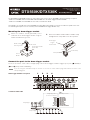
Connect the pads to the drum trigger module
Insert the 9-channel snake cable’s straight plugs into the drum trigger module’s trigger input jacks ([
q
SNARE] to
[
o
KICK/
!0
] and [HI-HAT CONTROL]).
If you are using the standard setup, the stickers on each of the snake cable’s plugs will indicate the name of the
corresponding pad.
Drum trigger module’s rear panel
9-channel snake cable
DTX560K/DTX530K
Assembly Manual
EN
Digital Musical Instruments Division
©2011 Yamaha Corporation
WZ78140 106YJ-A0
The DTX560K and DTX530K feature the same Drum units as those of the DTX700K, with the following exceptions:
- Unlike the DTX700K, both the DTX560K and DTX530K have the Drum Trigger Module DTX500.
- Unlike the DTX700K, the DTX530K has the TP65, instead of the XP70.
Accordingly, you should refer to the DTX700K Assembly Manual for details on how to assemble the pads to the rack.
The following description covers assembly of the DTX500 Drum Trigger Module only.
Mounting the drum trigger module
1.
Attach the module stand (provided) to the
underside of the drum trigger module using the
module stand fastening screws.
2.
Place the module stand inside the holder clamp
and tighten the clamp bolt to secure in position.
HH CON HI-HAT CRASH KICK SNARE TOM1 TOM2 TOM3 RIDE
Straight plugs
L-shaped plugs
Straight plug names
(as shown on stickers)
SNARE
TOM1
TOM2
TOM3
RIDE
CRASH
HI-HAT
KICK
HH CON
DTX500 jack names
1:
q
SNARE
2:
w
TOM1/
!0
3:
e
TOM2/
!1
4:
r
TOM3/
!2
5:
t
RIDE
6:
y
CRASH
7:
u
HI-HAT
8:
i
KICK/
o
9: HIHAT CONTROL
Module stand
fastening screws
Module stand
Drum trigger module
(back side)
Front of
Module
Insert
Drum trigger
module
+
module stand
Clamp bolt
Holder Clamp
1 2 3 4
5 6 7 8 9
NOTE
-
 1
1

Yamaha DTX530K Instrukcja obsługi
- Kategoria
- Instrumenty muzyczne
- Typ
- Instrukcja obsługi
- Niniejsza instrukcja jest również odpowiednia dla
w innych językach
- čeština: Yamaha DTX530K Uživatelský manuál
- español: Yamaha DTX530K Manual de usuario
- italiano: Yamaha DTX530K Manuale utente
- Deutsch: Yamaha DTX530K Benutzerhandbuch
- svenska: Yamaha DTX530K Användarmanual
- português: Yamaha DTX530K Manual do usuário
- français: Yamaha DTX530K Manuel utilisateur
- Türkçe: Yamaha DTX530K Kullanım kılavuzu
- English: Yamaha DTX530K User manual
- dansk: Yamaha DTX530K Brugermanual
- русский: Yamaha DTX530K Руководство пользователя
- Nederlands: Yamaha DTX530K Handleiding
- română: Yamaha DTX530K Manual de utilizare
Powiązane artykuły
-
Yamaha DTX RS500 Instrukcja obsługi
-
-
-
-
-
-
Yamaha DTX6K-X E-Drum Set Instrukcja obsługi
-
-
-