Yamaha Computer Drive AI8 Instrukcja obsługi
- Typ
- Instrukcja obsługi

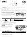
ANALOG IN
CH2B
B
SIGNAL
MIC/LINE INPUT CARD
MODEL LMY2-ML
B
SIGNAL
CH2A CH1B CH1A
When the indicator is lit in orange, channel B is selected.
When the indicator is turned off, channel A is selected.
The green LED lights up
at 34 dB before clipping.
ANALOG IN
CH4
SIGNAL
SIGNAL
AD CARD
MODEL LMY4-AD
SIGNAL
SIGNAL
CH3 CH2 CH1
The green LED lights up at 34 dB before clipping.
Input Actual Load For Use With
Input Level
Connector
Terminals Impedance Nominal
Nominal Max. Before Clip
CH 1-4 10 kΩ 600 Ω Lines +10 dB (2.45 V)* +24 dB (12.3 V)* XLR-3-31 type (Balanced)**
* 0 dB is referenced to 0.775 Vrms.
** 1=GND, 2=HOT, 3=COLD
AD Conversion: 24 bit linear +4 bit floating, 128 times oversampling.
I/O cards
for
ANALOG OUTPUT BOX
ANALOG INPUT BOX
MIC/LINE INPUT CARD LMY2-ML
AD CARD LMY4-AD
DA CARD LMY4-DA
T
hank you for choosing the Yamaha input card for the analog input box AI8, and the Yamaha output card for the analog
output box AO8.
Be sure to ask an authorized Yamaha service engineer to install the cards. Do not install the cards yourself.
The connecting screw also functions as the ground. Secure the screw tightly.
■ LMY2-ML
This is a two-channel analog input card. Set the input level in the range
of –68 dB to +10 dB.
You can install up to eight cards in the analog input box AI8.
Input
GAIN***
Actual Load For Use With
Input Level
Connector
Terminals Impedance Nominal
Nominal Max. Before Clip
CH1A, CH1B
–68 dB
3 kΩ
50-600 Ω Mics
–68 dB (309 µV)* –54 dB (1.55 mV)*
XLR-3-31 type
CH2A, CH2B
+10 dB
& 600 Ω Lines
+10 dB (2.45 V)* +24 dB (12.3 V)*
(Balanced)**
* 0 dB is referenced to 0.775 Vrms.
** 1=GND, 2=HOT, 3=COLD
*** The GAIN control level displayed on the CS1D.
+48VDC (phantom power) is individually supplied to each input connectors.
AD Conversion: 24 bit linear +4 bit floating, 128 times oversampling.
■ LMY4-AD
This is a four-channel analog input card.
You can install up to eight cards in the analog input box AI8.

For European Model
Purchaser/User Information specified in EN55103-1 and EN55103-2.
Conformed Environment: E1, E2, E3 and E4
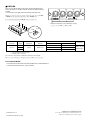
ANALOG OUT
DA CARD
MODEL LMY4-DA
SIGNAL SIGNAL SIGNAL SIGNAL
CH4 CH3 CH2 CH1
The green LED lights up at 34 dB before clipping.
■ LMY4-DA
This is a four-channel analog output card. Set the maximum output
level in the range of +15 dB to +24 dB. The factory default setting is
+24 dB.
You can install up to eight cards in the analog output box AO8.
Output GAIN Actual Source For Use With
Output Level
Connector
Terminals switch Impedance Nominal
Nominal Max. Before Clip
+24 dB +10 dB (2.45 V)* +24 dB (12.3 V)*
XLR-3-32 type
CH 1-4 +18 dB 150 Ω 600 Ω Lines +4 dB (1.23 V)* +18 dB (6.16 V)*
+15 dB +1 dB (870 mV)* +15 dB (4.36 V)*
(Balanced)**
* 0 dB is referenced to 0.775 Vrms.
** 1=GND, 2=HOT, 3=COLD
DA Conversion: 24 bit linear +3 bit floating, 128 times oversampling.
+
2
4
d
B
+
1
5
d
B
+15dB
+18dB
+24dB
1
2
3
4
+
1
8
d
B
YAMAHA CORPORATION
V510070 R1 1 IP 2 Pro Audio & Digital Musical Instrument Division
P.O. Box 3, Hamamatsu, 430-8651, Japan
00 07 800 AP Printed in Japan
-
 1
1
-
 2
2


Yamaha Computer Drive AI8 Instrukcja obsługi
- Typ
- Instrukcja obsługi
w innych językach
- čeština: Yamaha Computer Drive AI8 Uživatelský manuál
- español: Yamaha Computer Drive AI8 Manual de usuario
- italiano: Yamaha Computer Drive AI8 Manuale utente
- Deutsch: Yamaha Computer Drive AI8 Benutzerhandbuch
- svenska: Yamaha Computer Drive AI8 Användarmanual
- português: Yamaha Computer Drive AI8 Manual do usuário
- français: Yamaha Computer Drive AI8 Manuel utilisateur
- 日本語: Yamaha Computer Drive AI8 ユーザーマニュアル
- Türkçe: Yamaha Computer Drive AI8 Kullanım kılavuzu
- English: Yamaha Computer Drive AI8 User manual
- dansk: Yamaha Computer Drive AI8 Brugermanual
- русский: Yamaha Computer Drive AI8 Руководство пользователя
- Nederlands: Yamaha Computer Drive AI8 Handleiding
- română: Yamaha Computer Drive AI8 Manual de utilizare