Yamaha PLG100 Instrukcja obsługi
- Kategoria
- Instrumenty muzyczne
- Typ
- Instrukcja obsługi
Niniejsza instrukcja jest również odpowiednia dla


2
Precautions
● Do not expose the plug-in board to direct sunlight, ex-
cessive humidity, high temperatures, excessive dust or
strong vibrations.
● Before handling the plug-in board, be sure to touch a
metal surface to discharge any static electricity which
may be in your body.
● When holding the plug-in board, do not touch the in-
side area of the circuit board or apply excessive pres-
sure to the board, and be sure to protect the board from
contact with water or other liquids.
● Before installing the plug-in board onto a tone genera-
tor/sound card, unplug the power connector of your com-
puter.
● Before connecting the computer to other devices, turn
off the power switches of all devices.
● Yamaha is not responsible for loss of data through com-
puter malfunctions or operator actions.
● The plug-in board contains no user-serviceable parts,
so never touch the inside area of the circuit board or
tamper with the electronic circuitry in any way. Doing
so may result in electrical shock or damage to the plug-
in board.
YAMAHA CANNOT BE HELD RESPONSIBLE
FOR DAMAGE CAUSED BY IMPROPER
CARE AND USE OF THE PLUG-IN BOARD.
FCC INFORMATION (U.S.A.)
1. IMPORTANT NOTICE: DO NOT MODIFY THIS UNIT!
This product, when installed as indicated in the instructions contained in this manual, meets FCC requirements. Modifications
not expressly approved by Yamaha may void your authority, granted by the FCC, to use the product.
2. IMPORTANT: When connecting this product to accessories and/or another product use only high quality shielded cables.
Cable/s supplied with this product MUST be used. Follow all installation instructions. Failure to follow instructions could void
your FCC authorization to use this product in the USA.
3. NOTE: This product has been tested and found to comply with the requirements listed in FCC Regulations, Part 15 for Class
”B” digital devices. Compliance with these requirements provides a reasonable level of assurance that your use of this product
in a residential environment will not result in harmful interference with other electronic devices. This equipment generates/
uses radio frequencies and, if not installed and used according to the instructions found in the users manual, may cause
interference harmful to the operation of other electronic devices. Compliance with FCC regulations does not guarantee that
interference will not occur in all installations. If this product is found to be the source of interference, which can be determined
by turning the unit ”OFF” and ”ON”, please try to eliminate the problem by using one of the following measures:
Relocate either this product or the device that is being affected by the interference.
Utilize power outlets that are on different branch (circuit breaker or fuse) circuits or install AC line filter/s.
In the case of radio or TV interference, relocate/reorient the antenna. If the antenna lead-in is 300 ohm ribbon lead, change
the lead-in to co-axial type cable.
If these corrective measures do not produce satisfactory results, please contact the local retailer authorized to distribute this
type of product. If you can not locate the appropriate, please contact Yamaha Corporation of America, Electronic Service
Division, 6600 Orangethorpe Ave, Buena Park, CA 90620
* This applies only to products distributed by YAMAHA CORPORATION OF AMERICA.
* The company names and product names in this Owner’s Manual are the trademarks or regis-
tered trademarks of their respective companies.
* The screens as illustrated in this owner’s manual are for instructional purposes only, and may
appear somewhat different from the ones of your instrument.
CANADA
This Class B digital apparatus complies with Canadian ICES-003.
Cet appareil numérique de la classe B est conforme à la norme NMB-003 du Canada.
• This applies only to products distributed by Yamaha Canada Music Ltd.
• Ceci ne s’applique qu’aux produits distribués par Yamaha Canada Musique Ltée.

3
Introduction
Thank you for purchasing the Yamaha XG Plug-in board PLG100-DX.
The PLG100-DX is a plug-in board that offers a six-operator FM generator equivalent to the one that
made the DX7 series so famous. The PLG100-DX is compatible with the XG plug-in system, and you
can install it into the MU128 or any other tone generator or sequencer that supports XG plug-ins. Once
it’s installed, the unique FM tone generator voices that built the reputation of the DX series will be right
at your fingertips, ready to play. The PLG100-DX has 912 preset DX series voices built right in, and
you can send the DX7 and DX7II voice data through MIDI.
To install your PLG100-DX correctly, and to ensure full enjoyment of its outstanding functions, be sure
to read this manual very carefully. After you finish reading your owner’s manual, be sure to keep it
someplace safe, where you can refer to it whenever you have a question about your PLG100-DX.
About the XG Plug-in System
With the Yamaha XG Plug-in System, you can expand your tone generation system by simply
mounting an optional board onto the “mother” tone generator/sound card. For example, you will
be able to use extra voices from a different sound synthesis such as Virtual Acoustic Synthesis,
apply a completely new dimension to your music, and/or add the latest technology to your music.
About DX-XG
The DX Extension for XG (“DX Extension for XG” is abbreviated to DX-XG) included in the
PLG100-DX significantly enhances and expands the musical capabilities of the XG format with
the superior sound and expressive potential of Yamaha FM synthesis. The PLG100-DX supports
the same powerful FM synthesis voices as Yamaha’s legendary DX7. Plug this board into your
tone generator/sound card for 912 unbelievable FM voices with up to 16-note polyphony.
About the PLG100-DX ......................................... 4
Features of the PLG100-DX ..................................... 4
Installing the PLG100-DX ......................................... 4
Included Items .......................................................... 5
Necessary Items that Are Not Included .................. 5
Specifications ........................................................... 6
About the CD-ROM ................................................... 7
Installing and Starting the Plug-in Software .......... 8
FM Tone Generation ........................................... 10
Operators ................................................................ 10
Combinations of Two Operators ........................... 11
Carrier and Modulator ............................................ 12
Harmonics ............................................................... 13
Algorithms............................................................... 14
Feedback ................................................................. 14
Essentials for Determining Voices ....................... 15
Memory Buffer Configuration........................ 18
DX Voice Selection................................................ 19
Choosing the Voices to be Used........................... 19
Specifying Part/Performance Layers .................... 20
Editing DX Part Parameters............................ 21
PLG100-DX Part Parameters ................................. 22
PLG100-DX System Parameters.................... 26
System Parameters ................................................ 27
Appendix ................................................................... 28
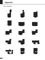
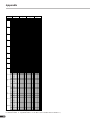
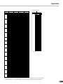
Chart of Algorithms ................................................ 28
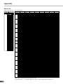
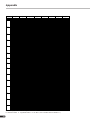
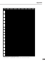
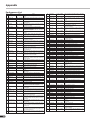
Voice List................................................................. 30
Performance List .................................................... 38
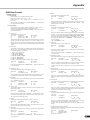
MIDI Data Format .................................................... 39
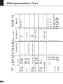
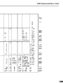
MIDI Implementation Chart .................................... 50
Glossary .................................................................. 52
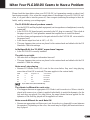
When Your PLG100-DX Seems to Have a Problem..
59
Conditions for Using the Software........................ 61
Guide to User Support Services ........................... 62
Table of Contents

4
About the PLG100-DX
Features of the PLG100-DX
• Features the same FM tone generator that has won acclaim in the DX
series synthesizers.
The PLG100-DX employs an FM tone generator system, with six operators and 32
algorithms, that has been a favorite of musicians in DX series synthesizers like the
DX7 and the DX7II.
• Maximum 16 voice simultaneous polyphony
Ensures maximum 16 voice simultaneous polyphony equal to the DX7 and DX7II.
Furthermore, by installing multiple PLG100-DX boards, the maximum polyphony can
be increased to 128 voices (when eight boards are installed). By installing, for ex-
ample, three PLG100-DX boards in the MU128 tone generator, maximum polyphony
will be 48 voices.
• 912 preset voices
The PLG100-DX already has 912 preset voices built right in. From electric piano to
bass, and reaching all the way to effect sounds, the preset voices have been selected for
usability centering on the sounds that made the DX series famous.
• Voice data can be exchanged in bulk between the DX7 and the DX7II
Because the PLG100-DX is compatible with the DX series, it can be used for bulk
transfer of voice parameters between the DX7 and the DX7II. The DX7 and DX7II can
be used as editors for the PLG100-DX. By using the edit software for the DX7 and the
DX7II, editing can be done for the PLG100-DX. Voice parameters for the DX1, DX7S,
TF1 (such as the TX816) TX7 and the TX802 are also supported.
• Some voices may sound slightly different than the voices of the devices mentioned above.
• Comes equipped with a low pass filter, a high pass filter and a two-band
equalizer.
A low pass filter, a high pass filter and a two-band equalizer have been installed in the
PLG100-DX. These features can be used together with the voice editing parameters for
the FM tone generator to create new voices. Even if you install the PLG100-DX in a
platform that doesn’t have these functions, the filters and EQ built into the PLG100-
DX will work.
• Compatible with the XG Plug-In system
Because the PLG100-DX is an XG plug-in board, it can be installed in any XG plug-in
tone generator, like the MU128.
Installing the PLG100-DX
To install your PLG100-DX board, see the manual that came with the “mother” tone gen-
erator (such as the MU128 or SW1000XG) or synthesizer.

5
Included Items
The items below are packaged together with your new PLG100-DX. Before using your
board, be sure to check that everything has been included. In the rare event that some item
is missing, please contact the store where you bought your PLG100-DX as soon as pos-
sible.
● PLG100-DX Board
● PLG100-DX Owner’s Manual
● CD-ROM “XGtools”
Necessary Items that Are Not Included
XG tone generator or synthesizer
To use your PLG100-DX, you will need an XG tone generator or synthesizer equipped
with an XG Plug-in platform function that is compatible with the XG Plug-in system,
such as the MU128 or SW1000XG.
The MU128 and SW1000XG are equipped with each of the XG Plug-in platform func-
tions, and can be used for installing the PLG100-DX.
The software programs explained below will put the functions of the PLG100-DX right
at your fingertips, helping you get the most enjoyment out of it.
XGworks(lite)
When you use Yamaha’s XGworks(lite) as your sequence software, you can take ad-
vantage of the two editing software programs explained below, the “DX Simulator”
and the “DX Easy Editor.” These programs make it really easy to edit the voices of
your PLG100-DX board.
DX Easy Editor
The DX Easy Editor lets you indirectly change the PLG100-DX voices by changing the
part parameters. It’s not for directly editing the voice parameters. Using this software,
you can edit both the XG part parameters (XG parameters) that are shared by all the
parts, and the native part parameters that are specially for the PLG100-DX (DX param-
eters). The changed parameters can be either inserted into the song as events, or saved
as a DX parameter file.
Because the DX Easy Editor is plug-in software for XGworks(lite), you must have
XGworks(lite) in order to use it.
The DX Easy Editor is included on the CD-ROM that was packaged with your PLG100-
DX board.
About the PLG100-DX

6
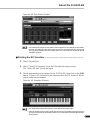
DX Simulator
The DX Simulator is special software for editing the custom voices of the PLG100-
DX. When you start up the program, an image of the DX7 front panel is displayed on
your computer screen. Using your mouse to operate the buttons and sliders, you can
edit voices just like using a real DX7. You can also display an edit list where you can
edit voices while checking all the parameters in a table on the screen. The edited voice
data can be either saved in memory or to a file, or can be inserted into a track as bulk
data.
Because the DX Simulator is plug-in software for XGworks(lite), you must have
XGworks(lite) in order to use it.
The DX Simulator is included on the CD-ROM that was packaged with your PLG100-
DX board.
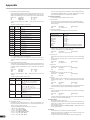
Tone Generator Type:
FM tone generator with six operators and 32 algorithms
Maximum Simultaneous Polyphony:
16 notes (latest note priority)
By using multiple boards in combination, polyphony can be expanded to a maximum of 128 notes (with 8
boards)
Filters:
Part EQ (two band), low pass filter, high pass filter (effective only when the platform for the PLG100-DX
has no filter functions)
Interface:
XG Plug-in connector
Number of Voices:
912 preset voices, 64 custom voices
Bulk Information that Can Be Received from Other Devices:
DX7 Voice Edit Buffer, Packed 32 Voice
DX7II Voice Edit Buffer, Packed 32 voice, a portion of the Additional Edit Buffer, a portion of the
Packed 32 Additional (Pitch EG range, rs, velocity switch, Unison detune, AMS, Random pitch,
Poly/Mono, Unison Sw, Pitch bend range, step, Portamento mode, step, time)
Parameter Changes that Can Be Received from Other Devices:
DX7 VCED, a portion of ACED (Pitch EG range, rs, velocity switch, Unison detune, AMS, Random
pitch, Poly/Mono, Unison Sw, Pitch bend range, step, Portamento mode, step, time)
Dimensions:
138.5mm (W) x 89.0mm (D) x 8.5mm (H)
Weight 63g
Included Items:
Owner’s Manual, CD-ROM x 1
*Specifications or dimensions may change without notice due to improvements in this product.
Specifications
About the PLG100-DX

7
About the CD-ROM
In addition to the two plug-in software programs, DX Simulator and DX Easy Editor, the
CD-ROM that was packaged with your board also contains several demonstration songs
that showcase the special features of the PLG100-DX, and also performance data (voice
settings) for use in the platform where you have installed your PLG100-DX. The demon-
stration songs can be enjoyed by playing them with sequence software like XGworks
V2.0 or XGworks(lite), or with a QY700. (A platform for connecting the PLG100-DX is
also necessary.) Use the same sequence software or device to send the performance data
as bulk data to the platform for the PLG100-DX.
● Demonstration Songs
“Ie Kia Bara Hein” (IeKiaBar.MID) by Noritaka Ubukata (Shofuku)
The title of the song means “What kind of spell is this?” in the Hindi language. It
features the voice that simulates a santur (hammer dulcimer) together with a sitar.
“DX VOICE” (DXVoice.MID) by Noritaka Ubukata (Shofuku)
Starting with the electric piano, this song features a series of the sounds of DX7
Shofuku. Unlike sampling, this music offers the listener subtle variation in the sound
caused by changes in velocity. Another special feature is the FM choir, where a more
realistic sound is created by combining FM synthesis with sampled human voices.
“Vel&EffectWorks1” (V1_EfWk1.MID)
“Vel&EffectWorks2” (V1_EfWk2.MID)
“DX Short Demo” (DxShtDM.MID) by Yasuhiko Fukuda (Shofuku)
These songs showcase a unique feature of FM: the violent changes in sound that are
caused by velocity.
“80’s Pops” (80Pop.MID) by Katsumi Nagae (Idecs Inc.)
Recalls the pop scene of the 80’s with synpads and metallic sounds like dum bells.
“D-Rock” (D-Rock.MID) by Katsumi Nagae (Idecs Inc.)
This song brings back the digital rock sound using the noise and SE system voices
that only DX has.
If you want to use digital noise, there is nothing that works like DX!
“EP Ballade” (EP.MID) by Katsumi Nagae (Idecs Inc.)
If it’s ballads you want—well, there is nothing like DX electric piano.
The voice in the electric piano part will also work with different electric pianos. Try
playing the song with different piano voices.
About the PLG100-DX

8
“House” (HOUSE.MID) by Katsumi Nagae (Idecs Inc.)
The typical house music sound is simulated in this song, which experiments with
reproducing sampling phrases using the DX Voice system. In addition, the second
half of the song features the metalic sound that is a strong point of the DX.
“Jungle” (DXJungle.MID) by Katsumi Nagae (Idecs Inc.)
This song adds a touch of Chinese feeling to the Jungle. The Oriental image is under-
scored by the “CHINA_S&” and “IMAGE9” plug-in SE voices.
If no sounds are played, or if you experience other problems with playback, see Ap-
pendix “When Your PLG100-DX Seems to Have a Problem” (→P. 59).
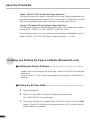
■ Installing the Plug-in Software.......................................................
Double-click on the Setup.exe file in the Plug_ folder on the CD-ROM to start the
installation.
Click on “Next” or “Yes” as these words appear on the screen to complete the in-
stallation.
Installing and Starting the Plug-in Software (Windows95 only)
■ Starting the DX Easy Editor............................................................
1. Start XGworks(lite).
2. Select “DX Easy Editor” from the XGworks(lite) plug-in menu.
The “Select DX Part” dialog will open.
3. Set the part numbers to be assigned to the PLG100-DX, then click on the [OK]
button. If there is DX bulk data in the sequence data, the DX mark will be dis-
played under the part number.
About the PLG100-DX

9
Open the DX Easy Editor Window
• For details about using the DX Easy Editor, see the help file that comes with the DX Easy Editor.
• If the DX Easy Editor does not appear on the Plug-In menu of XGworks(lite), the program may
not be properly installed in the XGworks(lite) folder. You can install it by running the plug-in
installation program.
■ Starting the DX Simulator...............................................................
1. Start XGworks(lite).
2. Select “Select DX Simulator” from the XGworks(lite) plug-in menu.
The “Select DX Part” dialog will open.
3. Set the part numbers to be assigned to the PLG100-DX, then click on the [OK]
button. If there is DX bulk data in the sequence data, the DX mark will be dis-
played under the part number.
Open the DX Simulator Window
About the PLG100-DX
• For details about using the DX Simulator, see the help file that comes with it.
• If the DX Simulator does not appear on the Plug-In menu of XGworks(lite), the program may not
be properly installed in the XGworks(lite) folder. You can install it by running the plug-in instal-
lation program.

10
FM Tone Generation
Before actually editing the PLG100-DX voices, let’s get an idea of how the FM tone generator is
put together.
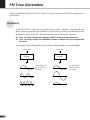
Operators
In the PLG100-DX, there are six special devices called “operators” that generate sine
waves. These six operators are combined in various ways to make up the different voices
produced by the PLG100-DX. The operators have the following two functions:
(1) They can freely change the frequency (pitch) of the generated sine wave.
(2) They can freely change the amplitude (volume or output level) of the generated
sine wave.
A sine wave is the fundamental wave of a note, with absolutely no overtones added.
Command
Operator
The frequency of
the sine wave is
changed.
Command
Operator
The amplitude
of the sine wave
is changed.

11
FM Tone Generation
Although the six operators can be combined in myriad ways, here the fundamental combi-
nations that involve two operators will be explained.
Two operators can be combined in the following two ways (the two operators will be
called A and B respectively):
(1) Horizontal Combination
When the two operators are combined horizontally, the sound generated by each is mixed
with the sound from the other. The actual sound (sine wave) is produced by A and B acting
together.
Combinations of Two Operators
(2) Vertical Combination
When the two operators are combined vertically, the upper operator B works to change the
sound of the lower operator A, and a complex waveform with many overtones added to it
will be the output from operator A. In this situation, the B operator serves only to change
the sound of operator A, and does not generate the actual sound. Operator A generates the
actual sound as it undergoes changes caused by B. When the upper operator works to
change the sound of the lower operator in this way, it is called FM modulation (or simply
modulation).
When these are put together, it looks like this:
• Horizontal Combination The two operators both generate the sound.
• Vertical Combination One operator is for changing the sound of the other operator.
One operator is for making the sound.
When two operators are combined vertically in this way, they both work completely dif-
ferently.
A B
The actual sound is generated by
A and B together
B changes the sound of A (it generates no tone).
While A undergoes changes caused by B, it generates
the actual sound.
B
A
Mixed sound of A and B

12
(3)
FM Tone Generation
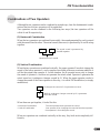
To distinguish the two operators when they are combined vertically, they are called the
“Carrier” and the “Modulator.”
• Carrier ................. The operator in the lowest position, that produces the actual sound. (Called A
in the previous section.)
• Modulator............ An operator positioned above another operator, which changes (modulates)
the sound of the next operator down. (Called B in the previous section.)
When there are three or more operators, each operator is classified as a carrier or modula-
tor in the same way.
Carrier and Modulator
(1) When all the operators are combined horizontally, there is no modulator and they are
all carriers. Because there is no modulation, all waveforms generated by the carriers
are sine waves.
(2) When three operators are piled vertically, only the lowest operator is a carrier. The
modulator on the top modulates the lower modulator, and the modulated waveform
from the lower modulator in turn modulates the carrier. The modulation of the carrier
becomes deeper and the sound output has more overtones.
(3) Here there are two carriers and one modulator. The modulator modulates the carrier
immediately below it. The modulated carrier generates sound with overtones. The
other carrier produces a pure sine wave. Finally, the sound from the two carriers is
mixed to form the whole sound.
(4) Here there is one carrier and two modulators. The two modulators each independently
modulate the single carrier. Since the carrier is modulated by the two modulators, it
generates a sound that has more overtones.
(5) Here there are two sets of two operators that have been combined vertically. In each of
them, the modulator modulates the carrier immediately below it, and the carrier gen-
erates a sound that has overtones. Finally, the sound from the two carriers is mixed to
form the whole sound.
“C” Carrier
“M” Modulator
C C C
M
M
C
M
C
C
M M
C
M M
C C
(1)
(2)
(4)
(5)

13
FM Tone Generation
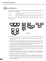
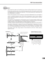
Harmonics
Most sounds are made up of multiple tones that are different than the pitch (frequency).
Within these multiple tones, the one that determines the pitch of the entire sound is called
the fundamental tone (fundamental frequency). All the tones besides the fundamental tone
are called partials or overtones.
When all the harmonics that are related to a particular fundamental tone are arranged in
order, it is called a harmonic series. Each tone in the harmonic series is given a name in
order, with the fundamental tone being one, followed by the second harmonic, third har-
monic and so on.
The frequency of each harmonic in the harmonic series is a natural number multiple of the
frequency of the fundamental tone. Overtones that have frequencies that are not natural
number multiples of the fundamental are called unharmonic overtones.
Generally, the more harmonics the tone has, the brighter the sound. On the other hand, if
the amount of harmonics is reduced, the tone will sound darker. Furthermore, the voice
will change a lot according to the type and volume of the harmonics. For example, if there
are a lot of high pitched harmonics in the tone, it will have a brilliant, crisp sound. On the
other hand, a tone with a large amount of lower harmonics will have a rather massive,
dignified sound.
Harmonics
Waveform
Level
Time
Graph of the Harmonics
that Make Up the Tone
Level
Harmonics
Harmonics
Fundamental Wave
Second Harmonic
Third Harmonic
Natural Harmonic Series
(when C1 is the fundamental tone)
Frequency
Eighth Harmonic
Seventh Harmonic
Sixth Harmonic
Fifth Harmonic
Fourth Harmonic
Third Harmonic
Second Harmonic
Fundamental
Fourth Harmonic
Third Harmonic
Second Harmonic
Fundamental

14
FM Tone Generation
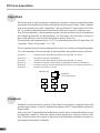
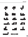
While there may be only two ways to combine two operators, when you start talking about
six operators, the number of possible combinations becomes much larger. These combina-
tions of six operators are called “algorithms,” and in both the DX7 series and the PLG100-
DX, 32 of these combinations have been selected that can be used for creating voices.
In an FM tone generator, which operators work as carriers and which work as modulators
are changed dynamically by the algorithms. For this reason, the first thing you have to
know when editing a voice is which algorithm is used by that voice.
The algorithms are numbered from 1 to 32. For information about the 32 algorithms, see
“Appendix, Chart of Algorithms” (→P. 28).
The six operators have also been numbered from one to six to help in distinguishing them.
Let’s take algorithm 28 as an example. In this algorithm, the operators work as follows:
Algorithms
Operator 1 ............. Outputs sounds while being modulated by Operator 2 (Carrier).
Operator 2 ............. Modulates Operator 1 (Modulator).
Operator 3 ............. Outputs sounds while being modulated by Operator 4 (Carrier)
Operator 4 ............. Modulates Operator 3 while being modulated by Operator 5 (Modulator)
Operator 5 .............
Modulates Operator 4 while being modulated with its own feedback (Modulator).
Operator 6 ............. Outputs a sine wave (Carrier)
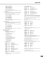
Feedback
Feedback is a function where a portion of the output of an operator is returned back to the
operator again, where it is used to modulate the operator itself. Using feedback results in a
deeper sound.
Every one of the 32 algorithms has feedback set in one location. Among them there is even
one algorithm, number 4, where the output of three operators as a group is used as feed-
back. When a portion of the output of operator 4 in this algorithm is returned to operator 6,
an extremely deep sound is obtained.
Feedback
(See next section)
2 4
1 3 6
5
Algorithm 28

15
FM Tone Generation
Essentials for Determining Voices
Voices are determined by the following main elements:
(1) The output level from each operator (OUTPUT LEVEL).
(2) The frequency of the tone put out by each operator
(OUTPUT FREQUENCY).
(3) The feedback level (FEEDBACK LEVEL).
(4) The Envelope Generator (EG).
Each of these will be explained in order.
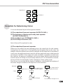
(1) The output level from each operator
When voices are edited, the most important point is the output level for each operator.
Among these, the output level of the modulator has the largest effect on the voice. For
example, when two operators are vertically combined, and the output level of modulator B
is set to zero, the output waveform of carrier A will be a simple sine wave (a dark tone with
no harmonics included). If the output level of the modulator is gradually increased from
this condition, the amount of modulation will become deeper and the output waveform
from the carrier will change to one with many harmonics in it. As the harmonics increase,
the tone will also become brighter, finally changing to a harsh, grating sound.
From this we can conclude that the degree of modulation, which equals the brightness of
the sound, changes in relation to the output level of the modulator.
Feedback
5
4
6
2
1
3
Algorithm 4
The waveform changes a lot.
A
B
A
B
A
B
Modulator
Output Level = 0
Carrier
Sine wave
The output level is
increased slightly.
The waveform changes
slightly.
The output level is
greatly increased.

16
FM Tone Generation
On the other hand, because the carrier actually makes the sound, changing the output level
causes a change in the strength (volume) of the sound. If there is only one carrier, this will
simply cause the overall volume to change. However, if there are multiple carriers in the
algorithm, the timbre may also be changed as the balance in volume between the different
carriers is changed.
To summarize these points:
• The voice changes according to the output level of the modulators.
• The volume changes according to the output level of the carriers. The voice may also be changed
as the balance in volume between multiple carriers changes.
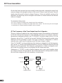
(2) The Frequency of the Tone Output from Each Operator
The type of harmonics added to the carrier output by means of the modulator is determined
by the ratio between the frequencies of the modulator and carrier. For example, when two
operators are combined vertically, and “F COARSE” for both of them is set to 1.00, the
frequency ratio will be 1:1 and the first, second, third and following whole number series
harmonics will be generated in order. This type of harmonic configuration is called a
sawtooth wave, and is used for making voices like brass, strings, or piano.
If the “F COARSE” for the modulation in this situation is changed to 2.00, the frequency
ratio will be 1:2, and the odd numbered harmonics, the first, third and fifth and following
harmonics will be generated. This harmonic configuration is called a rectangular wave,
and is used for creating voices for woodwinds like the clarinet and oboe.
Furthermore, if “F FINE” is used so that the frequency ratio is not a whole number, many
non-integer overtones will be produced. The sound can be used for creating metallic sounds,
the noise when strings are hit with something, or breath noise.
A
B
A
B
Modulator
Frequency
ratio 1:1
Carrier
Sawtooth wave
Frequency
ratio 1:2
Rectangular wave

17
FM Tone Generation
(3) FEEDBACK LEVEL
By raising the feedback level, the modulation deepens, and the timbre of the sound be-
comes brighter.
(4) Envelope Generator (EG)
The EG creates the changes over time in the output level from the instant a key on the
keyboard is pressed to the time that the sound disappears.
If you listen to various musical instruments, you soon realize that besides the differences
in the timbre of the sounds they create, there is a large difference in the way that the sound
first comes out, and in the way in which it fades away. For example, the sound from a
piano gets very loud the instant a key is struck, then the volume gradually fades away, even
if you continue pressing down the key. Also, if you look at the change in tone over time,
there is a bright sound with a lot of overtones the moment the key is struck, but the over-
tones soon fade away, and the tone takes on a darker aspect.
The function that produces the instrument’s change in volume and timbre over time is the
EG.
In an FM tone generator, an EG is built into each operator. The EG for the carrier changes
its volume over time, while the EG for the modulator changes the timbre of the sound over
time.

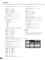
18
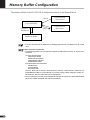
The memory buffer of the PLG100-DX is configured as shown in the diagram below.
Memory Buffer Configuration
• The only voices that can be edited using an editing program like the DX Simulator are the custom
voices.
When using the custom bank
• The following parameters are not valid when using the custom bank because they are saved as voice
parameters.
XG Native Part Parameters
MONO/POLY MODE
BEND PITCH CONTROL
PORTAMENTO SWITCH
PORTAMENTO TIME
PLG100-DX Native Part Parameters
PitchBend Step
Portamento Step
Portamento Mode
However, MONO/POLY MODE, BEND PITCH CONTROL, PORTAMENTO SWITCH, and
PORTAMENTO TIME are received through CC (Control Change). (When changing to another cus-
tom bank voice, that voice will be set to the saved parameters.)
• If an XG System On is received, or part assignment is changed, the custom voices will be initialized, but
the 64 voice VMEM and AMEM areas will not be initialized.
Voice Edit Buffer
Compare
Edit Recall
Edit Recall Buffer
Recall
Preset Memory
(912 Voices)
Custom Voices
(64 Voices)
Store

19
DX Voice Selection
The PLG100-DX voices can be selected just like the voices for the XG tone generator itself.
However, to use the PLG100-DX voices, XG mode or performance mode (PERFORM) must be
selected in the Sound Module Mode of the XG tone generator. Also the part/performance layer
assigned to the PLG100-DX must be specified in the sub-mode (PLUGIN) of the utility mode of
the XG tone generator.
• The displays used below for explaining tone generator operations are from the MU100. The screens may be
different for the tone generator you are using.
• For tone generators, like the SW1000XG, that have no display, the settings must be sent as System Exclusive
Messages (
→
MIDI Data Format).
• The SW1000XG does not support the Performance Mode.
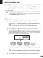
■ Selecting the Voices to be Used .............................................................................
1. Set the Sound Module Mode of the XG tone generator to XG or PERFORM.
When XG is selected, the tone generator will enter Multi Mode.
When PERFORM is selected, the tone generator will enter Performance Play Mode.
• DX voices can be selected only when the Part Mode is set to Normal.
• In XG Mode, DX voices can be used as one part, and in Performance Mode, as one layer.
2. Press the [SELECT / ] buttons, and move the cursor to the bank number.
3. Press the [VALUE / ] buttons and select the bank of the voice you wish to use.
Depending on the bank you have selected, one of the following will appear in the bank
number location of the display: 000,064 to 082, 096 to 109 (DX-XG/A); 000,064 to
082 (DX-XG/B); 000 (DX-XG/SFX) or 000 (Custom).
When a DX voice is selected, a DX voice icon will appear in the icon area of the
display.
• Please note that the bank number displayed may be one for the XG tone generator itself. You can make
sure that it is one for the PLG100-DX by checking for a DX voice icon in the icon area of the display.
4. Press the [SELECT / ] buttons, and move the cursor to the program number.
Bank number display location
Icon display area
DX-XG/A DX-XG/B
Custom
DX-XG/SFX

20
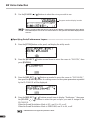
5. Use the [VALUE / ] buttons to select the voice you wish to use.
DX Voice Selection
• When a program number that does not exist for the PLG100-DX is selected when the chosen bank is
from 000 to 099, the icon for the voice selected in the XG tone generator itself will be displayed in the
icon area.
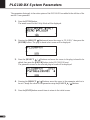
■ Specifying Parts/Performance Layers....................................................................
1. Press the [UTIL] button on the panel, and display the utility mode.
2. Press the [SELECT ] button several times to move the cursor to “PLUGIN”, then
press [ENTER].
3. Press the [SELECT / ] buttons as needed to move the cursor to “PLG100-DX,”
then press the [ENTER] button. An editing screen for the system parameters expanded
by the PLG100-DX will be displayed.
4. Press the [SELECT / ] buttons several times to display “PartAssign,” then press
the [VALUE
/ ] buttons to select the part or layer you want to assign to the
PLG100-DX.
When the Sound Modulation Mode is XG, use 01 to 16, or off.
When the Sound Modulation Mode is PERFORM, use 01 to 04, or off.
• SW1000XG does not support the performance mode.
Program number display location
Strona się ładuje...
Strona się ładuje...
Strona się ładuje...
Strona się ładuje...
Strona się ładuje...
Strona się ładuje...
Strona się ładuje...
Strona się ładuje...
Strona się ładuje...
Strona się ładuje...
Strona się ładuje...
Strona się ładuje...
Strona się ładuje...
Strona się ładuje...
Strona się ładuje...
Strona się ładuje...
Strona się ładuje...
Strona się ładuje...
Strona się ładuje...
Strona się ładuje...
Strona się ładuje...
Strona się ładuje...
Strona się ładuje...
Strona się ładuje...
Strona się ładuje...
Strona się ładuje...
Strona się ładuje...
Strona się ładuje...
Strona się ładuje...
Strona się ładuje...
Strona się ładuje...
Strona się ładuje...
-
 1
1
-
 2
2
-
 3
3
-
 4
4
-
 5
5
-
 6
6
-
 7
7
-
 8
8
-
 9
9
-
 10
10
-
 11
11
-
 12
12
-
 13
13
-
 14
14
-
 15
15
-
 16
16
-
 17
17
-
 18
18
-
 19
19
-
 20
20
-
 21
21
-
 22
22
-
 23
23
-
 24
24
-
 25
25
-
 26
26
-
 27
27
-
 28
28
-
 29
29
-
 30
30
-
 31
31
-
 32
32
-
 33
33
-
 34
34
-
 35
35
-
 36
36
-
 37
37
-
 38
38
-
 39
39
-
 40
40
-
 41
41
-
 42
42
-
 43
43
-
 44
44
-
 45
45
-
 46
46
-
 47
47
-
 48
48
-
 49
49
-
 50
50
-
 51
51
-
 52
52


Yamaha PLG100 Instrukcja obsługi
- Kategoria
- Instrumenty muzyczne
- Typ
- Instrukcja obsługi
- Niniejsza instrukcja jest również odpowiednia dla
w innych językach
- čeština: Yamaha PLG100 Uživatelský manuál
- español: Yamaha PLG100 Manual de usuario
- italiano: Yamaha PLG100 Manuale utente
- Deutsch: Yamaha PLG100 Benutzerhandbuch
- svenska: Yamaha PLG100 Användarmanual
- português: Yamaha PLG100 Manual do usuário
- français: Yamaha PLG100 Manuel utilisateur
- Türkçe: Yamaha PLG100 Kullanım kılavuzu
- English: Yamaha PLG100 User manual
- dansk: Yamaha PLG100 Brugermanual
- русский: Yamaha PLG100 Руководство пользователя
- suomi: Yamaha PLG100 Ohjekirja
- Nederlands: Yamaha PLG100 Handleiding
- română: Yamaha PLG100 Manual de utilizare
Powiązane artykuły
-
Yamaha PLG150 Instrukcja obsługi
-
Yamaha DX100 instrukcja
-
Yamaha TX-81Z Instrukcja obsługi
-
-
-
-
-
-
-