Yamaha MG24 Instrukcja obsługi
- Kategoria
- Sprzęt muzyczny
- Typ
- Instrukcja obsługi

MIXING CONSOLE
Owner’s Manual
MG32/14 FX
MG24/14 FX
E

MG32/14FX, MG24/14FX
2
The above warning is located on the rear
of the unit
• Explanation of Graphical Symbols
The lightning flash with arrowhead symbol
within an equilateral triangle is intended to
alert the user to the presence of uninsulated
“dangerous voltage” within the product’s
enclosure that may be of sufficient magnitude
to constitute a risk of electric shock to persons.
The exclamation point within an equilateral
triangle is intended to alert the user to the pres-
ence of important operating and maintenance
(servicing) instructions in the literature
accompanying the product.
IMPORTANT SAFETY INSTRUCTIONS
CAUTION: TO REDUCE THE RISK OF
ELECTRIC SHOCK, DO NOT REMOVE
COVER (OR BACK). NO USER-SERVICEABLE
PARTS INSIDE. REFER SERVICING TO
QUALIFIED SERVICE PERSONNEL.
CAUTION
RISK OF ELECTRIC SHOCK
DO NOT OPEN
1 Read these instructions.
2 Keep these instructions.
3 Heed all warnings.
4 Follow all instructions.
5 Do not use this apparatus near water.
6 Clean only with dry cloth.
7 Do not block any ventilation openings. Install in
accordance with the manufacturer’s instruc-
tions.
8 Do not install near any heat sources such as
radiators, heat registers, stoves, or other appa-
ratus (including amplifiers) that produce heat.
9 Do not defeat the safety purpose of the polar-
ized or grounding-type plug. A polarized plug
has two blades with one wider than the other. A
grounding type plug has two blades and a third
grounding prong. The wide blade or the third
prong are provided for your safety. If the pro-
vided plug does not fit into your outlet, consult
an electrician for replacement of the obsolete
outlet.
10 Protect the power cord from being walked on or
pinched particularly at plugs, convenience
receptacles, and the point where they exit from
the apparatus.
11 Only use attachments/accessories specified by
the manufacturer.
12 Use only with the cart, stand,
tripod, bracket, or table spec-
ified by the manufacturer, or
sold with the apparatus.
When a cart is used, use cau-
tion when moving the cart/
apparatus combination to
avoid injury from tip-over.
13 Unplug this apparatus during lightning storms
or when unused for long periods of time.
14 Refer all servicing to qualified service person-
nel. Servicing is required when the apparatus
has been damaged in any way, such as power-
supply cord or plug is damaged, liquid has been
spilled or objects have fallen into the apparatus,
the apparatus has been exposed to rain or mois-
ture, does not operate normally, or has been
dropped.
WARNING
TO REDUCE THE RISK OF FIRE OR ELECTRIC SHOCK,
DO NOT EXPOSE THIS APPARATUS TO RAIN OR MOISTURE.

MG32/14FX, MG24/14FX
3
PRECAUTIONS
PLEASE READ CAREFULLY BEFORE PROCEEDING
* Please keep this manual in a safe place for future reference.
WARNING
Always follow the basic precautions listed below to avoid the possibility of serious injury or even death from electrical shock,
short-circuiting, damages, fire or other hazards. These precautions include, but are not limited to, the following:
• Only use the voltage specified as correct for the device. The
required voltage is printed on the name plate of the device.
• Use only the included power cord.
• Do not place the power cord near heat sources such as
heaters or radiators, and do not excessively bend or otherwise
damage the cord, place heavy objects on it, or place it in a
position where anyone could walk on, trip over, or roll anything
over it.
• Be sure to connect to an appropriate outlet with a protective
grounding connection. Improper grounding can result in
electrical shock.
• Do not open the device or attempt to disassemble the internal
parts or modify them in any way. The device contains no
user-serviceable parts. If it should appear to be
malfunctioning, discontinue use immediately and have it
inspected by qualified Yamaha service personnel.
• Do not expose the device to rain, use it near water or in damp
or wet conditions, or place containers on it containing liquids
which might spill into any openings.
•Never insert or remove an electric plug with wet hands.
• If the power cord or plug becomes frayed or damaged, or if
there is a sudden loss of sound during use of the device, or if
any unusual smells or smoke should appear to be caused by it,
immediately turn off the power switch, disconnect the electric
plug from the outlet, and have the idevice inspected by
qualified Yamaha service personnel.
• If this device should be dropped or damaged, immediately turn
off the power switch, disconnect the electric plug from the
outlet, and have the device inspected by qualified Yamaha
service personnel.
CAUTION
Always follow the basic precautions listed below to avoid the possibility of physical injury to you or others, or damage to the
device or other property. These precautions include, but are not limited to, the following:
• Remove the electric plug from the outlet when the device is not
to be used for extended periods of time, or during electrical
storms.
• When removing the electric plug from the device or an outlet,
always hold the plug itself and not the cord. Pulling by the cord
can damage it.
• When transporting or moving the device, always use two or
more people.
• Before moving the device, remove all connected cables.
• When setting up the product, make sure that the AC outlet you
are using is easily accessible. If some trouble or malfunction
occurs, immediately turn off the power switch and disconnect
the plug from the outlet. Even when the power switch is turned
off, electricity is still flowing to the product at the minimum
level. When you are not using the product for a long time,
make sure to unplug the power cord from the wall AC outlet.
•Avoid setting all equalizer controls and faders to their
maximum. Depending on the condition of the connected
devices, doing so may cause feedback and may damage the
speakers.
• Do not expose the device to excessive dust or vibrations, or
extreme cold or heat (such as in direct sunlight, near a heater,
or in a car during the day) to prevent the possibility of panel
disfiguration or damage to the internal components.
• Do not place the device in an unstable position where it might
accidentally fall over.
•Never block the vent holes during use. Vent holes are located
on the top, bottom, front, rear, and sides of this machine. All
vent holes must remain unblocked to prevent overheating.
To further ensure adequate ventilation, never use this device…
- Upside down or on its side
- In a poorly ventilated location (in a closet, inside a
bookcase, etc.)
- With its rubber footpads removed
- On a thick carpet or other such surface
- While it is inside an unventilated touring case
Failure to observe the above precautions may cause the
device to overheat, resulting in equipment damage and fire
hazard.
• Do not use the device in the vicinity of a TV, radio, stereo
equipment, mobile phone, or other electric devices. Otherwise,
the device, TV, or radio may generate noise.
• Before connecting the device to other devices, turn off the
power for all devices. Before turning the power on or off for all
devices, set all volume levels to minimum.
• Do not insert your finger or hand in any gaps or openings on
the device (vents, etc.).
•Avoid inserting or dropping foreign objects (paper, plastic,
metal, etc.) into any gaps or openings on the device (vents,
etc.). If this happens, turn off the power immediately and
unplug the power cord from the AC outlet. Then have the
device inspected by qualified Yamaha service personnel.
• Do not use the device or headphones for a long period of time
at a high or uncomfortable volume level, since this can cause
permanent hearing loss. If you experience any hearing loss or
ringing in the ears, consult a physician.
• Do not rest your weight on the device or place heavy objects
on it, and avoid use excessive force on the buttons, switches or
connectors.
Power supply/Power cord
Do not open
Water warning
If you notice any abnormality
Power supply/Power cord
Location
Connections
Handling caution

MG32/14FX, MG24/14FX
4
Always turn the power off when the device is not in use.
The performance of components with moving contacts, such as switches, volume controls, and connectors, deteriorates over time. Consult quali-
fied Yamaha service personnel about replacing defective components.
Copying of commercially available music data and/or digital audio files, except for personal use, is strictly prohibited.
Illustrations in this manual are for explanatory purposes only, and may not match the actual appearance of the product during operation.
Company names and product names used in this Owner’s Manual are trademarks or registered trademarks of their respective owners.
* This applies only to products distributed by YAMAHA CORPORATION OF AMERICA. (class B)
• This applies only to products distributed by Yamaha-Kemble Music (U.K.) Ltd. (3 wires).
XLR-type connectors are wired as follows (IEC60268 standard): pin 1: ground, pin 2: hot (+), and pin 3: cold (–).
Insert TRS phone jacks are wired as follows: sleeve: ground, tip: send, and ring: return.
Yamaha cannot be held responsible for damage caused by improper use or modifications to the device, or data that is lost or destroyed.
IMPORTANT NOTICE FOR THE UNITED KINGDOM
Connecting the Plug and Cord
WARNING: THIS APPARATUS MUST BE EARTHED
IMPORTANT. The wires in this mains lead are coloured in accordance with the following code:
GREEN-AND-YELLOW : EARTH
BLUE : NEUTRAL
BROWN : LIVE
As the colours of the wires in the mains lead of this apparatus may not correspond with the coloured makings identifying the terminals in your
plug proceed as follows:
The wire which is coloured GREEN-and-YELLOW must be connected to the terminal in the plug which is marked by the letter E or by the safety
earth symbol or coloured GREEN or GREEN-and-YELLOW.
The wire which is coloured BLUE must be connected to the terminal which is marked with the letter N or coloured BLACK.
The wire which is coloured BROWN must be connected to the terminal which is marked with the letter L or coloured RED.
1. IMPORTANT NOTICE: DO NOT MODIFY THIS UNIT!
This product, when installed as indicated in the instructions con-
tained in this manual, meets FCC requirements. Modifications
not expressly approved by Yamaha may void your authority,
granted by the FCC, to use the product.
2. IMPORTANT: When connecting this product to accessories
and/or another product use only high quality shielded cables.
Cable/s supplied with this product MUST be used. Follow all
installation instructions. Failure to follow instructions could void
your FCC authorization to use this product in the USA.
3. NOTE: This product has been tested and found to comply with
the requirements listed in FCC Regulations, Part 15 for Class “B”
digital devices. Compliance with these requirements provides a
reasonable level of assurance that your use of this product in a
residential environment will not result in harmful interference with
other electronic devices. This equipment generates/uses radio
frequencies and, if not installed and used according to the
instructions found in the users manual, may cause interference
harmful to the operation of other electronic devices. Compliance
with FCC regulations does not guarantee that interference will
not occur in all installations. If this product is found to be the
source of interference, which can be determined by turning the
unit “OFF” and “ON”, please try to eliminate the problem by using
one of the following measures:
Relocate either this product or the device that is being affected by
the interference.
Utilize power outlets that are on different branch (circuit breaker
or fuse) circuits or install AC line filter/s.
In the case of radio or TV interference, relocate/reorient the
antenna. If the antenna lead-in is 300 ohm ribbon lead, change
the lead-in to co-axial type cable.
If these corrective measures do not produce satisfactory results,
please contact the local retailer authorized to distribute this type
of product. If you can not locate the appropriate retailer, please
contact Yamaha Corporation of America, Electronic Service Divi-
sion, 6600 Orangethorpe Ave, Buena Park, CA90620
The above statements apply ONLY to those products distributed
by Yamaha Corporation of America or its subsidiaries.
FCC INFORMATION (U.S.A.)

MG32/14FX, MG24/14FX
5

MG32/14FX, MG24/14FX
6
Introduction
Thank you for your purchase of the YAMAHA MG32/14FX or MG24/14FX mixing console.
This console offers excellent cost-performance and is ideal for use as the main mixer in an
SR setup or as part of an installed system.
Please read through this Owner’s Manual carefully before beginning use, so that you will be
able to take full advantage of the mixer’s superlative features and enjoy trouble-free operation
for years to come. Be sure to retain this manual in a safe place.
● Provides 24 (MG32/14FX) or 16 (MG24/14FX) monaural input
channels suitable for connection to both microphones and
line-level devices. Also provides four line-level stereo inputs.
● Built-in dual digital effector, based on Yamaha’s acclaimed SPX
multi-effector technology, can apply a variety of internal effects
to both vocal and instrumental inputs.
● Convenient “tap delay” feature lets you set the internal effect’s
delay time by tapping on a button (or by stepping on a sepa-
rately-sold foot switch).
● Provides dual stereo outputs, two effect outputs, six AUX out-
puts, and four group outputs—for a total of 14 outputs. You can
use the AUX and GROUP outputs both to connect to external
devices (such as effectors and MTRs) and to create custom
mixes for targeted speakers or amps for stage monitoring.
● An independently controlled MONO output jack feeds out a mix
of the main ST output signal, ideal for connection to a subwoofer
or other SR system extension.
● All monaural channels are equipped with an INSERT I/O jack
for independent connection to an external effector.
● Includes independent PFL switches for each input channel, for
each AUX return, and for the 2TR IN bus, together with inde-
pendent AFL switches for each AUX and GROUP output and for
the main ST output. These switches make it easy to selectively
monitor the input and output signals through headphones con-
nected to the PHONES jack.
● Phantom power supply can provide DC +48 power to all XLR
input jacks, allowing you to connect phantom-powered con-
denser mics and direct boxes to any combination of monaural
channels. The phantom power can be independently switched on
and off in eight-channel blocks.
● Dual RETURN jacks can feed AUX return signals not only into
the ST bus but also into four of the AUX buses. These jacks can
also serve as an auxiliary stereo input.
Introduction ............................................................... 6
Features............................................................... 6
Connecting to Power............................................ 7
Setting Up............................................................ 7
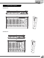
Front & Rear Panels .................................................. 8
Channel Control Block....................................... 10
Master Control Block ......................................... 13
Rear Input/Output Block .................................... 19
Appendix ................................................................. 22
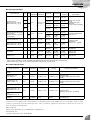
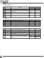
Specifications .................................................... 22
Dimensional Diagrams....................................... 25
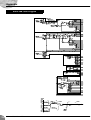
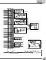
Block and Level Diagram ................................... 26
Features Contents

Introduction
MG32/14FX, MG24/14FX
7
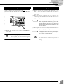
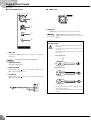
(1) Be sure that the mixer’s power switch is off ( ).
(2) Connect the socket end of the power cord to the AC IN connec-
tor on the rear of the mixer.
(3) Plug the other end of the power cord into a standard household
power outlet.
Be sure to unplug the power cord from the outlet if
you are not going to use the mixer again for an
extended period, and whenever there are lightning
storms in the area.
(1) Before connecting to microphones and instruments, be sure
that all devices are turned off. Also be sure that all of the
mixer’s channel faders and master control faders are set all the
way down.
(2) For each connection, connect one end of the cable to the rele-
vant microphone or instrument and connect the other end to the
appropriate input jack on the mixer.
On each monaural channel, you may use either
INPUT A or INPUT B, but not both. On stereo chan-
nels that provide both a phone input jack and an
RCA-pin input jack, you may use either of these but
not both. Please connect to only one of these jacks
on each channel.
(3) Power up the devices in the following order: Peripheral devices
→ mixer → power amps (or powered speakers).
When shutting the system down, turn off the power
in the opposite order: Power amps (powered speak-
ers) → mixer → peripheral devices.
Do not block the vents. Vent holes are located on the
top, bottom, front, rear, and sides of this machine. All
vent holes must remain unblocked to prevent over-
heating.
Connecting to Power Setting Up
NOTE
NOTE

MG32/14FX, MG24/14FX
8
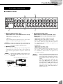
Front & Rear Panels
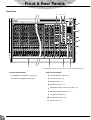
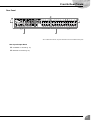
Front Panel
Note: Within this manual, all panel illustrations show the MG32/14FX panel.
11
8
10
342
7
6 5
1
9
8
Channel Control Block Master Control Block
1
MONAURAL CHANNELS Section (p. 10)
3
STEREO/MONO Section (p. 13)
2
STEREO CHANNELS Section (p. 10)
4
GROUP Section (p. 14)
5
SEND Section (p. 14)
6
RETURN Section (p. 15)
7
INTERNAL DIGITAL EFFECTS Section (p. 16)
8
METER/PHONES Section (p. 17)
9
2TR INPUT Section (p. 17)
10
TALKBACK Section (p. 18)
11
LAMP Jack (p. 18)


Front & Rear Panels
MG32/14FX, MG24/14FX
10
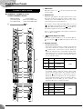
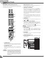
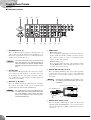
■ MONAURAL CHANNELS Section
STEREO CHANNELS Section
1 PAD Switch
When this switch is on ( ), the mixer attenuates the input
signal by 26 dB.
2 GAIN Control
Adjusts the gain applied to the input signal level. To get the
best balance between the S/N ratio and the dynamic range,
adjust the gain so that the PEAK indicator (B) comes on just
as the signal approaches its maximum level.
On monaural channels: When the PAD switch (1) is off
( ), the GAIN control adjusts for input levels from –60 dBu
to –16 dBu. When the PAD switch is on ( ), the GAIN con-
trol adjusts for input levels from –34 dBu to +10 dBu.
On stereo channels: The GAIN control adjusts for input levels
from –34 dBu to +10 dBu.
3 Switch (High-Pass Filter)
This switch toggles the HPF on or off. To turn the HPF on,
press the switch in ( ). The HPF cuts frequencies below 80
Hz.
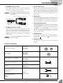
4 Equalizer Controls
• On monaural channels
A three-band equalizer adjusts the channel’s high, mid, and
low frequency bands. For each band, setting the knob to the
position produces a flat frequency response. Turning the
knob to the right boosts the corresponding frequency band,
while turning to the left cuts the band. The following table
shows the EQ type, base frequency, and maximum cut/boost
for each of the three bands.
• On stereo channels
A four-band equalizer adjusts the channel’s high, hi-mid,
lo-mid, and low frequency bands. For each band, setting the
knob to the position produces a flat frequency response.
Turning the knob to the right boosts the corresponding fre-
quency band, while turning to the left cuts the band. The fol-
lowing table shows the EQ type, base frequency, and
maximum cut/boost for each of the four bands.
Channel Control Block
1
2
3
4
7
6
8
9
0
A
B
C
D
E
F
55
G
Monaural Channels
1 to 24 (MG32/14FX)
1 to 16 (MG24/14FX)
Stereo Channels
25/26 to 31/32 (MG32/14FX)
17/18 to 23/24 (MG24/14FX)
Band Type Base Frequency Maximum Cut/Boost
HIGH Shelving 10 kHz
±15 dBMID Peaking
250 Hz to 5 kHz
(variable)
LOW Shelving 100 Hz
Band Type Base Frequency Maximum Cut/Boost
HIGH Shelving 10 kHz
±15 dB
HI-MID Peaking 3 kHz
LO-MID Peaking 800 Hz
LOW Shelving 100 Hz

Front & Rear Panels
MG32/14FX, MG24/14FX
11
5 AUX Controls (AUX1 to AUX6)
These knobs adjust the channel’s signal levels into AUX buses
1 to 6. Each knob controls the signal into the corresponding
AUX bus.
For AUX1 to AUX4, you use the PRE switch (6) to select
whether the pre-fader or post-fader signal is fed to the bus. For
AUX5 and AUX6, only the post-fader signal can be fed.
These knobs should generally be set close to the position.
On stereo channels, the L (odd) and R (even) input signals are
mixed before moving into the AUX bus.
To enable use of AUX5 and AUX6, you must turn on
the AUX5/AUX6 switch (
8).
6 PRE Switch
Selects whether the pre-fader or the post-fader signal is fed to
the corresponding pair of AUX buses. The upper PRE switch
controls the signal to AUX1 and AUX2; the lower switch con-
trols the signal to AUX3 and AUX4. If the switch is on ( ),
the mixer feeds the pre-fader signal to the corresponding buses.
If off ( ), the mixer feeds the post-fader signal.
There is no PRE switch for AUX5 and AUX6. For
these buses only the post-fader signal is available.
7 EFFECT Controls
These knobs adjust the channel’s signal levels into EFFECT
buses 1 and 2. Since the signal to the EFFECT buses is
post-fader, the level is always determined by the combination
of the EFFECT control and the channel fader.
On stereo channels, the L (odd) and R (even) input signals are
mixed before moving into the EFFECT bus.
These knobs operate as EFFECT controls only if
the AUX5/AUX6 switch is in off position ( ). If the
switch is on, these knobs adjust the output to the
AUX5 and AUX6 buses. (See
8 below.)
8 AUX5, AUX6 Switch
Selects whether the channel signal is sent to AUX buses 5 and
6 or EFFECT buses l and 2. If the switch is on ( ), the signal
goes to AUX5 and 6 buses; if off ( ), the signal goes to the
EFFECT buses. Note that the signal to these buses is always
post-fader.
9 PAN Control (Monaural Channels)
BAL Control (Stereo Channels)
The PAN control adjusts the signal’s pan positioning into the
Group 1-2 bus pair, into the Group 3-4 bus pair, and into the
Stereo bus’s L and R lines.
The BAL control knob sets the balance between left and right
channels. Signals into the L input (odd channel) feed to the
Group 1 and Group 3 buses and to the L line of the Stereo bus.
Signals into the R input (even channel) feed to the Group 2 and
Group 4 buses and to the R line of the Stereo bus.
If you are inputting to a stereo channel through the
L (MONO) jack only, the BAL knob operates as a
PAN knob.
0 ON Switch
Sets the channel on or off. To turn the channel on, press the
switch in ( ) so that it lights up orange. Be sure to turn on all
the channels that you wish to use. If you set the channel off
( ), you cut off all of its signal feed into the ST, GROUP,
AUX, and EFFECT buses.
• The ON switch does not affect the operation of
the PFL switch (A). You can monitor the chan-
nel’s pre-fader signal through the PHONES jack
even when the ON switch is set off.
•To reduce noise, turn all unused channels off
().
A PFL (Pre-Fader Listen) Switch
Use this switch to feed the channel’s pre-channel-fader signal
into the PFL bus, so that you can monitor the signal from the
PHONES jack. To turn PFL feed on, press the switch in ( )
so that it lights up.
• If you switch on output to both the PFL and AFL
buses, the mixer outputs only the PFL signal.
• If you set PFL on for multiple channels, the mixer
feeds the mixed signal from the channels into the
PFL bus.
B PEAK indicator
Lights up when the channel’s post-equalizer signal level comes
within 3 dB of the clipping level.
C SIGNAL indicator
Lights up when a signal is being input into the channel.
D GROUP Switches
Use these switches to feed the channel’s signal to the GROUP
1-2 and/or GROUP 3-4 buses. Setting the switch on ( )
causes the signal to feed into the corresponding GROUP buses.
These switches allow you to independently assign
the signal to groups regardless of the setting of the
ST switch (E).
E ST Switch
Set this switch on ( ) to feed the channel’s signal to the ST
bus.
F Channel Fader
Adjusts the output level of the channel’s signal. Use these fad-
ers to adjust the volume balance among the various channels.
To reduce noise, set the fader sliders for unused
channels all the way down.
NOTE
NOTE
NOTE
NOTE
NOTE
NOTE
NOTE
NOTE

Front & Rear Panels
MG32/14FX, MG24/14FX
12
G PHANTOM +48 V Switch
Toggles phantom power on or off to a set of eight adjacent
channels. The MG32/14FX has three of these switches: for
CHs 1 to 8, for CHs 9 to 16, and for CHs 17 to 24. The
MG24/14FX has two: for CHs 1 to 8 and for CHs 9 to16. If
using condenser microphones, set the switch on ( ) for all
channels to which these microphones are connected.
If this switch is on ( ), the mixer supplies DC
+48 V power to pins 2 and 3 of all XLR-type jacks in
the corresponding channels.
• Be sure to leave these switches off ( ) if you do
not need phantom power. Humming or damage
may result if you connect to an unbalanced device
or to an ungrounded transformer while this switch
is on ( ). But note that the switch may be left on
without problem when connecting to balanced
dynamic microphones.
• To avoid damage to speakers, be sure to turn off
amplifiers (or powered speakers) before turning
these switches on or off.
Monaural channels
Stereo channels
NOTE

Front & Rear Panels
MG32/14FX, MG24/14FX
13
■ STEREO/MONO Section
You use this section to independently adjust the levels of the out-
puts from the ST bus. You can independently adjust the main stereo
output, the sub stereo output, and the mixed monaural output.
1 ST SUB OUT Control
Adjusts the level of the signal that feeds from the ST bus into
the ST SUB OUT jack (8 on page 20).
This control has no effect on the output level to the
ST OUT jacks.
2 AFL (After-Fader Listen) Switch
Feeds the signal that is going to the ST OUT and MONO jacks
into the AFL bus, so that this signal can be monitored at the
PHONES jack.
3 ST Master Fader
Adjusts the level of the signal that feeds from the ST bus into
the ST OUT jacks (9 on page 20).
4 MONO Fader
Adjusts the level of the signal that feeds from the ST bus into
the MONO output jack (0 on page 20).
5 LPF (MONO)
• LPF Switch
Set this switch ON to apply a low-pass filter to the signal out-
put from the MONO output jack, or OFF to turn this LPF off.
If the switch is ON, the LPF will cut frequencies that are
above the cutoff set by the Frequency Adjustment dial.
•Frequency Adjustment Dial
Adjusts the cutoff frequency for the LPF. The adjustment
range is 80 Hz to 120 Hz. This dial is effective only if the
LPF switch is set to ON.
Use a straight screwdriver or something similar to
turn the dial.
Master Control Block
2
1
5
34
NOTE
NOTE

Front & Rear Panels
MG32/14FX, MG24/14FX
14
■ GROUP Section
This section adjusts the level and controls the flow of the signals
from the four GROUP buses. While the signal from each GROUP
bus is always fed into the corresponding GROUP OUT jack (see
page 20), you are also free to use the TO ST and AFL switches to
selectively feed these groups into the ST and AFL buses.
1 PAN Control
If you are feeding the signal from the GROUP bus into the ST
bus (that is, if the corresponding TO ST switch (
2) is on), this
knob controls how the signal is positioned on the ST L/R lines.
2 TO ST Switches
For each group: If the switch is on ( ), the mixer feeds the
signal from the GROUP bus into the ST bus, after first passing
the signal through the GROUP fader (
4) and the PAN control
(
1).
3 AFL (After-Fader Listen) Switches
Feeds the corresponding GROUP OUT signal into the AFL
bus, so that this signal can be monitored at the PHONES jack.
4 Group Faders
Each fader adjusts the level of the signal that is fed to the corre-
sponding GROUP OUT jack.
■ SEND Section
This section adjusts the levels and controls the flow of the signals
from the six AUX buses and the two EFFECT buses. Each of these
signals flows to the corresponding SEND output jack (to
AUX1–AUX6, EFF1, and EFF2, respectively).
1 AUX Controls (AUX1 to AUX6)
Each knob adjusts the level of the signal from the indicated
AUX bus into the corresponding AUX SEND jack.
2 Effect Controls (EFF1, EFF2)
Each knob adjusts the level of the signal from the indicated
EFFECT bus into the corresponding EFFECT SEND jack and
also into the corresponding internal digital effect.
For each channel, you use the channel’s AUX5/6
switch (see page 11) to select between feed into the
AUX5 and 6 buses or feed into the EFFECT 1 and 2
buses. If the switch is on ( ), the signal goes to
the AUX5 and AUX6 SEND jacks. If the switch is off
( ), the signal goes to the EFF1 and EFF2 SEND
jacks.
3 AFL (After-Fader Listen) Switches
For each AUX and EFFECT bus: Use this switch to feed the
corresponding AUX SEND or EFF SEND signal into the AFL
bus. Feeds the corresponding AUX SEND or EFF SEND signal
into the AFL bus, so that this signal can be monitored at the
PHONES jack.
If you set this switch on for EFF1 or EFF2, you can
use the PHONES jack to monitor the signal to the
corresponding internal digital effect.
1
2
3
4
3
1
2
NOTE
NOTE

Front & Rear Panels
MG32/14FX, MG24/14FX
15
■ RETURN Section
This section adjusts the levels of the input from the RETURN 1 and
RETURN 2 jacks (see page 20). For each RETURN, you can set
independent levels for feeds into the ST bus and AUX buses 1 to 4.
1 AUX Mix Controls (1 to 4)
Each knob adjusts the level of the signal from the correspond-
ing RETURN jack into the corresponding AUX bus (AUX1 to
AUX4). If you are inputting a stereo signal, the L and R signals
are mixed before moving to the AUX buses.
2 ST Control
Adjusts the level of the signal from the corresponding
RETURN jack into the ST bus. If you are inputting a stereo
signal, the L signal goes into the ST L line and the R signal
goes into ST R line. If you are inputting a mono signal, the
same signal is fed to both ST L and ST R.
3 PFL (Pre-Fader Listen) Switch
Use this switch to feed the corresponding RETURN signal,
taken from before the ST and AUX Mix controls, into the PFL
bus, so that you can monitor the signal at the PHONES jack. To
turn the PFL feed on, press the switch in ( ).
3
2
1
3
2
1

Front & Rear Panels
MG32/14FX, MG24/14FX
16
■ INTERNAL DIGITAL EFFECTS Section
You use this section to control the dual internal effects processor: to
select the two effect types, to set the effects on or off, and to adjust
the related signal levels and flows.
1 PROGRAM Dials
This dial sets the effect type for the corresponding internal dig-
ital effect. For information about the effect types, see page 24.
2 PARAMETER Controls
This knob sets the parameter value for the corresponding inter-
nal digital effect. The setting applies to the currently selected
effect type.
The mixer saves the last value used with each effect
type. When you change to a different effect type, the
mixer automatically restores the value that was pre-
viously used with the newly selected effect (regard-
less of the current position of the Parameter Control
knob). These parameter values are retained even
after power-off.
3 AUX PRE Controls (1 to 4)
Each knob adjusts the level of the effected sound into the corre-
sponding AUX bus (AUX1 to AUX4).
4 TAP Button and Indicator
This feature lets you set the delay time for internal EFFECT 2
by tapping on the button. The feature only works if you have
set the effect type for EFFECT 2 to [16] TAP DELAY. To set
the delay time, tap on the button at the appropriate interval. The
mixer measures the interval between the last two taps and sets
this as the delay time. Continue tapping as necessary until you
get the timing right.
The mixer retains the last time setting even after power goes
off, and restores this setting the next time you set the effect
type to TAP DELAY. The indicator next to the button flashes in
sync with the delay time.
5 ON Switches
This switch turns the corresponding internal digital effect on
() or off ( ).
6 PFL (Pre-Fader Listen) Switches
Use this switch to feed the corresponding digital effect signal,
taken from before the EFFECT RTN fader, into the PFL bus, so
that you can monitor the signal from the PHONES jack. To
turn the PFL feed on, press the switch in ( ).
The signal will not feed into the PFL bus if the
effect’s ON switch (5) is turned off.
7 GROUP Switches
Set the switch on ( ) to feed the corresponding internal digi-
tal effect signal into the corresponding GROUP buses. The top
button feeds the signal to Groups 1 and 2; the lower button
feeds it to Groups 3 and 4.
8 ST Switches
Set this switch on to feed the corresponding internal digital
effect signal into the ST bus.
9 EFFECT RTN faders (1, 2)
This fader adjusts the level of the effected sound into the ST
and GROUP buses.
1
5
6
7
8
2
3
4
9
NOTE
NOTE

Front & Rear Panels
MG32/14FX, MG24/14FX
17
■ METER/PHONES Section
You use these meters to view various signal levels: the levels to the
ST OUT jacks, the PFL and AFL levels, and the levels to the
GROUP OUT jacks. The PFL or AFL signals indicated by these
meters can be monitored through the PHONES jack.
1 POWER Indicator
Lights up when the mixer’s power is on.
2 STEREO Level Meters
If the GROUP switch (4) is off, the left and right meters show
the level to the ST OUT L and R jacks, respectively. If the
GROUP switch is on, the left and right meters show the level to
GROUP OUT jacks 1 and 2, respectively. The “0” position cor-
responds to the standard level. The PEAK indicator lights up
red when the level hits the clipping point.
3 PFL-AFL Level Meters
If the GROUP switch (4) is off, these meters show the levels
to the PHONES jack. If the GROUP switch is on, the left meter
shows the level to GROUP OUT jack 3 and the right meter
shows the level to GROUP OUT jack 4. The “0” position corre-
sponds to the standard level. The PEAK indicator comes on red
when the level hits the clipping point.
If signals are present on both the PFL and AFL
buses, the PHONES jack will output the PFL signal
only. Accordingly, these meters will indicate only the
PFL level.
4 GROUP Switch
Selects whether the meters show the GROUP levels or the ST
and PFL/AFL levels. If the switch is on ( ), the four meters
show the levels to GROUP OUT jacks 1 to 4, in order. If the
switch is off ( ), the meters operate as described above.
5 PHONES Jack and Control
• PHONES Jack
An unbalanced stereo phone output jack, for connection to
headphones.
• PHONES Control
Controls the level of the signal output to the PHONES jack
for monitoring.
The PFL-AFL level meter (3) shows the level of the
signal monitored through the PHONES jack.
■ 2TR INPUT Section
This section adjusts the signal that is input from the 2TR IN jack
(see page 20).
1 2TR IN Control
Adjusts the level of the signal from the 2TR IN jack into the ST
bus.
2 PFL (Pre-Fader Listen) Switch
Use this switch to feed the signal from the 2TR IN jack, taken
from before the 2TR IN control, into the PFL bus, so that you
can monitor the signal from the PHONES jack. To turn the PFL
feed on, press the switch in ( ).
3
4
2
1
5
NOTE
NOTE
1
2

Front & Rear Panels
MG32/14FX, MG24/14FX
18
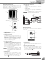
■ TALK BACK Section
1 MIC Jack
An unbalanced XLR input jack, for connection to a talkback
microphone.
This jack does not supply phantom power.
2 Talkback Control
Adjusts the talkback level.
3 AUX1-4 Switch
If this switch is on ( ), the mixer feeds the signal from the
MIC jack into AUX buses 1 to 4.
4 ST Switch
If this switch is on ( ), the mixer feeds the signal from the
MIC jack to the ST bus.
■ LAMP Jack
LAMP Jack
An XLR3 pin-type output jack, for connection to a lamp.
Supported lamps: 12V (AC or DC), max. 5W.
Supplies 12V to Pins 2 and 3. Pin 1 is not con-
nected.
1
2
3
4
NOTE
IMPORTANT: Please read carefully before con-
necting a lamp.
• Do not use a lamp that grounds Pin 2 or Pin 3 to the
shell (body).
Use of the wrong lamp type may result in damage
to the mixer.
Recommended lamps: Littlite's X-HI series of goose-
neck lamps.
• Do not inadvertently connect a talkback micro-
phone to the LAMP jack.
A microphone may sustain damage if connected to
this jack.
NOTE
Wrong lamp type
12
3
12
3
Correct lamp type
12
3
Shell

Front & Rear Panels
MG32/14FX, MG24/14FX
19
L
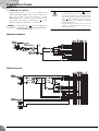
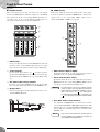
■ CHANNEL I/O Section
1 Monaural-Channel Input Jacks
(MG32/14FX: CHs 1 to 24, MG24/14: CHs 1 to 16)
• INPUT A
These are balanced XLR input jacks.
• INPUT B
These are balanced phone input jacks. You can connect either
balanced or unbalanced phone plugs to these jacks.
On any given channel, you may use either INPUT A
or INPUT B, but not both. If you connect to both of
these inputs, only INPUT B will be effective.
2 INSERT I/O Jacks
These are unbalanced TRS (tip, ring, sleeve) phone-type bidi-
rectional jacks. You can use these jacks to connect channels to
devices such as graphic equalizers, compressors, and noise fil-
ters.
Connection to an INSERT I/O jack requires a spe-
cial separately-sold insertion cable such as illus-
trated below.
3 Stereo-Channel Input Jacks
(MG32/14FX: CHs 25/26, 27/28, 29/30, 31/32)
(MG24/14FX: CHs 17/18, 19/20, 21/22, 23/24)
• Phone jacks
(MG32/14FX: CHs 25/26, 27/28, 29/30, 31/32)
(MG24/14FX: CHs 17/18, 19/20, 21/22, 23/24)
These are unbalanced phone input jacks. You can use each
pair of jacks to input a stereo signal. Feed the L signal into
the odd-numbered channel, and the R signal into the
even-numbered channel.
• RCA-pin jacks
(MG32/14FX: CHs 29/30, 31/32)
(MG24/14FX: CHs 21/22, 23/24)
These are unbalanced RCA-pin input jacks. You can use each
pair of jacks to input a stereo signal. Feed the L signal into
the odd-numbered channel, and the R signal into the
even-numbered channel.
• Where a channel provides both a phone jack and
an RCA pin jack, you may use either one of these
jacks but you may not use both at the same time.
Please connect to only of these jacks on each
channel.
• Some of the phone jacks (MG32/14FX: CHs
25/26, 27/28; MG24/14FX: CHs 17/18, 19/20)
also support monaural input. Specifically, if you
input only into the L (MONO) jack of either pair
(while leaving the R jack empty), the mixer will
propagate the same signal through both the L
(MONO) and R inputs.
Rear Input/Output Block
2
13
NOTE
NOTE
To the INSERT I/O jack
To the input jack of the external processor
To the output jack of the external processor
Ring
Sleeve
Tip
Sleeve
Tip
NOTE

Front & Rear Panels
MG32/14FX, MG24/14FX
20
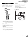
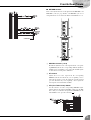
■ MASTER I/O Section
1 RETURN Jacks (1, 2)
These are unbalanced phone input jacks. The signal into each
of these jacks feeds into the ST bus and into AUX buses 1 to 4.
These jacks are typically used to receive a return signal from an
external effector (reverb, delay, etc.).
These jacks can also be used as an auxiliary stereo
input. If you connect to the L (MONO) jack only, the
mixer will recognize the signal as monaural and will
propagate the identical signal from both L and R
jacks.
2 2TR IN Jacks
These unbalanced RCA-pin input jacks can be used to input a
stereo sound source. The signal into each of these jacks feeds
into the ST bus. Use these jacks when you want to connect a
stereo sound source (such as a CD player or DAT deck) directly
to the mixer for monitoring.
3 REC OUT (L, R) Jacks
These are unbalanced RCA-pin output jacks. By connecting
these jacks to an external recorder, you can record the same
signal that is being output from the ST OUT jacks.
The signal from these jacks is not adjusted by the
ST master fader and is not affected by input or out-
put at the INSERT I/O jacks. When using these
jacks to record, adjust the level as necessary at the
external recording device.
4 SEND Jacks
•AUX Jacks (1 to 6)
These are impedance-balanced phone jacks. These jacks out-
put the signals from AUX1 to AUX6, respectively. You use
these jacks, for example, to connect to a monitoring system,
effector, or other such equipment.
• EFFECT Jacks (1, 2)
These impedance-balanced phone jacks output the signals
from the EFFECT buses. You would typically use these jacks
to connect to an external effector.
5 GROUP INS I/O Jacks (1 to 4)
These are unbalanced TRS (tip, ring, sleeve) phone-type bidi-
rectional jacks. You can use these jacks to connect individual
groups to devices such as graphic equalizers, compressors, and
noise filters.
Connection to an INSERT I/O jack requires a spe-
cial separately-sold insertion cable such as illus-
trated below.
6 GROUP OUT Jacks (1 to 4)
These are impedance-balanced phone output jacks. These jacks
output the signals from GROUP buses 1 to 4. Use these jacks to
connect to the input jacks of MTRs, external mixers, and other
such devices.
BA87 1
2345690C
NOTE
NOTE
NOTE
To the INSERT I/O jack
To the input jack of the external processor
To the output jack of the external processor
Ring
Sleeve
Tip
Sleeve
Tip
Strona się ładuje...
Strona się ładuje...
Strona się ładuje...
Strona się ładuje...
Strona się ładuje...
Strona się ładuje...
Strona się ładuje...
Strona się ładuje...
-
 1
1
-
 2
2
-
 3
3
-
 4
4
-
 5
5
-
 6
6
-
 7
7
-
 8
8
-
 9
9
-
 10
10
-
 11
11
-
 12
12
-
 13
13
-
 14
14
-
 15
15
-
 16
16
-
 17
17
-
 18
18
-
 19
19
-
 20
20
-
 21
21
-
 22
22
-
 23
23
-
 24
24
-
 25
25
-
 26
26
-
 27
27
-
 28
28


Yamaha MG24 Instrukcja obsługi
- Kategoria
- Sprzęt muzyczny
- Typ
- Instrukcja obsługi
w innych językach
- čeština: Yamaha MG24 Uživatelský manuál
- español: Yamaha MG24 Manual de usuario
- italiano: Yamaha MG24 Manuale utente
- Deutsch: Yamaha MG24 Benutzerhandbuch
- svenska: Yamaha MG24 Användarmanual
- português: Yamaha MG24 Manual do usuário
- français: Yamaha MG24 Manuel utilisateur
- Türkçe: Yamaha MG24 Kullanım kılavuzu
- English: Yamaha MG24 User manual
- dansk: Yamaha MG24 Brugermanual
- русский: Yamaha MG24 Руководство пользователя
- suomi: Yamaha MG24 Ohjekirja
- Nederlands: Yamaha MG24 Handleiding
- română: Yamaha MG24 Manual de utilizare
Powiązane artykuły
-
Yamaha MGP24X Instrukcja obsługi
-
Yamaha IM8 Instrukcja obsługi
-
-
Yamaha MG16XU Instrukcja obsługi
-
Yamaha MG12XU Instrukcja obsługi
-
-
-
-
-