Kessel 016-839 Connect Pro LTE Module Installation and Operating Instructions
- Typ
- Installation and Operating Instructions

DE: Connect Pro LTE Modul (Art.-Nr. 72300)
WARNUNG
Spannungsführende Teile!
Elektrische Komponenten dürfen nur von einer Elektrofachkraft montiert oder demontiert werden.
Nach dem Tausch von Komponenten muss eine Sicherheitsprüfung (Sichtprüfung, Funktions- und Fehlerstromprüfung, etc.) nach
nationalen Vorschriften für elektrische Sicherheit durchgeführt werden.
Der Anlage und dem Schaltgerät beiliegende Dokumentation beachten.
Technische Hinweise
Die LTE Platine ermöglicht den drahtlosen Datentransfer zwischen dem Schaltgerät und der Signalweiterleitung auf bis zu drei Mobiltelefone bzw. die
Datenübermittlung (TCP) in ein Portal bzw. eine Cloud. Voraussetzung ist ein stabiler und ausreichender Zugang zum Mobilfunknetz.
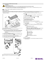
LTE Platine montieren
Schaltgerätedeckel öffnen.
Blindstopfen von der Schaltgeräteunterseite entfernen.
Für die Aufsteckplatinen ist eine Position zwischen Display und
Anschlussklemmen vorgesehen. Die Position ist begrenzt durch
zwei Öffnungen sowie der Fassung für den Stecker der Auf-
steckplatine.
Den Platine-Abstandshalter in die beiden, dafür vorgesehenen, Öff-
nungen der Grundplatine einsetzen .
Die LTE Platine so ausrichten, dass der Stecker über der roten Auf-
nahme liegt (Seite mit QR-Code-Aufkleber nach oben).
Danach die LTE Platine auf die Abstandshalter und die rote Auf-
nahme festdrücken, bis sie einrastet .
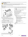
Gewinde der Kabelverschraubung M16x1,5 eindrehen .
Antennenkabel durch die Kabelverschraubung fädeln .
Beide Hülsenteile über dem Messing-Endstück zusammenfü-
gen .
Mutter der Kabelverschraubung festziehen, Anzugsdrehmoment
von 1 Nm beachten .
Adapter aufschrauben (Sechskantseite voraus) .
Antenne auf Adapter schrauben .
Schaltgerätedeckel schließen.
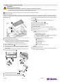
LTE Kommunikationstyp einstellen
Stromanschluss herstellen.
Schaltgerät gemäß Initialisierungsdialog konfigurieren.
Zum Menüpunkt |Kommunikation| navigieren und das Passwort
„1000“ eingeben.
Dort zum Menü |Kommunikationstyp| navigieren und den
gewünschten Kommunikationstyp (SMS oder Daten) auswählen.
SMS:
Stationsname: (optional)
PIN: von der verwendeten SIM-Karte
SMS- Ziel 1, SMS-Ziel 2 und SMS- Ziel 3: Empfänger defi-
nieren. Diese Option erlaubt bis zu 3 Empfänger.
Folgende beliebige Auswahl ist für den Benutzer zur Verfü-
gung:
Fehler: Ein/Aus
Ereignis: Ein/Aus
Betr. Std: Ein/Aus
Status: Ein/Aus
Scan: Ein/Aus
Status: zeigt die Netzverfügbarkeit.
Daten:
Mit „OK“ bestätigen.
Anschließend prüfen, ob die Übermittlung erfolgreich und die Ver-
bindung stabil ist.
016-839 Vers.: 01 2023/12

EN: Connect Pro LTE module (art. no. 72300)
WARNING
Live parts!
Electrical components may only be mounted or dismantled by an electrically skilled person.
After replacing components, a safety check (visual inspection, functional and residual current test, etc.) must be carried out according
to the national regulations for electrical safety.
Note and follow the documentation enclosed with the system and control unit.
Technical notes
The LTE printed circuit board enables wireless data transfer between the control unit and forwarding signal to up to three mobile phones or the data
transfer (TCP) to a portal or cloud. This requires stable and sufficient access to a mobile network.
Mounting the LTE printed circuit board
Open the control unit cover.
Remove the blind plugs from the underside of the control unit.
A position is provided for the plug-in printed circuit boards
between the display and connection terminals. The position is
limited by two openings as well as the socket for the printed cir-
cuit board connector.
Insert the printed circuit board spacer in the two openings provided
for it in the motherboard .
Align the LTE printed circuit board so that the connector is posi-
tioned above the red retainer (side with the QR code sticker facing
upwards).
Then push the LTA printed circuit board firmly onto the spacer and
the red retainer until it latches into position .
Screw in the thread of the cable gland M16x1.5 .
Thread the antenna cable through the cable gland .
Join both sleeve parts above the brass end piece .
Tighten the nut of the cable gland with a torque of 1 Nm .
Screw on the adapter (hexagonal side at the front) .
Screw the antenna onto the adapter .
Close the control unit cover.
Setting the LTE communication type
Connect to the power supply.
Configure the control unit as instructed in the initialisation dialog.
Navigate to the |Communication| menu item and enter the pass-
word „1000“.
Navigate there to the |Communication type| menu and select
the desired communication type (SMS or data).
SMS:
Station name: (optional)
PIN: Used by the SIM card
SMS- Destination 1, SMS-Destination 2 and SMS-Desti-
nation 3: Define the recipient. This option permits up to 3
recipients.
The following random selection is available for the user:
Error: On/Off
Event: On/Off
Operating hours: On/Off
Status: On/Off
Scan: On/Off
Status: Shows the network availability.
Data:
Confirm with „OK“.
Then check whether the transfer has been successful and the con-
nection is stable.
839-016 Vers.: 01 12/2023

FR: Module Connect Pro LTE (réf. 72300)
AVERTISSEMENT
Pièces sous tension !
L’installation et le démontage des composants électriques relèvent du domaine de compétence d’un électricien.
Le remplacement des composants doit être suivi d’un contrôle de sécurité (contrôle visuel, contrôle du fonctionnement et des courants
de court-circuit, etc.) aux termes des prescriptions nationales en matière de sécurité électrique.
Observer la documentation jointe au système et au gestionnaire.
Remarques techniques
La platine LTE permet un transfert de données sans fil entre le gestionnaire et la transmission de signaux vers jusqu’à trois téléphones mobiles ou la
transmission de données (TCP) vers un portail ou un cloud. Pour cela, il convient d'avoir un accès stable et suffisant au réseau de téléphonie mobile.
Monter la platine LTE
Ouvrir le couvercle du gestionnaire.
Retirer le bouchon de la face inférieure du gestionnaire.
Une position entre l'écran et les bornes de raccordement est
prévue pour les platines enfichables. La position est limitée par
deux ouvertures, ainsi que par la douille de la fiche de la platine
enfichable.
Insérer les entretoises de la platine dans les deux ouvertures de la
platine de base prévues à cet effet .
Orienter la platine LTE de manière à ce que la fiche se trouve au-
dessus du logement rouge (côté comportant l'autocollant du QR
Code vers le haut).
Appuyer ensuite fermement sur la platine LTE sur les entretoises et
le logement rouge jusqu'à ce qu'elle s'enclenche .
Visser le filetage du presse-étoupe M16x1,5 .
Faire passer le câble d'antenne à travers le presse-étoupe .
Assembler les deux parties de la douille au-dessus de l'embout en
laiton .
Serrer l'écrou du presse-étoupe, observer un couple de serrage de
1 Nm
Visser l’adaptateur (côté hexagonal en avant) .
Visser l’antenne sur l’adaptateur .
Fermer le couvercle du gestionnaire.
Régler le type de communication LTE
Établir l’alimentation électrique.
Configurer le gestionnaire conformément aux indications de la boîte
de dialogue d’initialisation.
Accéder au point de menu |Communication| et saisir le mot de
passe « 1000 ».
Accéder alors au menu |Type de communication| et sélec-
tionner le type de communication souhaité (texto ou données).
Texto :
Nom de l’unité : (en option)
PIN : de la carte SIM utilisée
Destinataire texto 1, destinataire texto 2 et destina-
taire texto 3 : définir les destinataires. Cette option permet
d’avoir jusqu’à 3 destinataires.
L’utilisateur dispose des choix suivants :
Erreur : marche/arrêt
Événement : marche/arrêt
Heures de service : marche/arrêt
Statut : marche/arrêt
Scan : marche/arrêt
Statut : indique la disponibilité du réseau.
Données :
Valider avec OK.
Vérifier ensuite si la transmission a réussi et si la connexion est
stable.
016-839 Vers.: 01 2023/12

IT: Modulo Connect Pro LTE (codice articolo 72300)
AVVERTENZA
Parti conducenti tensione!
I componenti elettrici possono essere montati o smontati solo da un elettricista specializzato.
Dopo la sostituzione dei componenti deve essere eseguito un controllo di sicurezza (controllo visivo, controllo del funzionamento e
delle correnti di guasto, ecc.) ai sensi delle norme nazionali per la sicurezza elettrica.
Prestare attenzione alla documentazione allegata all’impianto e alla centralina.
Avvertenze tecniche
Il circuito stampato LTE permette il trasferimento dei dati senza cavi alla centralina e l’inoltro del segnale a un massimo di tre telefoni cellulari e la tra-
smissione dei dati (TCP) in un portale e/o in un cloud. Il requisito è un accesso stabile e sufficiente alla rete radiomobile.
Montaggio del circuito stampato LTE
Aprire il coperchio della centralina.
Rimuovere il tappo cieco dalla parte inferiore della centralina.
Per il circuito stampato di espansione è prevista una posizione
tra il display e i morsetti di collegamento. La posizione è limitata
da due aperture e dall’alloggiamento per il connettore del cir-
cuito stampato di espansione.
Inserire i distanziatori del circuito stampato nelle due apposite aper-
ture del circuito stampato di base .
Allineare il circuito stampato LTE in modo tale che il connettore si
trovi sopra all’attacco rosso (lato con l’adesivo del codice QR rivolto
verso l’alto).
Successivamente, premere il circuito stampato LTE sui distanziatori
e sull’attacco rosso, fino a farlo scattare in posizione .
Avvitare le filettature del pressacavo M16x1,5 .
Fare passare il cavo dell’antenna attraverso il pressacavo .
Unire le due parti della boccola sul terminale di ottone .
Serrare il dado del pressacavo, rispettando il momento di serraggio
di 1 Nm .
Avvitare l’adattatore (partendo dal lato esagonale) .
Avvitare l’antenna sull’adattatore .
Chiudere il coperchio della centralina.
Impostazione del tipo di comunicazione LTE
Realizzare il collegamento elettrico.
Configurare la centralina seguendo le istruzioni per l’inizializza-
zione.
Andare al punto del menu |Comunicazione| e immettere la pas-
sword “1000”.
Andare quindi al menu |Tipo di comunicazione| e selezio-
nare il tipo di comunicazione desiderato (SMS o dati).
SMS:
Nome stazione: (opzionale)
PIN: della scheda SIM usata
Destinatario SMS 1, destinatario SMS 2 e destinatario
SMS 3: definire i destinatari. Questa opzione permette di
definire fino a 3 destinatari.
Per l’utente è disponibile la seguente selezione libera:
Errore: ON / OFF
Evento: ON / OFF
Ore funzionamento: ON / OFF
Stato: ON / OFF
Scansione: ON / OFF
Stato: mostra la disponibilità della rete.
Dati:
Confermare con “OK”.
Controllare quindi se la trasmissione è riuscita e se la connessione
è stabile.
016-839 Vers.: 01 2023/12

NL: Connect Pro LTE Module (art.nr. 72300)
WAARSCHUWING
Spanningvoerende onderdelen!
Elektrische componenten mogen alleen worden gemonteerd of gedemonteerd door een elektricien.
Na het vervangen van componenten moet een veiligheidsinspectie (visuele inspectie, functionele controle, lekstroomcontrole, enz.) in
overeenstemming met de nationale voorschriften voor elektrische veiligheid worden uitgevoerd.
De bijgevoegde documentatie van de installatie en de besturingskast in acht nemen.
Technische opmerkingen
Met de LTE-printplaat kunnen meldingen van de besturingskast worden doorgegeven aan maximaal drie mobiele telefoons of kunnen gegevens via
TCP aan een online portaal worden doorgegeven. Hiervoor is een stabiele en geschikte toegang tot het mobiele netwerk nodig.
De LTE-printplaat monteren
Open het deksel van de besturingskast.
Verwijder de blindstop van de onderkant van de besturingskast.
Voor de insteekprintplaat is een plek tussen het scherm en de
aansluitklemmen voorzien. Deze plek wordt begrensd door
twee openingen en de fitting van de stekker van de insteekprint-
plaat.
Plaats de afstandshouders voor de printplaat in de beide daarvoor
bedoelde openingen van de grondprintplaat .
Plaats de LTE-printplaat zo, dat de stekker boven de rode houder
ligt (kant met de QR-code boven).
Vervolgens drukt u de LTE-printplaat op de afstandshouders en de
rode houder vast .
Draai de schroefdraad van de kabelschroefverbinding M16x1,5 vast
.
Leid de antennekabel door de kabelschroefverbinding heen .
Zet de beide delen van de huls over het eindstuk van messing
tegen elkaar .
Draai de moer van de kabelschroefverbinding vast met een aan-
draaimoment van 1 Nm .
Schroef de adapter vast (zeskantige zijde naar voren) .
Schroef de antenne op de adapter .
Sluit het deksel van de besturingskast.
Het soort LTE-communicatie instellen
Herstel de stroomaansluiting.
Configureer de besturingskast volgens het dialoogvenster Initialise-
ren.
Ga naar menuonderdeel |Communicatie| en voer het wacht-
woord “1000” in.
Ga daar naar het menu |Soort communicatie| en selecteer de
gewenste soort communicatie (sms of data).
Sms:
Stationsnaam: (optioneel)
Pincode: van de gebruikte simkaart
Sms-doel 1, sms-doel 2, sms-doel 3: de ontvangers
instellen (maximaal drie)
De gebruiker kan de volgende meldingen in- en uitschakelen:
Fouten: aan/uit
Gebeurtenissen: aan/uit
Bedrijfsuren: aan/uit
Status: aan/uit
Scannen: aan/uit
Status: de beschikbaarheid van het mobiele netwerk
Data:
Bevestig met “OK”.
Controleer vervolgens of de communicatie is gelukt en de verbin-
ding stabiel is.
016-839 Vers.: 01 2023 / 12

PL: Moduł Connect Pro LTE (nr art. 72300)
OSTRZEŻENIE
Elementy będące pod napięciem!
Części elektryczne może montować i demontować wyłącznie wykwalifikowany elektryk.
Po wymianie komponentów należy dokonać kontroli bezpieczeństwa (kontrola wzrokowa, kontrola działania i prądu zwarciowego itp.)
zgodnie z krajowymi przepisami dotyczącymi bezpieczeństwa elektrycznego.
Należy przestrzegać dokumentacji dołączonej do urządzenia oraz do urządzenia sterującego.
Wskazówki techniczne
Karta LTE umożliwia bezprzewodowy transfer danych między sterownikiem a urządzeniem do przekazywania sygnału do nawet trzech telefonów
mobilnych lub przekaz danych (TCP) do portalu lub chmury. Warunkiem działania jest stabilny i wystarczający dostęp do sieci telefonii komórkowej.
Montaż karty LTE
Otworzyć pokrywę sterownika.
Wyjąć zaślepkę od spodu sterownika.
Między wyświetlaczem i zaciskami przyłączeniowymi przewi-
dziane jest miejsce na włożenie karty. Pozycja jest ograniczona
przez dwa otwory oraz oprawkę na wtyczkę karty.
Włożyć przekładki karty w obydwa przewidziane do tego celu
otwory w karcie głównej .
Ustawić kartę LTE w taki sposób, aby wtyczka leżała nad czerwo-
nym mocowaniem (by strona z naklejką z kodem QR była skiero-
wana do góry).
Następnie docisnąć kartę LTE do przekładek i czerwonego moco-
wania, aż karta się zatrzaśnie .
Wkręcić dławik kablowy M16x1,5 .
Przeciągnąć kabel anteny przez dławik kablowy .
Połączyć obie części tulei nad miedzianą końcówką .
Dociągnąć nakrętkę dławika kablowego momentem dokręcającym
1 Nm .
Przykręcić adapter (strona sześciokątna skierowana do
przodu) .
Przykręcić antenę do adaptera .
Zamknąć pokrywę urządzenia sterującego.
Ustawienie rodzaju komunikacji LTE
Podłączyć do prądu.
Skonfigurować sterownik zgodnie z dialogiem inicjalizacji.
Przejść do punktu menu |Komunikacja| podać hasło „1000”.
Przejść do menu |Typ komunikacji| i wybrać żądany rodzaj
komunikacji (wiadomość SMS lub dane).
SMS:
Nazwa stacji: (opcjonalnie)
PIN: używanej karty SIM
Cel SMS 1, cel SMS 2 oraz cel SMS 3: określić odbiorcę.
Ta opcja dopuszcza do 3 odbiorców.
Użytkownik ma do wyboru następujące możliwości:
Błąd: wł./wył.
Zdarzenie: wł./wył.
Roboczogodz.: wł./wył.
Status: wł./wył.
Skan: wł./wył.
Status: wskazuje dostępność sieci.
Dane:
Potwierdzić przyciskiem OK.
Następnie należy sprawdzić, czy przekaz zakończył się powodze-
niem, a połączenie jest stabilne.
016-839 Vers.: 01 2023/12
-
 1
1
-
 2
2
-
 3
3
-
 4
4
-
 5
5
-
 6
6


Kessel 016-839 Connect Pro LTE Module Installation and Operating Instructions
- Typ
- Installation and Operating Instructions
w innych językach
- italiano: Kessel 016-839 Connect Pro LTE Module
- Deutsch: Kessel 016-839 Connect Pro LTE Module
- français: Kessel 016-839 Connect Pro LTE Module
- English: Kessel 016-839 Connect Pro LTE Module
- Nederlands: Kessel 016-839 Connect Pro LTE Module