
/ Perfect Welding / Solar Energy / Perfect Charging
QUICK START GUIDE
Fronius Smart Meter TS 5kA-3
42,0410,2495 006-03032022 FRONIUS INTERNATIONAL GMBH www.fronius.com
Detailed, country-specic warranty terms are available on: www.fronius.com/solar/warranty
FIND MORE
INFORMATION
manuals.fronius.com/html/4204260348
SOFTWARE REQUIREMENTS
Fronius Datamanager 2.0 ≥ 3.16.1 version
Fronius Symo Hybrid ≥ 1.16.1 version
MEASURING INPUT
Three-phase nominal voltage range
Operating voltage range
400 - 480 V (-20 % to +15 %)
173 - 400 VLL ± (2 % RDG/accuracy)
Single-phase nominal voltage range
Operating voltage range
230 - 277 V (-20 % to +15 %)
100 - 230 VLN ± (1 % RDG/accuracy)
Voltage transformer ratio (kVT) 1 - 1000 / e. g. VT 20000/400V kVT = 50 / for direct connection: kVT = 1
Protection level 8/20 µs (Up) (star mounting) 4 kV
Current withstand short circuit PV (Iscpv)15000 A
Self-consumption - voltage path (max. voltage) 10 VA
Nominal frequency
Tolerance
50 - 60 Hz
45 - 65 Hz
Nominal current, lb1 A + 5 A
Maximum current, Imax 6 A
Starting current 10 mA
Current transformer ratio (kCT) 1 - 1000
e. g. TC 800/5A kCT = 160
for direct connection: kCT = 1
Short-time overload (EN IEC 62053-21, EN IEC 62053-23) 5 lmax / 0.5 s
Self-consumption - current path (max. current) 0.3 W per phase
Maximum value kVT x kCT 1000 (CT/5A)
Current distortion factor in acc. with EN IEC 62053-21
Power factor Operating range (EN IEC 62053-21, EN IEC 62053-23) active cosφ 0.5 ind - 0.8 cap, reactive sinφ 0.5 ind - 0.5 cap
ENERGY
LED indicator 1 pulse / 0.1 Wh
Active energy accuracy (EN IEC 62053-21) Class 1
Class 2: 100 - 230 VLN (173 - 400 VLL)
Reactive energy accuracy (EN IEC 62053-23) Class 2
Response time after switch-on (EN IEC 62053-21, EN IEC 62053-23) < 5 s
OUTPUT
RS485 communication (Electrically isolated from input and auxiliary voltage)
Standard RS485 - 3 conductors
Protocol Modbus RTU
Addresses 1 - 255
Baud rate 9600, 19200, 38400 bit/s
Response time ≤ 200 ms
INSULATION (EN IEC 62052-11, EN IEC 62053-21)
Installation category III
Degree of pollution 2
Insulation voltage 4 kV RMS
Impulse withstand voltage
Test circuit
4 kV 1.2/60 µs
Voltage input, current input, pulse output, communication
Test voltage
Test circuit
2.75 kV RMS. 50 Hz/1 min
Voltage input, current input, pulse output, communication
Test voltage
Test circuit
4 kV RMS. 50 Hz/1 min
All circuits and earth
ELECTROMAGNETIC COMPATIBILITY
Test in acc. with EN IEC 62052-11
OPERATING CONDITIONS
Reference temperature 25 °C (± 5 °C)
Operating range -25 to +65 °C
Temperature limit for storage and transport -30 to +80 °C
Max. power loss (for thermal dimensioning of the switch cabinet) ≤ 2.8 W
HOUSING
Housing 3 modules according to DIN 43880
Sealable housing/terminal cover
Connection Screw connection
Mounting Can be snapped onto 35 mm DIN rail
Housing material Noryl, self-extinguishing
Degree of protection (EN 60529) IP54 housing, IP20 connections
Weight 240 grams
TERMINALS - MEASURING INPUT
Wire min. 1 mm² / max. 4 mm²
Recommended torque max. 0,6 Nm
TERMINALS - DATA OUTPUT
Wire min 0.05 mm²
Recommended torque max. 0.4 Nm
DE: WARNUNG! Fehlbedienung und fehlerhaft durchgeführte Arbeiten können schwerwiegende Personen- oder
Sachschäden verursachen. Die Installation und Inbetriebnahme des Smart Meters darf nur durch geschultes Personal und
nur im Rahmen der technischen Bestimmungen erfolgen. Vor Arbeiten mit dem Gerät, alle beiliegenden, aufgedruckten
und online zur Verfügung gestellten Dokumente lesen und verstehen! Dieses Dokument beschreibt nicht alle möglichen
Systemkongurationen.
EN: WARNING! Incorrect operation and incorrectly performed work can cause serious personal injury or material damage. The Fronius
Smart Meter may only be installed and commissioned by trained personnel and only within the scope of the technical regulations. Befo-
re working with the device, read and understand all enclosed, printed and online documents! This document does not describe all of the
possible system congurations.
FR: AVERTISSEMENT ! Une mauvaise utilisation et un travail mal eectué peuvent causer des blessures graves ou des dommages
matériels. Le Fronius Smart Meter ne peut être installé et mis en service que par du personnel formé et uniquement dans le cadre des
réglementations techniques. Avant de travailler avec l’appareil, lisez et comprenez tous les documents ci-joints, imprimés et en ligne ! Ce
document ne décrit pas toutes les congurations possibles du système.
IT: ATTENZIONE! Un funzionamento non corretto e un lavoro eseguito in modo non corretto possono causare gravi lesioni personali o
danni materiali. Lo Fronius Smart Meter può essere installato e messo in funzione solo da personale addestrato e solo nell’ambito delle
norme tecniche. Prima di lavorare con l’apparecchio, leggere e comprendere tutti i documenti allegati, stampati e online! Questo docu-
mento non descrive tutte le possibili congurazioni di sistema.
ES: ¡ADVERTENCIA! El funcionamiento incorrecto y el trabajo realizado de forma incorrecta pueden causar graves lesiones personales o
daños materiales. El Fronius Smart Meter sólo puede ser instalado y puesto en marcha por personal capacitado y sólo dentro del ámbito
de los reglamentos técnicos. Antes de trabajar con el dispositivo, lea y entienda todos los documentos adjuntos, impresos y en línea! Este
documento no describe todas las conguraciones posibles del sistema.
DA: ADVARSEL! Forkert betjening og forkert udført arbejde kan forårsage alvorlig personskade eller materielle skader. Fronius Smart
Meter må kun installeres og idriftsættes af uddannet personale og kun inden for rammerne af de tekniske forskrifter. Læs og forstå alle
vedlagte, trykte og online dokumenter, før du arbejder med enheden! Dette dokument beskriver ikke alle mulige systemkongurationer.
PB: ALERTA! Uma operação incorreta e trabalhos mal executados podem provocar graves danos às pessoas e aos equipamentos. A
instalação e o comissionamento do Smart Meter podem ser realizados somente por pessoal treinado e dentro das determinações técnicas.
Antes de trabalhar com o dispositivo, deve-se ler e compreender todos os documentos anexos, impressos e disponíveis online! Os módu-
los solares expostos à luz fornecem tensão ao inversor. Este documento não descreve todas as congurações de sistema possíveis.
PL: OSTRZEŻENIE! Błędy obsługi i nieprawidłowo wykonane prace mogą spowodować poważne obrażenia ciała oraz straty materialne.
Montaż i uruchomienie inteligentnego licznika Fronius Smart Meter mogą zostać wykonane wyłącznie przez przeszkolony personel i
wyłącznie w ramach wymagań technicznych. Przed przystąpieniem do wykonywania prac z urządzeniem należy zapoznać się dokładnie
z treścią wszystkich dokumentów dołączonych do urządzenia, nadrukowanych na nim lub udostępnionych online! Niniejszy dokument
nie opisuje wszystkich możliwych konguracji systemu.

Load / Source
4c
Load / Source
4b
Load / Source
4a
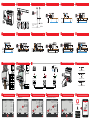
MOUNT THE SMART METER (Step: 2)SWITCH OFF THE CIRCUIT BREAKER (Step: 1) CONNECT THE AUXILIARY POWER SUPPLY (Step: 3) 1 PHASE, 2 WIRES - CT (Step: 4a) 1 PHASE, 2 WIRES - VT/CT (Step: 4b) 2 PHASES, 3 WIRES - CT (Step: 4c)
1 3
L/N/+/-
N/L/-/+
100 - 240 V AC/DC
(± 10%)
2
2 sec. adjust / confirm
1 x page up / value up
1 x page down / value down
98
CONNECT THE DATA CABLES (Step: 5) SET UP THE TERMINATING RESISTOR (Steps: 6-7) NAVIGATE IN THE SETTINGS (Step: 9)
00 1
6
7
Manufacturer manualManufacturer manual
max. 300 m
-
GND
T
D+
M+ M-
D-
Invertere. g. Ohmpilot, Battery Smart Meter
T
5 6
5kA-3
0,4 Nm
CU Wire
0,05 mm²
Bypass (cable)
M-
12
T
10
SWITCH ON THE CIRCUIT BREAKER (Step: 8)
7
Load / Source
4i
Load / Source
4h
Load / Source
4g
3 PHASES, 3 WIRES - CT (Step: 4e)2 PHASES, 3 WIRES - VT/CT (Step: 4d) 3 PHASES, 3 WIRES - VT/CT (Step: 4f) 3 PHASES, 4 WIRES - ARON CT (Step: 4g) 3 PHASES, 4 WIRES - CT (Step: 4h) 3 PHASES, 4 WIRES - VT/CT (Step: 4i)
Load / Source
4d 4f
Load / Source
Load / Source
4e
1
Setup your PV system in a few minutes.
START INSTALLATION
LOGIN
Log in with your Fronius credentials (email adress
& password) in order to get the most out of the
PV System. Installing a new product does not
require a Login.
Imprint & Contac
tT
erms & ConditionsData Privacy
Fronius Solar.start
P18
END
7
8
14
P14
AddrESS
001
PrG
6
5
Factory default: Modbus Address 001
13 START UP THE SMART METER (Step: 15)SETUP THE TRANSFORMATION RATIO (Step: 12)SETUP THE PASSWORD (Step: 11)ENTER THE SETTINGS (Step: 10) SETUP THE ADDRESS (Step: 13) EXIT THE SETTINGS (Step: 14)
0 0
0 0
0 0
L1
L2
L3
kW
1
P4
0010
PrG
4
3
P1
PASS
2633
PrG
2
Factory default: 2633
10 11 12 15
-
 1
1
-
 2
2


w innych językach
- português: Fronius TS 5kA-3 Guia de usuario
- français: Fronius TS 5kA-3 Mode d'emploi
- dansk: Fronius TS 5kA-3 Brugervejledning
Powiązane artykuły

Inne dokumenty
-
Socomec DIRIS A14 Quick Start
-
-
ABB B23 Instrukcja instalacji
-
Circutor CEM-C10 Instrukcja obsługi
-
-
 Lumel ND10 TYPE User Manual & Quick Start
-
ABB B21 Instrukcja instalacji
-
-
-
