
Doc # INT-100147-001
Part No. 191572 Rev. 4
INSTALL INSTRUCTIONS
DTK-110C6A, DTK-110C6APOE
DITEK Technical Support Available 24/7
1-888-472-6100
www.ditekcorp.com
DITEK Corporation
ONE DITEK CENTER
1720 Starkey Road
Largo, FL 33771
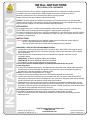
INSTALLATION
This Surge Protective Device (SPD) is a high performance device, designed to provide protection
for sensitive electronic loads when the SPD is directly connected to the electronic device.
Maximum protection will only be achieved if the SPD is properly installed.
Please read and follow the installation instructions carefully.
NOTICE: This SPD should be installed and grounded, by a licensed contractor, per the applicable
requirements of the NEC. These devices are only to be employed on the communication loop circuits
which have been isolated from the Public Switched Telephone Network.
APPLICATION
Surge suppression for IP, or PoE circuits transmitting video and/or data over CAT6 or CAT6A cable.
The DITEK is wired in series and terminating with a 110 punch down Input/Output.
For Power Over Ethernet (PoE) circuits, use DTK-110C6APOE. For non-PoE circuits, use DTK-110C6A.
This device is intended for indoor use or intended for outdoor use within an enclosure which has been
evaluated for the application.
INSTRUCTIONS:
Caution: Measure all voltages to insure applied voltage does not exceed the voltage rating of
the unit. Improper installation voids the warranty.
This unit must be connected in series with the equipment to be protected.
DISCONNECT CIRCUIT BEFORE BEGINNING INSTALL.
1. Connect the incoming (field) wires to the IDC (110) punch down block INPUT side using the proper
punch down tool designed for IDC connectors. Using any other tool will damage the IDC connector
and void warranty.
2. Follow the wire color codes printed on the circuit board next to the IDC connectors for wire
termination points.
T568A Wiring- BL-BL/W, BR-BR/W, OR/W-OR, GR-GR/W
T568B Wiring- BL-BL/W, BR-BR/W, GR/W-GR, OR-OR/W
This connector is rated for 26-22AWG solid conductor wire.
The wire pairs must be twisted together and maintain that twist all the way to the
punch down block.
3. If using STP (Shielded Twisted Pair) , the shield must be connected to the “Shield GND” termination
screw located on the circuit board near the IDC connector. This can be accomplished by twisting
the shield into a wire and wrapping it under the screw.
NOTE: Do not exceed 2 inch/pounds +0/-1 of torque.
4. Using the velcro loops provided, secure the CAT6/CAT6A cabling to the circuit board.
5. Connect the wiring to the equipment to be protected to the IDC (110) punch down block OUTPUT
side using the proper punch down tool designed for IDC connectors. Using any other tool will damage
the IDC connector and void warranty. Repeat steps 2 and 3 above.
6. Always have one common ground per system to eliminate the possibility of a differential in ground
potentials. The ground conductor should be a minimum #14 AWG wire. This wire should be as short
as possible. This wire shall be mechanically secured to the “Ground” termination screw located on the
Input side of the circuit board near the IDC connector.
Ground Resistance Rule: Max ground resistance is 25 Ohms, 5 Ohms or less is optimum.
This cannot be an assumed value and must be measured to assure proper grounding.
7. After all connections have been made and no hazards exist, replace the cover and screws and
restore the circuit.
Drawn By: B. Aycock 6-6-16
Revised By: R. Mitchell 4-27-17

INSTALL INSTRUCTIONS
DTK-110C6A, DTK-110C6APOE
DITEK Technical Support Available 24/7
1-888-472-6100 www.ditekcorp.com
DITEK Corporation
ONE DITEK CENTER
1720 Starkey Road
Largo, FL 33771
INSTALLATION
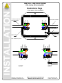
Illustrations Page
Doc # INT-100147-001
Part No. 191572 Rev. 4
Drawn By: B. Aycock 6-6-16
Revised By: R. Mitchell 4-27-17
Note: T568B Wiring Shown
GR / W
OR / W
OR
GR
BL
BL / W
BR
BR / W
SHIELD GND
DTK-110C6A / DTK-110C6APOE
3' MINIMUM LENGTH
GR
OR
OR / W
GR / W
BL / W
BL
BR / W
BR
SHIELD GND
GROUND WIRE
14 AWG MINIMUM
INPUT (FIELD) WIRING
B
B
INPUTOUPUT
TO PROTECTED EQUIPMENT
GR / W
OR / W
OR
GR
BL
BL / W
BR
BR / W
GR
OR
OR / W
GR / W
BL / W
BL
BR / W
BR
B
B
INPUTOUPUT
-
 1
1
-
 2
2


Ditek DTK-110C6APOE Series Instrukcja instalacji
- Typ
- Instrukcja instalacji
- Niniejsza instrukcja jest również odpowiednia dla
w innych językach
Inne dokumenty
-
Eneo VTL-300/WW-POE Installation Instructions Manual
-
Yamaha PM-2000 Instrukcja obsługi
-
Yamaha E3 Instrukcja obsługi
-
Yamaha PLG150 Instrukcja obsługi
-
 Allen-Bradley Stratix 8000 Installation Instructions Manual
-
Yamaha E3 Instrukcja obsługi
-
-
-
Digitus DN-93615 Instrukcja obsługi
-
