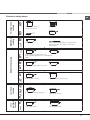
HOTPOINT/ARISTON KRO 632 TD Z instrukcja
- Kategoria
- Płyty
- Typ
- instrukcja
Niniejsza instrukcja jest również odpowiednia dla

GB
1
KRO 632 TD X
KRO 632 TD Z
KRO 642 D B
KRO 642 D X
KRO 642 D Z
KRO 642 TO B
KRO 642 TO X
KRO 642 TO Z
KRO 642 TO B (PL)
KRO 642 D C
KRO 742 DO Z
KRO 742 TO Z

English
GB
Operating Instructions
HOB
Contents
Operating Instructions,1
Description of the appliance-Control Panel,2
Installation,7
Start-up and use,10
Precautions and tips,14
Care and maintenance,15
Technical description of the models,15
FR
Français
Mode d’emploi Manutenção e cuidados
TABLE DE CUISSON
Sommaire
Mode d’emploi,1
Description de l’appareil-Tableau de bord, 2
Installation,16
Mise en marche et utilisation,19
Précautions et conseils, 23
Nettoyage et entretien,24
Description technique des modèles,24
Español
ES
Manual de instrucciones
ENCIMERA
Sumario
Manual de instrucciones,1
Descripción del aparato-Panel de control,2
Instalación,25
Puesta en funcionamiento y uso,28
Precauciones y consejos,32
Mantenimiento y cuidados,33
Descripción técnica de los modelos,33
Instruções para a utilização
PLANO
Índice
Instruções para a utilização,1
Descrição do aparelho-Painel de comandos,2
Instalação, 34
Início e utilização, 37
Precauções e conselhos,41
Manutenção e cuidados,42
Descrição técnica dos modelos,42
PT
Português
NL
PL
Italiano
IT
Istruzioni per l’uso
PIANO COTTURA
Sommario
Istruzioni per l’uso,1
Descrizione dell’apparecchio- Pannello di controllo,2
Installazione, 52
Avvio e utilizzo,55
Precauzioni e consigli,59
Manutenzione e cura,60
Descrizione tecnica dei modelli,60
Nederland
Gebruiksaanwijzing
KOOKPLAAT
Inhoud
Gebruiksaanwijzing,1
Beschrijving van het apparaat-Bedieningspaneel,2
Installatie, 61
Starten en gebruik, 64
Voorzorgsmaatregelen en advies,68
Onderhoud en verzorging,69
Technische beschrijving van de modellen,69
Polski
Instrukcja obsługi
PŁYTA GRZEJNA
Spis treści
Instrukcja obsługi,1
Opis urządzenia-Panel sterowania,2
Instalacja,70
Uruchomienie i użytkowanie,74
Zalecenia i środki ostrożności,78
Konserwacja i utrzymanie,79
Opis Techniczny,80
DE
Bedienungsanleitung
KOCHFELD
Inhaltsverzeichnis
Bedienungsanleitung,1
Beschreibung des Gerätes- Bedienfeld,2
Installation, 43
Inbetriebsetzung und Gebrauch,46
Vorsichtsmaßregeln und Hinweise, 50
Reinigung und Pflege, 51
Technische Beschreibung der Modelle, 51
Deutsch

GB
3
Description of the appliance
Control panel
GB
Description de l’appareil
Tableau de bord
FR
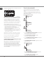
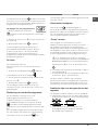
The control panel described in this manual is only a
representative example: it may not exactly match the panelon
your appliance.
1 INCREASE TIME button increases the time value
set on the timer (see Start-up and use).
2 DECREASE TIME button decreases the time value
set on the timer (see Start-up and use).
3 COOKING ZONE SELECTOR button shows a
particular cooking zone has been selected and
therefore various adjustments are possible.
4 COOKING ZONE SELECTOR button is used to
select the desired cooking zone.
5 POWER indicator provides a visual display for the
current heat level.
6 ON/OFF button switches the appliance on and off.
7 ON/OFF indicator light shows whether the appliance
is on or off.
8 PROGRAMME TIMER button controls the cooking
programme times (see Start-up and use).
9 PROGRAMME TIMER display shows which
programme has been selected (see Start-up and use).
10 COOKING ZONE PROGRAMMED indicator lights
show which cooking zones are being used during a
cooking programme (see Start-up and use).
11 CONTROL PANEL LOCK button prevents
accidental changes to the hob settings (see Start-up
and use).
12 CONTROL PANEL LOCK indicator light
shows the control panel has been locked (see Start-
up and use).
13 COOKING ZONE POWER SELECTOR
buttons switch on the hotplate and control the power
(see Start-up and use).
14 TIMER indicator light shows that the timer has been
activated
! This product complies with the requirements of the
latest European Directive on the limitation of power
consumption of the standby mode.
If no operations are carried out for a period of 2
minutes, after the residual heat indicator lights turn
off and the fan stops (if present), the appliance
automatically switches to the .off mode..
The appliance resumes the operating mode once the
ON/OFF button is pressed.
Le tableau de bord qui est
décrit n.a qu.une valeur d.exemple :
il peut ne pas correspondre au modèle acheté.
1 Touche AUGMENTATION DU TEMPS pour augmenter le
temps du programmateur (voir Mise en marche et utilisation).
2 Touche DIMINUTION DU TEMPS pour diminuer le temps
du programmateur (voir Mise en marche et utilisation).
3 Voyant FOYER SELECTIONNÉ pour signaler que le foyer
correspondant a été sélectionné et que les régulations
sont donc possibles.
4 Touche SÉLECTION FOYER pour sélectionner le foyer
souhaité
5 Indicateur de PUISSANCE : une colonne lumineuse pour
signaler le niveau de puissance atteint.
6 Touche ON/OFF pour allumer ou éteindre l’appareil.
7 Voyant ON/OFF : il signale si l’appareil est allumé ou
éteint.
8 Touche PROGRAMMATEUR pour programmer la durée
d’une cuisson (voir Mise en marche et Utilisation).
9 Afficheur PROGRAMMATEUR: pour afficher les choix
correspondant à la programmation (voir Mise en marche et
utilisation).
10 Voyants FOYER PROGRAMMÉ: ils indiquent les foyers
quand une programmation est lancée (voir Mise en marche
et utilisation).
11 Touche VERROUILLAGE DES COMMANDES pour
empêcher toute intervention extérieure sur les réglages de
la table de cuisson (voir Mise en marche et Utilisation).
12 Voyant COMMANDES VERROUILLÉES : pour signaler
le verrouillage des commandes (voir Mise en marche et
Utilisation).
13 Touche SÉLECTION PUISSANCE FOYERS pour allumer
le foyer et régler sa puissance (voir Mise en marche et
utilisation).
14 Voyant MINUTEUR il signale que le minuteur est activé
! Ce produit est conforme à la nouvelle Directive Européenne sur la
réduction de la consommation d’énergie en mode standby. Sans
opérations pendant 2 minutes, après
l’extinction des voyants de chaleur résiduelle et l’arrêt du ventilateur
(si existants), l’appareil se place automatiquement en “off mode”. Pour
remettre l’appareil en mode de fonctionnement
normal, appuyer sur la touche ON/OFF.
* Only available in certain models. * N’existe que sur certains modèles
13
1
2
3 5
4
6
7
8
910
11
12
14

4
Descripción del aparato
Panel de control
ES
Descrição do aparelho
Painel de comandos
PT
El panel de control se describe a continuación a modo de
ejemplo: puede no ser una exacta reproducción del
modelo adquirido.
1 Botón AUMENTO TIEMPO para aumentar el tiempo
del temporizador (ver Puesta en funcionamiento y
modo de empleo).
2 Botón DISMINUCIÓN TIEMPO para disminuir
el tiempo del temporizador (ver Puesta en
funcionamiento y modo de empleo).
3 Piloto ZONA DE COCCIÓN SELECCIONADA indica
que ha sido seleccionada dicha zona de cocción
y, por lo tanto, se pueden realizar las distintas
regulaciones
4 Botón SELECCIÓN DE ZONA DE COCCIÓN para
seleccionar la zona de cocción deseada
5 Indicador de POTENCIA: indica visualmente el nivel
de calor alcanzado.
6 Botón ON/OFF para encender y apagar el aparato.
7 Piloto ON/OFF: indica si el aparato está encendido o
apagado.
8 Botón TEMPORIZADOR DE PROGRAMACIÓN
para programar la duración de una cocción (ver
Puesta en funcionamiento y uso).
9 Display TEMPORIZADOR DE PROGRAMACIÓN:
visualiza las selecciones correspondientes a la
programación (ver Puesta en funcionamiento y uso).
10 Pilotos ZONA DE COCCIÓN PROGRAMADA:
indican las zonas de cocción cuando comienza una
programación (ver Puesta en funcionamiento y uso).
11 Botón BLOQUEO DE MANDOS para impedir
modificaciones fortuitas a las regulaciones de la
encimera (ver Puesta en funcionamiento y uso).
12 Piloto MANDOS BLOQUEADOS: indica que se ha
producido el bloqueo de los mandos (ver Puesta en
funcionamiento y uso).
13 Botón SELECCIÓN POTENCIA ZONAS COCCIÓN
para encender la placa y regular la potencia (ver
Puesta en funcionamiento y modo de empleo).
14 Piloto CONTADOR DE MINUTOS indica que se ha
activado el contador de minutos
! Este producto satisface los requisitos establecidos
por la nueva Directiva europea sobre la limitación de
los consumos energéticos en standby.
Si no se realizan operaciones por 2 minutos, una vez
que se apagan los luces piloto del calor residual y
del ventilador (si están presentes), el aparato se
coloca de forma automática en el modo .off mode..
El aparato vuelve al modo operativo utilizando la
tecla ON/OFF.
O painel de comandos descrito a seguir está representado para
fins explicativos: pode não ser uma exacta
reprodução do modelo comprado.
1 Botão AUMENTAR TEMPO para aumentar o tempo
do timer (veja Início e utilização).
2 Botão DIMINUIR TEMPO para diminuir o tempo do
timer (veja Início e utilização).
3 Indicador luminoso ZONA DE COZEDURA
SELECCIONADA indica que a zona de cozedura
relativa foi seleccionada e são portanto possíveis as
várias regulações.
4 Botão SELECÇÃO ZONA DE COZEDURA para
seleccionar a zona de cozedura desejada.
5 Indicador POTÊNCIA sinaliza visualmente o nível de
calor alcançado.
6 Botão ON/OFF para ligar e desligar o aparelho.
7 Indicador ON/OFF: sinaliza se o aparelho está
aceso ou apagado.
8 Botão TIMER DE PROGRAMAÇÃO para regular a
programação da duração de uma cozedura (veja
Início e utilização).
9 Display TIMER DE PROGRAMAÇÃO: visualiza
as escolhas relativas à programação (veja Início e
utilização).
10 Indicadores luminosos ZONA DE COZEDURA
PROGRAMADA: indicam as zonas de cozedura
quando se inicia uma programação (veja Início e
utilização).
11 Botão BLOQUEIO DOS COMANDOS para impedir
modificações acidentais das regulações do plano
de cozedura (veja Início e utilização).
12 Indicador luminoso COMANDOS BLOQUEADOS:
sinaliza o bloqueio dos comandos (veja Início e
utilização).
13 Botão SELECCIONAR POTÊNCIA DAS ZONAS DE
COZEDURA para ligar a chapa e regular a potência
(veja Início e utilização).
14 Indicador luminoso CONTADOR DE MUNITOS
indica que está activo o contador de minutos.
! Este produto satisfaz os requisitos impostos pela
nova Directiva Europeia sobre a limitação dos
consumos energéticos em stand-by.
Se não se efectuarem operações por 2 minutos,
depois que os indicadores de calor resíduo e da
ventoinha (se presentes) se desligarem, o aparelho
coloca-se automaticamente na modalidade .off
mode..
O aparelho voltará para a modalidade operativa ao
carregar na tecla ON/OFF.
* Presente sólo en algunos modelos. * Há somente em alguns modelos.

GB
5
IT
DE
Beschreibung des Gerätes
Bedienfeld
Das hier beschriebene Bedienfeld dient nur als Beispiel, es
handelt sich nicht unbedingt um eine genaue
Widergabe des von Ihnen erworbenen Modells.
1 Taste ZEIT ERHÖHEN zur Verlängerung der Zeit des
Timers (siehe Inbetriebsetzung und Gebrauch).
2 Taste ZEIT HERABSETZEN zur Verkürzung der Zeit
des Timers (siehe Inbetriebsetzung und Gebrauch).
3 Kontrollleuchte GEWÄHLTE KOCHZONE:
Diese zeigt an, dass die der Kontrollleuchte
entsprechende Kochzone gewählt wurde und die
gewünschten Einstellungen demnach vorgenommen
werden können.
4 Taste WAHL DER KOCHZONE: Mittels dieser wird
die gewünschte Kochzone gewählt.
5 LEISTUNGSANZEIGE: Auf dieser ist der jeweils
erreichte Heizwert ersichtlich.
6 Taste ON/OFF: Zum Ein- bzw. Ausschalten des
Gerätes.
7 Kontrollleuchte ON/OFF: Diese zeigt an, ob das
Gerät ein- oder ausgeschaltet ist.
8 Taste PROGRAMMIERUNGSTIMER: Mittels
dieser Taste kann die für jede Kochzone jeweils
programmierte Zeit reguliert werden (siehe
Inbetriebsetzung und Gebrauch).
9 Display PROGRAMMIERUNGSTIMER: Auf diesem
Display werden die jeweils programmierten Zeiten
angezeigt (siehe Inbetriebsetzung und Gebrauch).
10 Kontrollleuchten PROGRAMMIERTE KOCHZONE:
Diese zeigen die Kochzonen an, die programmiert
wurden (siehe Inbetriebsetzung und Gebrauch).
11 Taste SPERRE DER SCHALTELEMENTE: Um
versehentliche Änderungen der am Kochfeld
erfolgten Einstellungen zu verhindern (siehe
Inbetriebsetzung und Gebrauch).
12 Kontrollleuchte SCHALTELEMENTE GESPERRT:
Diese signalisiert, dass die Schaltelemente gesperrt
wurden (siehe Inbetriebsetzung und Gebrauch).
13 Taste LEISTUNGSREGLER KOCHZONE zum
Einschalten sowie zur Leistungsregelung der
Kochzone (siehe Inbetriebsetzung und Gebrauch).
14 Kontrollleuchte KURZZEITWECKER: Diese
signalisiert, dass der Kurzzeitwecker läuft.
! Dieses Produkt entspricht den Vorschriften der
neuen Europäischen Richtlinie zur Einschränkung
des Energieverbrauchs im Standby.
Werden für 2 Minuten keine Tasten gedrückt, dann
stellt sich das Gerät nach Ausschalten der Anzeigen
für Resthitze und des Lüfters (wenn vorhanden)
automatisch in den “off mode”.
Das Gerät kehrt durch Drücken der Taste ON/OFF in
den Betriebsmodus zurück.
Il pannello di controllo che qui viene descritto è
rappresentato a fini esemplificativi: può non essere una
esatta riproduzione del modello acquistato.
1 Tasto AUMENTO TEMPO per aumentare il tempo
del timer (vedi Avvio e utilizzo).
2 Tasto DIMINUZIONE TEMPO per diminuire il tempo
del timer (vedi Avvio e utilizzo).
3 Spia ZONA DI COTTURA SELEZIONATA indica
che la zona di cottura relativa è stata selezionata e
quindi sono possibili le varie regolazioni
4 Tasto SELEZIONE ZONA DI COTTURA per
selezionare la zona di cottura desiderata
5 Indicatore POTENZA: segnala visivamente il livello
di calore raggiunto.
6 Tasto ON/OFF per accendere e spegnere
l’apparecchio.
7 Spia ON/OFF: segnala se l’apparecchio è acceso
o spento.
8 Tasto TIMER DI PROGRAMMAZIONE per regolare
la programmazione della durata di una cottura (vedi
Avvio e utilizzo).
9 Display TIMER DI PROGRAMMAZIONE: visualizza
le scelte relative alla programmazione (vedi Avvio e
utilizzo).
10 Spie ZONA DI COTTURA PROGRAMMATA:
indicano le zone di cottura quando si avvia una
programmazione (vedi Avvio e utilizzo).
11 Tasto BLOCCO DEI COMANDI per impedire
modifiche fortuite alle regolazioni del piano cottura
(vedi Avvio e utilizzo).
12 Spia COMANDI BLOCCATI: segnala l’avvenuto
blocco dei comandi (vedi Avvio e utilizzo).
13 Tasti SELEZIONE POTENZA ZONE COTTURA per
accendere la piastra e regolare la potenza (vedi
Avvio e utilizzo).
14 Spia CONTAMINUTI indica che è attivo il
contaminuti
! Questo prodotto soddisfa i requisiti imposti dalla
nuova Direttiva Europea sulla limitazione dei consumi
energetici in standby.
Se non si eseguono operazioni per 2 minuti, dopo
lo spegnimento delle spie di calore residuo e della
ventola (ove presenti), l’apparecchio si dispone
automaticamente in modalità “off mode”.
L’apparecchio ritorna in modalità operativa agendo sul
tasto ON/OFF.
Descrizione dell’apparecchio
Pannello di controllo
* Nur bei einigen Modellen.
* Presente solo in alcuni modelli.

6
NL PL
Beschrijving van het apparaat
Bedieningspaneel
Opis urządzenia
Panel sterowania
Het bedieningspaneel dat hier wordt beschreven en
afgebeeld geldt alleen als voorbeeld: het is mogelijk dat
het niet exact overeenkomt met het door u aangeschafte
model.
1 Toets TOENAME TIJD om de tijd van de timer toe te
laten nemen (zie Starten en gebruik).
2 Toets AFNAME TIJD om de tijd van de timer af te
laten nemen (zie Starten en gebruik).
3 Controlelampje GESELECTEERD KOOKGEDEELTE
geeft aan dat het betreffende kookgedeelte
geselecteerd is en dat u het kunt regelen.
4 Toets SELECTEREN KOOKGEDEELTE om het
gewenste kookgedeelte te selecteren
5 AanwijzerVERMOGEN: geeft het bereikte
warmteniveau aan.
6 Toets ON/OFF voor het in- en uitschakelen van het
apparaat.
7 Controlelampje ON/OFF: geeft aan of het apparaat in-
of uitgeschakeld is.
8 Toets PROGRAMMERINGSTIMER om de
programmering van de kookduur te regelen (zie
Starten en gebruik).
9 Display PROGRAMMERINGSTIMER: toont de
keuzes betreffende de programmering aan (zie
Starten en gebruik).
10 Controlelampjes GEPROGRAMMEERD
KOOKGEDEELTE: tonen de kookgedeeltes aan als u
een programmering start (zie Starten en gebruik).
11 Toets BLOKKERING BEDIENINGSPANEEL om
te voorkomen dat er ongewilde wijzigingen aan de
regeling van het kookvlak worden uitgevoerd (zie
Starten en gebruik).
12 Controlelampje BLOKKERING
BEDIENINGSPANEEL: toont dat de blokkering van
het bedieningspaneel heeft plaatsgevonden (zie
Starten en gebruik).
13 Toets SELECTEREN KOOKZONES om de kookplaat
aan te zetten en het vermogen te regelen (zie Starten
en gebruik).
14 Controlelampje TIMER geeft aan dat de timer actief
is.
! Dit product voldoet aan de eisen die gesteld worden door
de nieuwe Europese Richtlijn voor energiebesparing voor
apparaten in de standby-stand.
Wanneer 2 minuten lang geen handelingen worden
uitgevoerd gaat het apparaat, na het uitgaan van de
waarschuwingslampjes voor restwarmte en voor de
ventilator (indien aanwezig), automatisch in de “off mode”.
Door op de ON/OFF toets te drukken, keert het apparaat
weer terug in de operationele stand.
Opisany tu panel sterowania jest przedstawiony jako
przykład: nie musi być dokładnie taki sam, jak panel
zainstalowany w zakupionym urządzeniu.
1 Przycisk POWIEKSZA CZAS aby powiększyć czas
timera (patrz Uruchomienie i użytkowanie).
2 Przycisk SKRÓCA CZAS aby skrócić czas timera
(patrz Uruchomienie i użytkowanie).
3 Kontrolka WYBRANEGO POLA GRZEJNEGO
wskazuje, ze dane pole grzejne zostalo wybrane, a
wiec mozliwe sa rózne regulacje
4 Przycisk WYBORU POLA GRZEJNEGO do wybrania
zadanego pola grzejnego.
5 Wskaźnik MOCY: wizualnie sygnalizuje osiągnięty
poziom ciepła.
6 Przycisk ON/OFF do wlaczania i wylaczania
urzadzenia.
7 Kontrolka ON/OFF: sygnalizuje, czy urzadzenie jest
wlaczone, czy wylaczone.
8 Przycisk REGULATORA CZASOWEGO
PROGRAMOWANIA do regulacji programowania
czasu trwania gotowania (patrz Uruchomienie i
uzytkowanie).
9 Wyswietlacz REGULATORA CZASOWEGO
PROGRAMOWANIA: wyswietla dane dotyczace
programowania (patrz Uruchomienie i uzytkowanie).
10 Kontrolki ZAPROGRAMOWANEGO POLA
GRZEJNEGO: wskazuja pola grzejne przy
rozpoczynaniu programowania (patrz Uruchomienie i
uzytkowanie).
11 Przycisk BLOKADY STEROWANIA do zapobiegania
przypadkowym zmianom parametrów przy regulacji
plyty grzejnej (patrz Uruchomienie i uzytkowanie).
12 Kontrolka BLOKADY STEROWANIA : sygnalizuje
zablokowanie sterowania (patrz Uruchomienie i
uzytkowanie).
13 Przycisk ZWIĘKSZENIA MOCY PŁYTY do włączania
płyty i do regulacji mocy (patrz Uruchomienie i
użytkowanie).
14 Kontrolka MINUTNIKA wskazuje, ze minutnik jest
wlaczony
! Ten produkt spe
łnia wymogi dyrektywy wspólnotowej
dotyczącej ograniczenia zużycia energii w trybie
czuwania.
Jeśli przez 2 minuty nie są wykonywane żadne
operacje, po wyłączeniu wskaźnika ciepła resztkowego
i wentylatora (jeśli obecne), urządzenie automatycznie
przechodzi w tryb „off mode”.
Urządzenie powraca do trybu aktywnego po naciśnięciu
przycisku ON/OFF.
* Slechts op enkele modellen aanwezig.
* Znajduje siê tylko w niektórych modelach.

7
GB
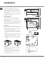
Installation
! Before operating your new appliance please read
this instruction booklet carefully. It contains important
information concerning the safe operation, installation
and maintenance of the appliance.
! Please keep these operating instructions for future
reference. Pass them on to any new owners of the
appliance.
Positioning
! Keep all packaging material out of the reach of
children. It may present a choking or suffocation
hazard (see Precautions and tips).
! The appliance must be installed by a qualified
professional in accordance with the instructions
provided. Incorrect installation may cause harm to
people and animals or may damage property.
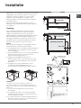
Built-in appliance
Use a suitable cabinet to ensure that the appliance
functions properly.
• The supporting surface must be heat-resistant up to
a temperature of approximately 100°C.
• If the appliance is to be installed above an oven,
the oven must be equipped with a forced ventilation
cooling system.
• Avoid installing the hob above a dishwasher: if this
cannot be avoided, place a waterproof separation
device between the two appliances.
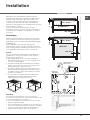
• Depending on the hob you want to install, the
cabinet must have the following dimensions (see
gure):
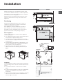
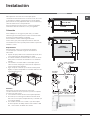
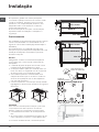
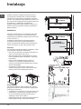
Ventilation
To allow adequate ventilation and to avoid overheating of
the surrounding surfaces the hob should be positioned as
follows:
• At a minimum distance of 40 mm from the back
panel.
• So that a minimum distance of 20 mm is maintained
between the installation cavity and the cabinet
underneath.
• Kitchen cabinets adjacent to the appliance and taller
than the top of the hob must be at least 600 mm
from the edge of the hob.
FRONT SIDE
OF HOB
SUPPORTING
SURFACE
30
40
UNDERSIDE
OF HOB
5 mm
min. 20 mm
min. 20 mm
min. 40 mm
COMPARTMENT
5 mm
min. 40 mm
FAN-ASSISTED
OVEN
560 +/- 1
490 +/- 1
48
590
520
690
520
560 +/- 1
490 +/- 1
48

8
GB
Fixing
The appliance must be installed on a perfectly level
supporting surface.
Any deformities caused by improper fixing could affect
the features and operation of the hob.
The thickness of the supporting surface
should be taken
into account when choosing
the length of the screws for
the fixing hooks:
• 30 mm thick: 17.5 mm screws
• 40 mm thick: 7.5 mm screws
Fix the hob as follows:
1. Use short flat-bottomed screws to fix the 4 alignment
springs in the holes provided at the central point of
each side of the hob.
2. Place the hob in the cavity, make sure it is in a
central position and push down on the whole perimeter
until the hob is stuck to the supporting surface.
3. For hobs with raised sides: After inserting the hob
into its cavity, insert the 4 fixing hooks (each has its
own pin) into the lower edges of the hob, using the
long pointed screws to fix them in place, until the glass
is stuck to the supporting surface.
! The screws for the alignment springs must remain
accessible.
! In order to adhere to safety standards, the appliance
must not come into contact with electrical parts once it
has been installed.
! All parts which ensure the safe operation of the
appliance must not be removable without the aid of a
tool.
Electrical connection
! The electrical connection for the hob and for any built-
in oven must be carried out separately, both for safety
purposes and to make extracting the oven easier.
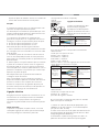
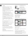
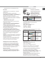
Terminal board
On the lower part of the appliance there is a
connection box for the different types of electricity
supply (the picture is only
an indication and is not an
exact representation of the
purchased model).
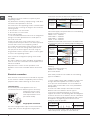
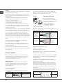
Single-phase connection
The hob is equipped with a pre-connected electricity
supply cable, which is designed for single-phase
connection. Connect the wires in accordance with the
instructions given in the following table and diagrams:
Voltage and
mains frequency
Electrical cable Wire connection
230-240V 1+N ~
220-240V 1+N ~
50/60 Hz
: yellow/green
N
: the two blue wires together
L
: brown and black together
Other types of connection
If the mains supply corresponds with one of the following:
Voltage and mains frequency
• 400V - 2+N ~ 50/60 Hz
• 220-240V 3 ~ 50/60 Hz
• 230-240V 3 ~ 50/60 Hz
• 400V - 2+2N ~ 50/60 Hz
Separate the wires and connect them in accordance with
the instructions given in the following table and diagrams:
Voltage and
mains frequency
Electrical cable Wire connection
400V - 2+N ~
50/60 Hz
230-240V 3 ~
220-240V 3 ~
50/60 Hz
: yellow/green;
N: the two blue wires
together
L1: black
L2: brown
400V - 2+2N ~
50/60 Hz
: yellow/green;
N1: blue
N2: blue
L1: black
L2: brown
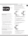
If the mains supply corresponds with one of the
following:
Voltage and mains frequency
• 400V 3 - N ~ 50/60 Hz
proceed as follows:
! The cable provided is not suitable for the following
types of installation.
1. Use a suitable supply cable, H05RR-F or higher, with
the right dimensions (cable cross section: 25 mm).
2. To open the terminal board, use a screwdriver as
a lever under the side tabs of the cover (see Terminal
board picture).
3. Loosen the cable clamp screw and the terminal
board screws in accordance with the type of
connection required and position the connection
supports as shown in the following table and diagrams.
4. Position the wires in accordance with the information
given in the following table and diagrams and connect
the appliance by tightening all the screws for the
springs as much as possible.
Voltage and
mains frequency
Electrical connections Terminal board
400V 3-N ~
50/60 Hz
Three-phase 400
5. Secure the power supply cable by fastening the
cable clamp screw, then put the cover back on.
UNDERSIDE OF HOB

9
GB
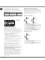
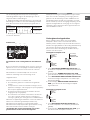
Three-phase 400
Connecting the electricity supply cable to the mains
If the appliance is being connected directly to the
electricity mains an omnipolar switch must be installed
with a minimum opening of 3 mm between contacts.
! The installer must ensure that the correct electrical
connection has been made and that it is fully compliant
with safety regulations.
Before connecting the appliance to the power supply,
make sure that:
• The appliance is earthed and the plug is compliant
with the law.
• The socket can withstand the maximum power of
the appliance, which is indicated on the data plate
located on the appliance itself.
• The voltage falls within the range of values indicated
on the data plate.
• The socket is compatible with the plug of the
appliance. If the socket is incompatible with the
plug, ask an authorised technician to replace it. Do
not use extension cords or multiple sockets.
! Once the appliance has been installed, the power
supply cable and the electrical socket must be easily
accessible.
! The cable must not be bent or compressed.
! The cable must be checked regularly and replaced
by authorised technicians only.
! The manufacturer declines any liability should
these safety measures not be observed.
! Do not remove or replace the power supply cable
for any reason. Its removal or replacement will void
the warranty and the CE marking. INDESIT does not
assume liability for accidents or damage arising from
replacement/removal of the original power supply
cable. Replacement can only be accepted when
carried out by personnel authorised by INDESIT and
using an original spare part.
U-bolt
connection support
Neutral
Earth
Phase Phase Phase
1
2
3
5
4
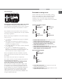
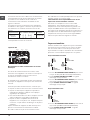
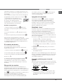
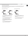
Extendable cooking zones
Certain models are fitted with extendable cooking
zones. These may be circular or oval and may vary
in their extensibility (they may be double or triple
hotplates). A list of controls is given below (these
controls are only present in models with the extendable
cooking zone option).
Circular extendable hotplate
• DOUBLE HOTPLATE ON button switches on the
double hotplate (see Start-up and use).
• DOUBLE HOTPLATE ON indicator light shows
the double hotplate has been switched on.
• TRIPLE HOTPLATE ON button switches on the
triple hotplate (see Start-up and use).
• TRIPLE HOTPLATE ON indicator light shows the
triple hotplate has been switched on.
Oval extendable hotplate
• OVAL HOTPLATE ON button switches on the oval
hotplate (see Start-up and use).
• OVAL HOTPLATE ON indicator light shows the oval
hotplate has been switched on.
TRIPLE
HOTPLATE ON
indicator light
TRIPLE
HOTPLATE ON
button
DOUBLE
HOTPLATE ON
indicator light
DOUBLE
HOTPLATE ON
button
OVAL
HOTPLATE ON
indicator light
OVAL
PLATE ON
button

10
GB
Start-up and use
! The glue applied on the gaskets leaves traces of
grease on the glass. Before using the appliance, we
recommend you remove these with a special non-
abrasive cleaning product. During the first few hours
of use there may be a smell of rubber which will
disappear very quickly.
! A few seconds after the hob is connected to the
electricity supply, a buzzer will sound. The hob may
now be switched on.
! If the - or + button is pressed for an extended
period of time, the display scrolls quickly though the
power levels and timer minutes.
Switching on the hob
To switch the hob on, press and hold the button
for approximately one second.
Switching on the cooking zones
Each cooking zone is controlled using a selector
button
and a power adjustment device consisting
of power level selector buttons between the values of 0
and 9.
• To begin operating a cooking zone, press the
corresponding control button and set the desired
power level using the power level selector buttons
between 0 and 9.
Switching off the cooking zones
To switch off a cooking zone, select it using the
corresponding selector button
and:
• Press power level selector button 0: this immediately
returns the power setting to 0 and the cooking zone
switches off.
Power function
The power function for the cooking zones may be used
to shorten heating-up times. Activate and set the power
level for the desired cooking zone
as described in
the previous paragraph. Press and hold the selector
button corresponding to the desired cooking zone
for at least 2 seconds. The display, the power level
indicator, will alternately show the letter “P” and the
power level set previously until the desired power level
has been reached. Once this level has been reached,
the display will revert to showing the set power level.
To deactivate this function, press and hold – for at
least 2 seconds - the selector button corresponding
to the cooking zone on which the
function has
been activated; alternatively, select a different power
level between 0 and 9 using the power level selector
buttons.
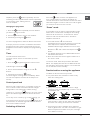
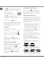
Heating elements
Two types of heating element may be installed,
depending on the appliance model: halogen and
radiant elements.
Halogen elements emit heat via radiation from the
halogen lamps they contain.
They have similar properties to gas burners: they are
easy to control and reach set temperatures quickly,
allowing you to see the power level instantly.
Radiant elements consist of a series of coils which
allow heat to be distributed evenly at the base of
the cookware, so that all slow-flame cooking may be
performed successfully, for example stews, sauces or
reheated dishes.
Programming the cooking duration
! All the cooking zones may be programmed
simultaneously, for a duration between 1 and 99
minutes.
1. Select the cooking zone using the corresponding
selector button.
2. Adjust the power level of the cooking zone.
3. Press the
programming button. The indicator
light corresponding to the selected zone will start
flashing.
4. Set the cooking duration using the
- and +
buttons.
5. Confirm by pressing the
button or automatic
selection occurs after 10 seconds.
The timer begins counting down immediately. A buzzer
sounds for approximately 1 minute and the cooking
zone switches off when the set programme has
finished. Repeat the above procedure for each hotplate
you wish to programme.
Using multiple programmes and the display
If one or more hotplates are programmed, the display
will show the data for the hotplate with the least time
remaining, and the light corresponding to the position
of the hotplate will flash. The lights corresponding to
the other hotplates programmed will be switched on.
To visualise the time remaining for the other programmed

11
GB
hotplates, press the button repeatedly: the time
remaining for each hotplate will be shown sequentially
in a clockwise order, starting from the
front left hotplate.
Changing the programme
1. Press the
button repeatedly until the duration
you wish to change is shown.
2. Use the
buttons to set the new duration.
3. Confirm by pressing the
button.
To cancel a programme, follow the above instructions.
At step 2, press the
- button: the duration decreases
progressively until it reaches 0 and switches off. The
programme resets and the display exits programming
mode.
Timer
The hob must be switched on.
The timer can be used to set a duration up to 99
minutes.
1. Press the
programming button until the timer
indicator light is illuminated
.
2. Set the desired duration using the
- and +
buttons.
3. Confirm by pressing the
button.
The timer begins counting down immediately. When
the time has elapsed, a buzzer will sound (for one
minute).
Control panel lock
When the hob is switched on, it is possible to lock the
oven controls in order to avoid accidental changes
being made to the settings (by children, during
cleaning, etc.). Press the
button to lock the control
panel: the indicator light above the button will switch
on.
To use any of the controls (e.g. to stop cooking), you
must switch off this function. Press the
button for a
few moments, the indicator light will switch off and the
lock function will be removed.
Switching off the hob
Press the button to switch the appliance off.
If the control panel lock has been activated, the
controls will continue to be locked even after the hob is
switched on again. In order to switch the hob on again,
you must first remove the lock function.
“Demo” mode
It is possible to set the hob to a demonstration mode
where all the controls work normally but the heating
elements do not switch on. To activate the “demo”
mode the hob must be switched on, with all the
hotplates switched off.
• Press and hold the
+ and - buttons
simultaneously for 6 seconds. When the 6 seconds
have elapsed, the ON/OFF and CONTROLS
LOCKED indicator lights will flash for one second.
Release the
+ and - buttons and press the
button;
• The display will show the text DE and MO and the
hob will be switched off.
• When the hob is switched on again it will be set to
the “demo” mode.
To exit this mode, follow the procedure described
above. The display will show the text DE and OF and
the hob will be switched off. When it is next switched
on, the hob will function normally.
Practical advice on using the appliance
To obtain the best results from your hob:
• Use pans with a thick, flat base in order to fully
utilise the cooking zone.
• Always use pans with a diameter which is large
enough to cover the hotplate fully, in order to use all
the available heat.
• Make sure that the base of the cookware is always
clean and dry, in order to fully utilise and extend the
life of both the cooking zones and the cookware.
• Avoid using the same cookware which has been
used on gas burners: the heat concentration on gas
burners may distort the base of the pan, causing it
not to adhere correctly.

12
GB
Safety devices
Residual heat indicators
Each cooking zone is equipped with a residual heat
indicator. This indicator signals which cooking zones
are still at a high temperature. If the power display
shows
, the cooking zone is still hot. It is possible,
for example, to keep a dish warm or melt butter or
chocolate. As the cooking zone cools, the power
display will show
. The display switches off when the
cooking zone has cooled sufficiently.
Overheating protection
If the electronic elements overheat, the hob switches
off automatically and
F appears on the display,
followed by a flashing number. When the temperature
has reached a suitable level, this message disappears
and the hob may be used again.
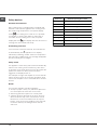
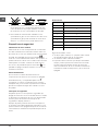
Safety switch
The appliance has a safety switch which automatically
switches the cooking zones off after they have been
in operation for a certain amount of time at a particular
power level. When the safety switch has been
triggered, the display shows “0”.
For example: the right rear hotplate is set to 5 and will
switch off after 5 hours of continuous operation, while
the front left hotplate is set to 2 and will switch off after
8 hours.
Buzzer
This can also indicate several irregularities:
• An object (a pan, cutlery, etc.) has been placed on
the control panel for more than 10 seconds.
• Something has been spilt on the control panel.
• A button has been pressed for too long. All of the
above situations may cause the buzzer to sound.
Remove the cause of the malfunction to stop the
buzzer. If the cause of the problem is not removed,
the buzzer will keep sounding and the hob will
switch off.
Power level
1
2
3
4
5
6
7
8
9
Maximum operating time in hours
9
8
7
6
5
4
3
2
1

13
GB
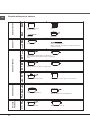
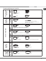
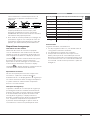
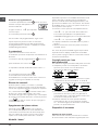
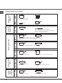
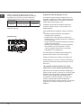
Practical cooking advice
ª
Pressure cooking
Pressure cooker
Frying
Grilling Boiling
Very high-flame
cooking
High-flame
cooking
Medium-flame cookingLow-flame
cooking
Very
low-flame
cooking
•
•
¶
Crêpes Cooking on a high flame and browning
(roasts, steaks, escalopes, fish fillets,
fried eggs)
¶
§
Fast thickening (liquid juices)
Boiling water (pasta, rice, vegetables)
Milk
§
S
Slow thickening (dense juices)
S
¢
Bain-marie cooking
Pressure cooking after whistle
¢
£
™
Low-flame cooking (stews)
Reheating dishes
™
¡
Chocolate sauce Keeping food hot

14
GB
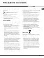
Precautions and tips
! This appliance has been designed and manufactured
in compliance with international safety standards. The
following warnings are provided for safety reasons and
must be read carefully.
This appliance conforms to the following
European Economic Community directives:
- 2006/95/EEC dated 12/12/06 (Low Voltage) and
subsequent amendments;
- 2004/108/EEC dated 15/12/04 (Electromagnetic
Compatibility) and subsequent amendments;
- 93/68/EEC dated 22/07/93 and subsequent
amendments.
- 1275/2008 stand-by/off mode.
General safety
! Make sure that the air inlet behind the fan grille is
never obstructed. The built-in hob should, in fact, be
provided with suitable ventilation for the cooling of the
electronic components used in the appliance.
• The appliance was designed for domestic use inside
the home and is not intended for commercial or
industrial use.
• The appliance must not be installed outdoors, even
in covered areas. It is extremely dangerous to leave
the appliance exposed to rain and storms.
• Do not touch the appliance when barefoot or with
wet or damp hands and feet.
• The appliance must be used by adults only for
the preparation of food, in accordance with the
instructions provided in this booklet. Do not use the
hob as a worktop or chopping board.
• The glass ceramic hob is resistant to mechanical
shocks, but it may crack (or even break) if hit with
a sharp object such as a tool. If this happens,
disconnect the appliance from the electricity mains
immediately and contact a Service Centre.
• Ensure that power supply cables of other electrical
appliances do not come into contact with the hot
parts of the hob.
• Remember that the cooking zones remain relatively
hot for at least thirty minutes after they have been
switched off. An indicator light provides a warning
when residual heat is present (see Start-up and use).
• Keep any object which could melt away from the
hob, for example plastic and aluminium objects, or
products with a high sugar content. Be especially
careful when using plastic film and aluminium foil or
packaging: if placed on surfaces which are still hot,
they may cause serious damage to the hob.
• Always make sure that pan handles are turned
towards the centre of the hob in order to avoid
accidental burns.
• When unplugging the appliance, always pull the
plug from the mains socket; do not pull on the cable.
• Never perform any cleaning or maintenance work
without having disconnected the appliance from the
electricity mains.
• The appliance should not be operated by people
(including children) with reduced physical, sensory
or mental capacities, by inexperienced individuals
or by anyone who is not familiar with the product.
These individuals should, at the very least, be
supervised by someone who assumes responsibility
for their safety or receive preliminary instructions
relating to the operation of the appliance.
• Do not look at the halogen lamps in the cooking
zones for long if they are present.
• Do not let children play with the appliance.
• Do not place metal objects (knives, spoons, pan
lids, etc.) on the hob as they may become hot..
• The appliance is not intended to be operated by
means of an external timer or separate remote-
control system.
Disposal
• When disposing of packaging material: observe
local legislation so that the packaging may be
reused.
• The European Directive 2002/96/EC relating
to Waste Electrical and Electronic Equipment
(WEEE) states that household appliances should
not be disposed of using the normal solid urban
waste cycle. Exhausted appliances should be
collected separately in order to optimise the cost
of re-using and recycling the materials inside the
machine, while preventing potential damage to the
atmosphere and to public health. The crossed-out
dustbin is marked on all products to remind the
owner of their obligations regarding separated
waste collection.
For further information relating to the correct
disposal of exhausted household appliances,
owners may contact the public service provided or
their local dealer.

15
GB
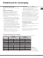
Care and maintenance
Switching the appliance off
Disconnect your appliance from the electricity supply before
carrying out any work on it.
Cleaning the appliance
! Do not use abrasive or corrosive detergents (for example,
products in spray cans for cleaning barbecues and ovens),
stain removers, anti-rust products, powder detergents or
sponges with abrasive surfaces: these may scratch the
surface beyond repair.
! Never use steam cleaners or pressure cleaners on the
appliance.
• It is usually sufficient simply to wash the hob using a damp
sponge and dry it with absorbent kitchen towel.
• If the hob is particularly dirty, rub it with a special glass
ceramic cleaning product, then rinse well and dry
thoroughly.
• To remove more stubborn dirt, use a suitable scraper.
Remove spills as soon as possible, without waiting for
the appliance to cool, to avoid residues forming crusty
deposits. You can achieve excellent results by using a
rust-proof steel wire sponge - specifically designed for
glass ceramic surfaces - soaked in soapy water.
• If any plastic or sugary substances are accidentally
melted on the hob, remove them immediately with the
scraper, while the surface is still hot.
• Once it is clean, the hob may be treated with a special
protective maintenance product: the invisible film left
by this product protects the surface from drips during
cooking. This maintenance task should be carried out
while the appliance is warm (not hot) or cold.
• Always remember to rinse the appliance well with clean
water and dry it thoroughly: residues can become
encrusted during subsequent cooking processes.
Stainless steel frame (only in models with outer frame)
Stainless steel can be marked by hard water which has been
left on the surface for a long time, or by cleaning products
containing phosphorus.
After cleaning, it is advisable to rinse the surface well and dry
it thoroughly. If water is spilt on the surface, dry it quickly and
thoroughly.
! Some hobs have an aluminium frame which is similar to
stainless steel. Do not use any cleaning or degreasing
products which are not suitable for use with aluminium.
Disassembling the hob
If it is necessary to disassemble the hob:
1. Loosen the screws fixing the alignment springs on each
side.
2. Loosen the screws holding the fixing hooks in each corner.
3. Take the hob out of its installation cavity.
! Do not attempt to repair the appliance yourself. If the
appliance breaks down, contact a Service Centre.
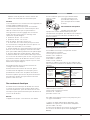
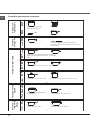
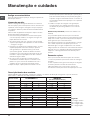
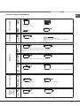
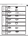
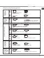
Technical description of the models
This table provides a model-by-model list of the energy absorption values, type of heating elements and diameters
of each cooking zone.
Key:
H = single hilight
HO = oval hilight
HD = double hilight
HT = triple hilight
Hobs
Cooking zone
Back Left
Back Right
Centre Left
Front Left
Front Right
Total power
Power (W)
HD 2200/1000
H 1200
H 1200
HO 2400/1500
Diameter (mm)
210/140
145
145
170x260
7000
KRO 742 DO Z
Power (W)
H 1400
HT 2700/1950/1050
HD 1700/700
Diameter (mm)
160
270/210/145
180/120
5900
KRO 632 TD X
KRO 632 TD Z
----------
Hobs
Cooking zone
Back Left
Back Right
Front Left
Front Right
Total power
Power (W)
HD 2200/1000
H 1400
H 1200
HD 1700/700
Diameter (mm)
210/140
160
145
180/120
6500
KRO 642 D B
KRO 642 D X
KRO 642 D Z; KRO 642 D C
Power (W)
HT 2300/1600/800
H 1200
H 1200
HO 2400/1500
Diameter (mm)
230/180/120
145
145
170x260
7100
KRO 642 TO B
KRO 642 TO X
KRO 642 TO Z
KRO 742 TO Z;KRO 642 TO B (PL)

16
FR
Installation
! Conserver ce mode d’emploi pour pouvoir le
consulter à tout moment. En cas de vente, de
cession ou de déménagement, veiller à ce qu’il
suive l’appareil pour informer le nouveau propriétaire
sur son fonctionnement et lui fournir les conseils
correspondants.
! Lire attentivement les instructions : elles contiennent
des conseils importants sur l’installation, l’utilisation et
la sécurité de cet appareil.
Positionnement
! Les emballages ne sont pas des jouets pour
enfants, il faut les mettre au rebut en respectant la
réglementation sur le tri sélectif des déchets (voir
Précautions et conseils).
! L’installation doit être effectuée par un professionnel
du secteur conformément aux instructions du fabricant.
Une mauvaise installation peut causer des dommages
à des personnes, des animaux ou des biens.
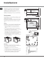
Encastrement
Pour garantir le bon fonctionnement de l’appareil, il
faut que le meuble possède des caractéristiques bien
précises :
• le matériau du plan d’appui doit pouvoir résister à
une température d’environ 100°C;
• en cas d’installation de la table de cuisson au-
dessus d’un four, il faut que ce dernier soit équipé
d’un dispositif de refroidissement par ventilation
forcée ;
• éviter d’installer la table de cuisson au-dessus d’un
lave-vaisselle : si c’est le cas, prévoir une séparation
étanche entre les deux appareils ;
• selon la table de cuisson à installer (voir gures),
la découpe du meuble doit avoir les dimensions
suivantes :
Aération
Pour permettre une bonne aération et pour éviter toute
surchauffe des surfaces autour de l’appareil, la table de
cuisson doit être positionnée :
• à au moins 40 mm de distance du mur arrière;
• de manière à ce qu’il reste au moins 20 mm de
distance entre la découpe d’encastrement et le
meuble en dessous.
• Les meubles jouxtant la table, dont la hauteur
560 +/- 1
490 +/- 1
48
590
520
690
520
560 +/- 1
490 +/- 1
48
5 mm
min. 20 mm
min. 20 mm
min. 40 mm
TIROIR
5 mm
min. 40 mm
CHALEUR
TOURNANTE
CÔTÉ AVANT DE LA
TABLE DE CUISSON
PLAN DE
TRAVAIL
30
40
TABLE DE CUISSON
RETOURNÉE

17
FR
dépasse celle du plan de cuisson, doivent être
placés à au moins 600 mm du bord du plan.
Fixation
Il est impératif d’assurer l’encastrement de l’appareil sur
un plan d’appui parfaitement plat.
Les déformations provoquées par une mauvaise
fixation risquent d’altérer les caractéristiques de la
table de cuisson ainsi que ses performances.
La longueur de la vis de réglage des crochets
de
fixation doit être réglée avant leur montage
selon
l’épaisseur du plan d’appui :
• épaisseur 30 mm : vis 17,5 mm;
• épaisseur 40 mm : vis 7,5 mm
Pour sa fixation, procéder comme suit :
1. Se servir des vis courtes sans pointe pour visser
les 4 ressorts de centrage dans les trous prévus sur
chaque côté de la table, en leur milieu;
2. insérer la table de cuisson dans la découpe prévue,
bien au centre et bien appuyer tout autour du cadre
pour que la table adhère parfaitement au plan d’appui.
3. pour les tables avec profils latéraux : après avoir
encastré la table de cuisson dans la découpe, insérer
les 4 crochets de fixation (chacun avec son goujon) sur
le périmètre inférieur de la table de cuisson et visser
avec les vis longues à pointe jusqu’à ce que le verre
adhère bien au plan d’appui.
! Il faut absolument que les vis des ressorts de
centrage soient accessibles.
! Conformément aux normes de sécurité, après
encastrement de l’appareil, il ne doit plus y avoir
possibilité de contact avec les parties électrifiées.
! Toutes les parties qui servent de protection doivent
être fixées de manière à ne pouvoir être enlevées
qu’avec l’aide d’un outil.
Raccordement électrique
! Le branchement électrique de la table de cuisson
et celui d’un éventuel four à encastrer doivent être
effectués séparément, pour des raisons de sécurité
électrique et pour pouvoir démonter plus facilement le
four en cas de besoin.
Bornier
L’appareil est équipé, sur le dessous, d’un boîtier
de raccordement à plusieurs types d’alimentation
électrique (la figure n’est
qu’indicative, elle peut ne
pas correspondre au modèle
acheté).
Raccordement monophasé
La table est fournie déjà
équipée d’un cordon d’alimentation prévu pour
raccordement monophasé. Procéder au raccordement
des fils en suivant les indications du tableau et des
dessins suivants :
Tension type et
fréquence réseau
Cordon électrique Raccordement fils
230-240V 1+N ~
220-240V 1+N ~
50/60 Hz
: jaune/vert;
N
: les 2 fils bleus ensemble
L
: le marron avec le noir
Autres types de branchement
Si l’installation électrique correspond à une des
caractéristiques suivantes :
Tension type et fréquence réseau
• 400V - 2+N ~ 50/60 Hz
• 220-240V 3 ~ 50/60 Hz
• 230-240V 3 ~ 50/60 Hz
• 400V - 2+2N ~ 50/60 Hz
Séparer les câbles et procéder au raccordement des
fils en suivant les indications du tableau et des dessins
suivants :
Tension type et
fréquence réseau
Cordon électrique Raccordement fils
400V - 2+N ~
50/60 Hz
230-240V 3 ~
220-240V 3 ~
50/60 Hz
: jaune/vert;
N: les 2 fils bleus
ensemble
L1: noir
L2: marron
400V - 2+2N ~
50/60 Hz
: jaune/vert;
N1: bleu
N2: bleu
L1: noir
L2: marron
Si l’installation électrique correspond à une des
caractéristiques suivantes :
Tension type et fréquence réseau
• 400V 3 - N ~ 50/60 Hz
procéder comme suit :
! Le câble éventuellement fourni n’est pas prévu pour
ces types d’installation.
1. Utiliser un câble d’alimentation approprié, type
H05RR-F ou supérieur, aux dimensions adéquates
(section câble : 25 mm).
2. Faire levier à l’aide d’un tournevis sur les languettes
du couvercle du bornier pour l’ouvrir (voir gure
Bornier).
TABLE DE CUISSON
RETOURNEE

18
FR
3. Dévisser la vis du serre-câble et les vis des bornes
correspondant au type de raccordement nécessaire
et positionner les cavaliers de raccordement
conformément aux indications du tableau et des
figures ci-dessous.
4. Positionner les fils conformément aux indications
du tableau et des figures ci-dessous et procéder au
raccordement en serrant à fond toutes les vis des
bornes.
Tension type et
fréquence réseau
Raccordements électriques Bornier
400V 3-N ~
50/60 Hz
Triphasé 400
5. Fixer le câble d’alimentation dans le serre-câble
correspondant et fermer le couvercle.
Triphasé 400
Branchement du câble d’alimentation au réseau
électrique
En cas de raccordement direct au réseau, il faut
intercaler entre l’appareil et le réseau un interrupteur
à coupure omnipolaire ayant au moins 3 mm
d’écartement entre les contacts.
! L’installateur est responsable du bon raccordement
électrique de l’appareil et du respect des normes de
sécurité.
Avant de procéder au branchement, s’assurer que :
• la prise est bien munie d’une terre conforme à la loi;
• la prise est bien apte à supporter la puissance
maximale de l’appareil, indiquée sur la plaque
signalétique de l’appareil ;
• la tension d’alimentation est bien comprise entre les
valeurs indiquées sur la plaque signalétique;
• la prise est bien compatible avec la fiche de
l’appareil. Si ce n’est pas le cas, remplacer la prise
ou la fiche, ne pas utiliser de rallonges ni de prises
multiples.
! Après installation de l’appareil, le câble électrique et la
prise de courant doivent être facilement accessibles
! Le câble ne doit être ni plié ni excessivement écrasé.
Cavalier
Neutre
Terre
Phase Phase Phase
1
2
3
5
4
! Le câble doit être contrôlé périodiquement et ne peut être
remplacé que par un technicien agréé.
! Nous déclinons toute responsabilité en cas de non
respect des normes énumérées ci-dessus.
! Ne retirer ou ne remplacer en aucun cas le câble
d’alimentation. Toute opération d’enlèvement ou de
remplacement annule automatiquement la garantie et la
marque CE INDESIT décline toute responsabilité en cas
d’accidents ou de dommages dérivants de l’enlèvement ou
du remplacement du câble d’alimentation original. Seul le
remplacement effectué par un technicien agréé INDESIT
utilisant une pièce détachée originale est autorisé.
Foyers extensibles
Certains modèles sont équipés de foyers extensibles.
Ces derniers peuvent avoir soit une forme circulaire
soit une forme ovale et s’étendre pour former des
foyers doubles ou triples. Illustration des commandes
présentes sur les modèles équipés de ces options.
Foyer extensible circulaire
• Touche ALLUMAGE FOYER DOUBLE pour activer
le foyer double (voir Mise en marche et Utilisation).
• Voyant FOYER DOUBLE ALLUMÉ : il signale
l’allumage du foyer double.
• Touche ALLUMAGE FOYER TRIPLE pour activer le
foyer triple (voir Mise en marche et Utilisation).
• Voyant FOYER TRIPLE ALLUMÉ : il signale
l’allumage du foyer triple.
Voyant
FOYER
TRIPLE ALLUMÉ
Touche
ALLUMAGE
FOYER TRIPLE
Voyant
FOYER
DOUBLE
ALLUMÉ
Touche
ALLUMAGE
FOYER DOUBLE
Voyant
FOYER
OVALE
ALLUMÉ
Touche
ALLUMAGE
FOYER OVALE
Foyer extensible ovale
• Touche ALLUMAGE FOYER OVALE pour activer le
foyer ovale (voir Mise en marche et Utilisation).
• Voyant FOYER OVALE ALLUMÉ : il signale
l’allumage du foyer ovale.

19
FR
Mise en marche et
utilisation
! La colle utilisée pour les joints laisse des traces
de graisse sur le verre. Nous conseillons de les
éliminer avant d’utiliser l’appareil à l’aide d’un produit
d’entretien non abrasif. Une odeur de caoutchouc
peut se dégager au cours des premières heures
d’utilisation, elle disparaîtra très vite.
! Un bip retentit quelques secondes après la mise sous
tension de la table de cuisson. A partir de ce moment-
là, l’allumage de la table est possible.
! Une pression prolongée sur les touches - et
+ accélère l’avancement rapide des minutes du
minuteur.
Mise sous tension de la table de cuisson
Pour mettre la table de cuisson sous tension, appuyer
sur la touche
pendant une seconde environ.
Allumage des foyers
Chaque foyer est activé par une touche de sélection
et par un dispositif de réglage de la puissance à
touches de sélection allant de 0 à 9.
• Pour mettre en marche un foyer, appuyer sur la
commande correspondante et sélectionner la
puissance voulue à l’aide des touches de sélection
allant de 0 à 9.
Extinction des foyers
Pour éteindre un foyer, le sélectionner à l’aide de la
touche de sélection correspondante
et :
• Appuyer sur la touche de sélection de la puissance
0 : la puissance du foyer revient aussitôt à 0 et le
foyer s’éteint.
Fonction power
Une fonction power permet d’accélérer la montée
en température des foyers. Allumer le foyer désiré
et régler sa puissance comme décrit dans le
paragraphe précédent.. Appuyer pendant au moins
2 secondes de suite sur la touche de sélection du
foyer choisi
. L’afficheur, indicateur de puissance,
affiche alternativement la lettre “P” et le niveau de
puissance sélectionné précédemment jusqu’à ce que
le niveau de puissance voulu soit atteint. Dès qu’il est
atteint, l’afficheur retourne à l’affichage du niveau de
puissance sélectionné. Pour désactiver cette fonction,
appuyer pendant au moins 2 secondes de suite sur
la touche de sélection du foyer où la fonction
est
activée, ou bien choisir un autre niveau de puissance
à l’aide des touches de sélection de la puissance de
0 à 9.
Les éléments chauffants
La table de cuisson, selon les modèles, peut être
équipée de deux types d’éléments chauffants :
halogènes et radiants.
Les halogènes transmettent la chaleur par irradiation
de la lampe halogène qu’ils contiennent.
Ils se caractérisent par leurs propriétés qui rappellent
celles du gaz : une prompte réponse aux commandes,
visualisation immédiate de la puissance.
Les radiants sont composés d’une multitude de spires
qui garantissent une répartition uniforme de la chaleur
sur le fond du récipient pour réussir parfaitement
toutes les cuissons lentes et le mijotage : daubes,
sauces ou plats à réchauffer.
Programmation de la durée de cuisson
! Il est possible de programmer simultanément tous les
foyers pour une durée comprise entre 1 et 99 minutes.
1. Sélectionner le foyer à l’aide de la touche de
sélection correspondante.
2. Régler le niveau de puissance du foyer.
3. Appuyer sur la touche de programmation
. Le
voyant correspondant au foyer sélectionné clignote.
4. Sélectionner la durée de cuisson désirée à l’aide
des touches
- et +.
5. Valider en appuyant sur la touche
, sinon la
sélection se fait automatiquement au bout de 10
secondes.
Le compte à rebours du minuteur démarre aussitôt.
La fin de la cuisson programmée est indiquée par un
signal acoustique (durée 1 minute) et le foyer s’éteint.
Procéder de même pour tous les foyers devant être
programmés.
Affichage en cas de programmation multiple
En cas de programmation d’un ou de plusieurs foyers,
l’écran affiche le temps restant pour le foyer qui se
rapproche le plus de la fin du temps programmé, dont
la position est indiquée par clignotement du voyant
correspondant.
Les voyants des autres foyers programmés sont
allumés.
Pour afficher le temps restant des autres foyers
programmés, appuyer plusieurs fois de suite sur la

20
FR
touche : il y aura affichage à la suite et dans le
sens des aiguilles d’une montre des temps du minuteur
et de tous les foyers programmés, en partant du foyer
avant gauche.
Modifier la programmation
1. Appuyer plusieurs fois de suite sur la
touche
, jusqu’à affichage du temps
correspondant au foyer devant être modifié.
2. Sélectionner un nouveau temps à l’aide des touches
- et +.
3. Appuyer sur la touche
pour valider.
Pour annuler une programmation, procéder comme
indiqué plus haut. Au point 2, appuyer sur la touche - :
la durée diminue progressivement jusqu’à l’extinction
0. La programmation est remise à zéro et l’afficheur
quitte le mode programmation.
Le minuteur
La table de cuisson doit être allumée.
Le minuteur permet de sélectionner une durée de 99
minutes maximum.
1. Appuyer sur la touche de programmation
jusqu’à ce que le voyant minuteur s’allume
.
2. Sélectionner la durée désirée à l’aide des touches
-
et
+.
3. Appuyer sur la touche
pour valider.
Le compte à rebours du minuteur démarre aussitôt.
Une fois le temps écoulé, un signal sonore retentit
(pendant 1 minute).
Verrouillage des commandes
Pendant le fonctionnement de la table, il est possible
de verrouiller les commandes pour empêcher toute
intervention extérieure sur le réglage (enfants,
nettoyage...). Appuyer sur la touche
pour
verrouiller les commandes, le voyant situé au
- dessus
de la touche s’allume.
Pour pouvoir modifier les réglages (interrompre la
cuisson par ex.) il faut déverrouiller les commandes
: appuyer sur la touche
pendant quelques
instants, le voyant s’éteint et les commandes sont
déverrouillées.
Extinction de la table de cuisson
Appuyer sur la touche pour éteindre l’appareil.
Si les commandes de l’appareil ont été verrouillées,
elles le seront encore au rallumage de la table. Pour
pouvoir rallumer la table de cuisson, il faut d’abord
déverrouiller les commandes.
Mode Démonstration (demo)
Il est possible de sélectionner une utilisation en mode
démonstration où le tableau de bord fonctionne
normalement (y compris les commandes concernant
la programmation) mais où les éléments chauffants ne
s’allument pas. Pour activer le mode démonstration
(demo), il faut que la table soit sous tension et que tous
les foyers soient éteints :
• Appuyer simultanément sur les touches
+ et - et
les garder enfoncées pendant 6 secondes. Au
bout de 6 secondes, le voyant ON/OFF et le voyant
VERROUILLAGE DES COMMANDES se mettent à
clignoter pendant une seconde. Lâcher les touches
+ et - et appuyer sur la touche ;
• il y a affichage de DE et de MO et la table s’éteint;
• au rallumage successif, la table se trouvera en
mode démonstration (demo).
Pour quitter ce mode de fonctionnement, suivre la
procédure décrite plus haut. Il y a affichage de DE et
de OF et la table s’éteint. Au rallumage successif, la
table fonctionnera normalement.
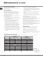
Conseils d’utilisation de l’appareil
Pour obtenir de meilleures performances de la table de
cuisson :
• Utiliser des casseroles à fond plat et de forte
épaisseur pour qu’elles adhèrent parfaitement à la
zone de chauffe
• Utiliser des casseroles dont le diamètre couvre
complètement la zone de chauffe de façon à ce que
toute la chaleur disponible puisse être utilisée.
• Veiller à ce que la base des casseroles soit toujours
parfaitement sèche et propre pour garantir un bon
contact et une longue durée de vie des foyers mais
Strona się ładuje...
Strona się ładuje...
Strona się ładuje...
Strona się ładuje...
Strona się ładuje...
Strona się ładuje...
Strona się ładuje...
Strona się ładuje...
Strona się ładuje...
Strona się ładuje...
Strona się ładuje...
Strona się ładuje...
Strona się ładuje...
Strona się ładuje...
Strona się ładuje...
Strona się ładuje...
Strona się ładuje...
Strona się ładuje...
Strona się ładuje...
Strona się ładuje...
Strona się ładuje...
Strona się ładuje...
Strona się ładuje...
Strona się ładuje...
Strona się ładuje...
Strona się ładuje...
Strona się ładuje...
Strona się ładuje...
Strona się ładuje...
Strona się ładuje...
Strona się ładuje...
Strona się ładuje...
Strona się ładuje...
Strona się ładuje...
Strona się ładuje...
Strona się ładuje...
Strona się ładuje...
Strona się ładuje...
Strona się ładuje...
Strona się ładuje...
Strona się ładuje...
Strona się ładuje...
Strona się ładuje...
Strona się ładuje...
Strona się ładuje...
Strona się ładuje...
Strona się ładuje...
Strona się ładuje...
Strona się ładuje...
Strona się ładuje...
Strona się ładuje...
Strona się ładuje...
Strona się ładuje...
Strona się ładuje...
Strona się ładuje...
Strona się ładuje...
Strona się ładuje...
Strona się ładuje...
Strona się ładuje...
Strona się ładuje...
-
 1
1
-
 2
2
-
 3
3
-
 4
4
-
 5
5
-
 6
6
-
 7
7
-
 8
8
-
 9
9
-
 10
10
-
 11
11
-
 12
12
-
 13
13
-
 14
14
-
 15
15
-
 16
16
-
 17
17
-
 18
18
-
 19
19
-
 20
20
-
 21
21
-
 22
22
-
 23
23
-
 24
24
-
 25
25
-
 26
26
-
 27
27
-
 28
28
-
 29
29
-
 30
30
-
 31
31
-
 32
32
-
 33
33
-
 34
34
-
 35
35
-
 36
36
-
 37
37
-
 38
38
-
 39
39
-
 40
40
-
 41
41
-
 42
42
-
 43
43
-
 44
44
-
 45
45
-
 46
46
-
 47
47
-
 48
48
-
 49
49
-
 50
50
-
 51
51
-
 52
52
-
 53
53
-
 54
54
-
 55
55
-
 56
56
-
 57
57
-
 58
58
-
 59
59
-
 60
60
-
 61
61
-
 62
62
-
 63
63
-
 64
64
-
 65
65
-
 66
66
-
 67
67
-
 68
68
-
 69
69
-
 70
70
-
 71
71
-
 72
72
-
 73
73
-
 74
74
-
 75
75
-
 76
76
-
 77
77
-
 78
78
-
 79
79
-
 80
80


HOTPOINT/ARISTON KRO 632 TD Z instrukcja
- Kategoria
- Płyty
- Typ
- instrukcja
- Niniejsza instrukcja jest również odpowiednia dla
w innych językach
- español: HOTPOINT/ARISTON KRO 632 TD Z Guía del usuario
- italiano: HOTPOINT/ARISTON KRO 632 TD Z Guida utente
- Deutsch: HOTPOINT/ARISTON KRO 632 TD Z Benutzerhandbuch
- português: HOTPOINT/ARISTON KRO 632 TD Z Guia de usuario
- français: HOTPOINT/ARISTON KRO 632 TD Z Mode d'emploi
- English: HOTPOINT/ARISTON KRO 632 TD Z User guide
- Nederlands: HOTPOINT/ARISTON KRO 632 TD Z Gebruikershandleiding
Powiązane artykuły
Inne dokumenty
-
Hotpoint-Ariston KRO 642 TO X Instrukcja obsługi
-
Whirlpool VRO 632 TD B instrukcja
-
Whirlpool KRO 632 TD X instrukcja
-
-
-
Whirlpool TRM 640.1 C instrukcja
-
Indesit VRA 641 D B instrukcja
-
-
Whirlpool VRA 641 DBS Instrukcja obsługi
-