
Zbiornik Buforowy
Pufferspeicher
CH buffer tank
Ballon tampon
Akumulācijas tvertnes
Буферные Накопители
SVK
DE
PL
EN
LV
FR
RU

2
Producent zastrzega sobie prawo wprowadzania zmian jakie będzie uważał
za wskazane, a które nie będą uwi docz nio ne w instrukcji obsługi, przy czym
zasadnicze cechy wyrobu zostaną za cho wa ne.
The manufacturer reserves the right to make changes to the product which are
not present in this manual instruction.
Der Hersteller behält sich das Recht vor, Änderungen am Produkt durchzuführen,
sofern die grundsätzlichen Eigenschaften und die Eignung des Standspeichers
für den Verwendungszweck unberührt bleiben.
Le fabricant réserve le droit de faire les changements nécessaires qui ne seront
pas mentionnés dans le mode d’emploi mais le caractéristique du produit sera
conservé.
Ražotājs no savas puses, bez brīdinājuma, atstāj tiesības veikt izmaiņas ierīces
uzbūvē, lai uzlabotu tās tehnoloģiskos un ekspluatācijas parametrus.
Производитель оставляет за собой право без уведомления потребите-
ля вносить изменения в конструкцию изделий для улучшения их техноло-
гических и эксплуатационных параметров.

3
PL;DE;EN;FR;LV;RU-104_f.1289
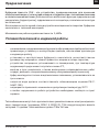
Zbiornik buforowy SVK jest urządzeniem przeznaczonym do magazynowania wody
grzewczej i/lub magazynu chłodu we współpracy z pompami ciepła i kotłami grzewczymi.
Dodatkowo pełnią funkcję rozdzielacza (sprzęgła), separatora hydraulicznego, obiegu
grzewczego od kotłowni.
Zbiornik buforowy wykonany jest z blachy stalowej czarnej, wewnątrz w stanie surowym.
Zbiornik SVK posiada izolację cieplną.
Maksymalne ciśnienie pracy zbiornika 0,6MPa
Przeznaczenie
- zapoznanie się z treścią niniejszej instrukcji obsługi umożliwi prawidłową instalację
i eksploatację urządzenia, zapewniając jego długotrwałą i niezawodną pracę,
- zainstalowanie i użytkowanie zbiornika buforowego niezgodne z niniejszą instrukcją
jest niedozwolone - grozi awarią i powoduje utratę gwarancji,
- urządzenia nie wolno instalować w pomieszczeniach, w których temperatura
otoczenia może obniżyć się poniżej 0°C,
- zamontowanie i uruchomienie zbiornika buforowego oraz wykonanie instalacji
towarzyszących należy powierzyć specjalistycznemu zakładowi usługowemu,
- bufor montuje się wyłącznie w pozycji stojącej, ustawiając go na trzech wkręcanych
stopkach.
- woda grzewcza powinna spełniać wymagania normy PN-C-04607:1993,
- nie wolno przekraczać temperatury znamionowej 95°C!
- wszelkie nieprawidłowości w pracy urządzenia należy zgłaszać do zakładu
serwisowego.
Warunki bezpiecznej i niezawodnej pracy
Wymienniki można dodatkowo wyposażyć w grzałkę elektryczną z termostatem
(np. GRW 1.4, GRW 2.0,..). Grzałkę należy wkręcić w miejsce korka 1½”.
Maksymalna długość grzałki 360 mm.
PL

4
3
4
5
6
1
2
A
B
272
100
0
118
171
ø592
7
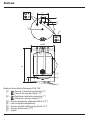
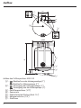
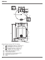
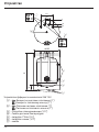
Budowa zbiornika buforowego SVK 100
[1] - Powrót z instalacji grzewczej (1")
Powrót do pompy ciepła (1”)
[2] - Zasilanie instalacji grzewczej (1”)
Zasilanie z pompy ciepła (1”)
[3] - króciec przyłącza odpowietrznika (1/2")
[4] - rurka czujnika temperatury
[5] - króciec grzałki elektrycznej (korek 1½”)
[6] - króciec spustowy (1/2”)
[7] - stopki
Budowa

5
PL;DE;EN;FR;LV;RU-104_f.1289
• Zbiornik buforowy montuje się wyłącznie w pozycji pionowej.
•
Zbiornik buforowy może być zamontowany w instalacji centralnego ogrzewania:
- systemu otwartego, wykonanej zgodnie z normą PN-B-02413:1991,
- systemu zamkniętego, wykonanej zgodnie z normą PN-B-02414:1999.
• Zbiornik musi być zamontowany w takim miejscu i w taki sposób, aby wyciek
awaryjny ze zbiornika lub przyłączy nie spowodował zalania pomieszczenia.
Instalacja
Przed uruchomieniem zbiornika buforowego należy optycznie sprawdzić prawidłowość
podłączenia urządzenia.
Sprawdzić szczelność połączeń. Sprawdzić działanie zaworu bezpieczeństwa (zgodnie
z instrukcją producenta zaworu).
Uruchomienie
PL
Recykling i usuwanie odpadów
Usuwanie produktu i wyposażenia:
Produktu ani wyposażenia nie wolno usuwać wraz z odpadami domowymi.
Należy zadbać, aby produkt i całe wyposażenie zostały usunięte w sposób prawidłowy.
Należy przestrzegać wszystkich obowiązujących przepisów.
Wycofanie z eksploatacji
Zużyty produkt nie może być traktowany jako odpad komunalny. Odpowiednie
zadysponowanie zużytego produktu zapobiega potencjalnym negatywnym wpływom
na środowisko jakie mogłyby wystąpić w przypadku niewłaściwego zagospodarowania
odpadów. W celu uzyskania bardziej szczegółowych informacji na temat recyklingu tego
produktu, należy skontaktować się z lokalną jednostką samorządu terytorialnego, ze
służbami zagospodarowania odpadów.

6
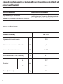
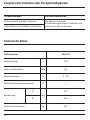
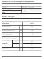
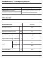
Zbiornik buforowy SVK 100
Pojemność znamionowa l 100
Ciśnienie znamionowe zbiornika MPa 0,6
Temperatura znamionowa °C 6 - 95
Minimalna temp. wody lodowej °C 6
Wymiary
A
mm
127
B 906
Masa (bez wody) kg 48
Dane techniczne
Sposób postępowania w przypadku wystąpienia uszkodzeń lub
nieprawidłowości
Nieprawidłowość Instrukcja postępowania
Wyciek wody ze zbiornika należy zakręcić zawory odcinające insta-
lacje CO i skontaktować się z serwisem
Nadmierny wzrost ciśnienia w zbiorniku

7
PL;DE;EN;FR;LV;RU-104_f.1289
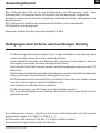
Der Pufferspeicher SVK ist für das Aufbewahren von Warmwasser und / oder
Kältespeicher, in Zusammenarbeit mit Kesseln und Wärmepumpen, vorgesehen.
Zusätzlich wirken sie als Verteiler (Kupplung), Hydraulikabscheider, Heizkreislauf aus
dem Heizraum.
Der Pufferspeicher besteht aus schwarzem Stahlblech, innen unbehandelt.
SVK-Speicher ist wärmeisoliert..
Maximaler Arbeitsdruck des Speichers beträgt 0,6 MPa.
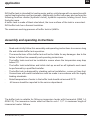
Anwendungsbereich
- Die Bedienungsanleitung ermöglicht eine richtige Installation und Nutzung, bzw.
sichert die dauerhafte und sichere Arbeit des Geräts.
- Unsachgemäße Montage und Nutzung des Speichers sind verboten, können
Störungen verursachen und zum Garantieverlust führen.
- Das Gerät darf nicht dort montiert werden, wo die Umgebungstemperatur unter 0°C
fallen kann.
- Die Montage und Inbetriebnahme des Speichers als auch alle Installationstätigkeiten
sollten von einem Fachhandwerker durchgeführt werden.
- Der Pufferspeicher darf ausschließlich in vertikaler Position montiert werden, indem
man ihn auf drei eingeschraubten Stellfüßen stellt.
- Das Heizwasser sollte die Normen erfüllen.
- Die Nenntemperatur von 95°C darf nicht überschritten werden!
- Alle Unregelmäßigkeiten beim Betrieb des Geräts sollten dem Servicecenter
gemeldet werden.
Bedingungen einer sicheren und zuverlässigen Nutzung
Die Pufferpeicher können zusätzlich mit einem Elektroheizstab mit Thermostat
ausgestattet werden (z.B. GRW 1.4, GRW 2.0, ...).
Der Heizstab sollte man am Platz des 1½” Korks installiert werden.
Die maximale Länge des Heizstabs ist 360 mm.
DE

8
3
4
5
6
1
2
A
B
272
100
0
118
171
ø592
7
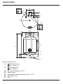
Aufbau
Aufbau des Pufferspeichers SVK 100
[1] - Rücklauf aus der Heizungsanlage (1")
Rücklauf zu Wärmepumpe (1”)
[2] - Versorgung der Heizungsanlage (1”)
Versorgung von der Wärmepumpe (1”)
[3] - Entlüfteranschluss (1/2")
[4] - Sensorrohr
[5] - Elektroheizstab-Stutzen (Kork 1½”)
[6] - Ablassanschluss (1/2”)
[7] - Stellfüsse

9
PL;DE;EN;FR;LV;RU-104_f.1289
• Der Pufferspeicher darf ausschlieslich in vertikaler Position montiert werden.
• Der Pufferspeicher kann in einer Heizinstallation montiert werden:
- eine offene Anlage gemäß Norm.
- eine geschlossene Anlage gemäß Norm.
• Der Speicher sollte an solchem Ort und auf bestimmte Weise montiert werden,
um eventuellen Wasseraustritt aus dem Behälter oder den Wasseranschlüssen im
Raum zu vermeiden.
Montage
Vor der Inbetriebnahme sollte man optisch die Anschlüsse des Geräts prüfen. Funktion
des Sicherheitsventils überprüfen (gemäß der Bedienungsanleitung des Ventilherstellers).
Inbetriebnahme
DE
Recycling und Entsorgung
Entfernung von Geräten und Zubehör:
Geräte und Zubehör dürfen nicht mit dem Hausmüll entsorgt werden.
Es sollte geachtet werden, dass das Produkt und alle Zubehörteile ordnungsgemäß
entsorgt werden.
Alle geltenden Gesetze müssen eingehalten werden.
Außerbetriebnahme
Das gebrauchte Produkt kann nicht als Siedlungsabfall behandelt werden. Eine
sachgerechte Entsorgung des gebrauchten Produkts verhindert mögliche negative
Umweltauswirkungen, die bei unsachgemäßer Entsorgung auftreten könnten. Für
detailliertere Informationen zum Recycling dieses Produkts wenden Sie sich bitte an
Ihre lokale Regierungsbehörde, Abfallentsorgungsdienst.

10
Pufferspeicher SVK 100
Nennkapazität l 100
Speicher-Nenndruck MPa 0,6
Nenntemperatur °C 6 - 95
Minimale Eiswassertemperatur °C 6
Bemessung
A
mm
127
B 906
Gewicht ohne Wasser kg 48
Technische Daten
Vorgehen bei Schäden oder Unregelmäßigkeiten
Unregelmäßigkeit Verfahrensanweisung
Wasseraustritt aus dem Speicher Die Absperrventile der
Zentralheizungsanlagen Schließen und
sich an den Service wenden.
Übermäßiger Druckaufbau im Speicher

11
PL;DE;EN;FR;LV;RU-104_f.1289
SVK buffer tank is intended for heating water and/or cold storage with co-opeartion with
central heating boilers and heat pumps. Additionally, buffer tanks may also perform the
following function: divider (hydraulic clutch), hydraulic seperator, heating circuit from
the boiler room.
A buffer tank is made of black steel sheet, the inner surface of the tank is a raw steel.
SVK buffer tank has a thermal insulation.
The maximum working pressure of buffer tank is 0,6MPa.
Application
- Read and strictly follow this assembly and operating instructions to ensure a long
life and reliable buffer tank operation.
- The manufacturer of this buffer tank will not be liable for any damages due to the
failure to follow this assembly and operating instructions.
- The buffer tank must not be installed in rooms where the temperature may drop
below 0°C.
- The buffer tank installation and initial start-up as well as all hydraulic work must
be performed by a quailied installer.
- The buffer tank is designed for standing vertical installation - screw on three feet.
- Connections with water installation must be made in accordance with the legally
binding standards.
- Rated temperature of water in the buffer tank should not exceed 95°C!
- All issues should be reported to the service department.
Assembly and operating instructions
The buffer tank is suitable for tting an immersion heater with thermostat (GRW 1.4,
GRW 2.0). The immersion heater must be tted in cork 1 1/2’’. A maximum length of
immersion heater: 360mm.
EN

12
Construction
3
4
5
6
1
2
A
B
272
100
0
118
171
ø592
7
Buffer tank SVK 100
[1] - CH return (1")
HP return (1”)
[2] - CH feed (1”)
HP feed (1”)
[3] - Air vent connection (1/2")
[4] - Sensor pipe
[5] - immersion heat connection (cork 1 1/2’’)
[6] - drainage (1/2’’)
[7] - feet

13
PL;DE;EN;FR;LV;RU-104_f.1289
• Buffer tank is designed for vertical mounting only (screw feet).
•
Buffer tank can be installed in the following central heating systems:
- open system, in accordance with legally binding requirements,
- closed system, in accordance with legally binding requirements.
• Buffer tank must be mounted in the place and in such a way to avoid room flooding
caused by leaking tank or connectors.
Installation
Check out the pipe connections and make sure that you observe the connection diagrams
before start-up.
Check out for water leaks. Check out the safety valve performance in accordance to
valve manufacturer’s instruction.
Start-up
EN
Recycling and waste disposal
Removal of product and equipment:
Do not dispose of the product or equipment with household waste. Make sure that the
product and all equipment is disposed of properly. Observe all applicable regulations.
Decomissioning
Used product must not be treated as a household waste. By disposing of this product
correctly you will help to prevent potential negative consequences for the environment
that could otherwise arise through inappropriate waste handling. For more detailed
information about recycling of this product, please contact your local authority waste
management service.

14
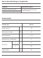
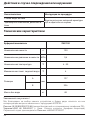
CH buffer tank SVK 100
Storage capacity l 100
Rated pressure storage MPa 0,6
Rated temperature °C 6 - 95
Minimum temp. of chilled water °C 6
Dimensions
A
mm
127
B 906
Weight (empty) kg 48
Technical data
How to deal with damage or irregularities
Irregularity Instructions for conduct
Leakage of water from the tank turn off the CH cut-off valves and
contact the service
Excessive pressure increase in the tank

15
PL;DE;EN;FR;LV;RU-104_f.1289
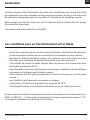
Le ballon tampon SVK est destiné à stocker de l’eau chauffante et/ou un dépôt du froid
en coopération avec des chaudières et des pompes de chaleur. En plus il a une fonction
de séparateur hydraulique entre la chaudière et l’installation du chauffage central.
Ballon tampon est fait de l’acier noir, brut à l’intérieur. Ballon tampon SVK est équipé
d’une isolation thermique.
La pression maximale du ballon est 0,6MPa.
Destination
- lire et suivre attentivement les instructions d’installation et d’utilisation an d’assurer
un fonctionnement performant et une durée de vie optimale de votre matériel,
- montage et utilisation de ballon tampon non conforme avec cette notice n’est pas
autorisée, peut provoquer un dysfonctionnement et annule la garantie,
- il est interdit de monter le ballon tampon dans les pièces où la température peut
descendre au dessous de 0°C,
- il faut demander le service spécialisé pour le montage, la réalisation des installations
nécessaires et le démarrage du ballon tampon,
- ballon tampon doit être posé uniquement en position verticale sur les trois pieds
à visser
- eau chauffante doit répondre aux normes en vigueur,
- il est interdit de dépasser la température nominale de 95°C!
- il faut signaler toutes les anomalies de fonctionnement à l’atelier de service.
On peut équiper les ballons tampos des résistances électriques avec thermostat (p.ex.
GRW 1,4, GRW 2,0, ...). Il faut visser la résistance électrique à la place du bouchon 1 1/2”.
La longueur maximale de la résistance est 360mm.
Les conditions pour un fonctionnement sûr et able
FR

16
Construction
3
4
5
6
1
2
A
B
272
100
0
118
171
ø592
7
Budowa zbiornika buforowego SVK 100
[1] - Retour chauffage (1")
Retour pompe à chaleur (1”)
[2] - Alimentation chauffage (1”)
Alimentation pompe à chaleur (1”)
[3] - Orice pour purgeur (1/2")
[4] - Doigt de gant
[5] - orice de résistance électrique (bouchon 1½”)
[6] - orice de vidange (1/2”)
[7] - pieds

17
PL;DE;EN;FR;LV;RU-104_f.1289
• Il faut poser le ballon tampon uniquement en position verticale.
• On peut utiliser le ballon tampon pour l’installation du chauffage central:
- dans le circuit ouvert, réalisé conformément aux normes en vigueur,
- dans le circuit fermé, réalisé conformément aux normes en vigueur,
• Le ballon tampon doit être installé de telle manière et dans tel endroit qu’au cas de
fuite accidentelle du ballon tampon ou des raccords il n’y avait pas d’inondation du
local.
Installation
Avant la première mise en service du ballon tampon il faut vérier visuellement la abilité
du montage de l’appareil. Vérier l’étanchéité des raccords. Vérier le fonctionnement
de la soupape de sécurité (conformément aux instructions du fabricant).
Première mise en service
FR
Recyclage et élimination des déchets
Enlèvement de produits et d’équipements:
Ce produit et ses accessoires ne doivent pas être jetés avec les ordures ménagères.
Assurez-vous que le produit et tous les accessoires ont été supprimés correctement.
Toutes les lois applicables doivent être respectées.
Retiré de l’exploitation
Le produit usé ne peut pas être traité comme un déchet municipal.
L’élimination appropriée du produit usé évite les effets négatifs potentiels sur
l’environnement, qui pourraient se produire en cas de gestion inappropriée des déchets.
Pour des informations plus détaillées sur le recyclage de ce produit, veuillez contacter
votre unité gouvernementale locale, service de gestion des déchets.

18
Ballon tampon SVK 100
Capacité nominale l 100
Pression nominale du cuve MPa 0,6
Température nominale °C 6 - 95
Température min. de l’eau glacée °C 6
Dimensions
A
mm
127
B 906
Poids sans eau kg 48
Données techniques
Procédure en cas de dommages ou d’irrégularités
Anomalie Instruction de procédure
Fuite d’eau du ballon Fermez les vannes d’arrêt du système de
chauffage central et contactez le service
Montée en pression excessive dans le
ballon

19
PL;DE;EN;FR;LV;RU-104_f.1289
Bufertvertne SVK ir ierīce, kas paredzēta apkures ūdens un/vai aukstuma uzglabāšanai
sadarbībā ar siltumsūkņiem un apkures katliem. Tas papildus kalpo kā sistēmas
hidrauliskais kontūru sadalītājs starp apkures loku un katlu. Tvertne izgatavota no metāla
loksnes, bez iekšēja pārklājuma. Akumulācijas tvertnes pieejamas ar termisko izolāciju.
Maksimālais darba spiediens tvertnei 0,6 MPa
Paredzētais pielietojums
- instrukcijā minēto lietošanas noteikumu ievērošana nodrošina ierīces pareizu
uzstādīšanu, kā arī ilgstošu un drošu to ekspluatāciju,
- neatbilstoša instrukcijai, akumulācijas tvertnes uzstādīšana un ekspluatācija nav
pieļaujama, jo var novest pie avārijas un garantijas zaudēšanas,
- akumulācijas tvertni nedrīkst uzstādīt telpā, kurā temperatūra zemāka par 0°C,
- akumulācijas tvertnes montāžu, kā arī ar to saistītos darbus jāveic specializētam
apkalpojošam personālam,
- tvertni uzstāda tikai vertikālā stāvoklī, balstot uz trīs kājiņām,
- apkures šķidrumam jāatbilst saistošiem standartiem,
- aizliegts pārsniegt nominālo pieļaujamo temperatūru 95°C !
- par visām ierīces darbības problēmām jāziņo servisa uzņēmumam.
Papildus tvertnēs var uzstādīt elektrisko tenu ar termostatu (piemēram GRW-1.4,
GRW-2.0). Tenu montē korķa ar izmēru 1½” vietā.
Elektriskā tena maksimālais garums – 360 mm.
Drošas un nepārtrauktas darbības lietošanas instrukcija
LV

20
Uzbūve
3
4
5
6
1
2
A
B
272
100
0
118
171
ø592
7
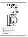
Akumulācijas tvertnes SVK 100 uzbūve
[1] - Atpakaļgaita apkures sistēmai (1")
Atpakaļgaita uz siltumsūkni (1”)
[2] - Turpgaita apkures sistēmai (1”)
Turpgaita no siltumsūkna (1”)
[3] - Atgaisotāja pieslēgums (1/2")
[4] - Termodevēja ieliktnis
[5] - pievienojuma uzmava tenam (1½”)
[6] - nolaišanas uzmava (1/2”)
[7] - kājas
Strona się ładuje...
Strona się ładuje...
Strona się ładuje...
Strona się ładuje...
Strona się ładuje...
Strona się ładuje...
Strona się ładuje...
Strona się ładuje...
-
 1
1
-
 2
2
-
 3
3
-
 4
4
-
 5
5
-
 6
6
-
 7
7
-
 8
8
-
 9
9
-
 10
10
-
 11
11
-
 12
12
-
 13
13
-
 14
14
-
 15
15
-
 16
16
-
 17
17
-
 18
18
-
 19
19
-
 20
20
-
 21
21
-
 22
22
-
 23
23
-
 24
24
-
 25
25
-
 26
26
-
 27
27
-
 28
28


w innych językach
- Deutsch: Kospel SVK Benutzerhandbuch
- français: Kospel SVK Manuel utilisateur