
Katherm HK
Montageanleitung
DE Montageanleitung
1
SAP 1521128 01/22
1 Übersicht
8
1
2
3
6
7
5
9
10
4
1
11
Katherm HK E
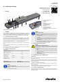
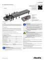
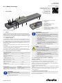
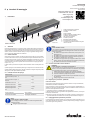
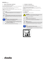
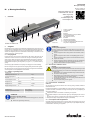
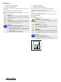
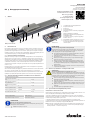
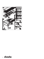
Katherm HK auf einen Blick
1 Anschluss- und Regelungsbox
2 Kondensatwanne
3 Konvektor
4 Roll-Rost
5 Montagehilfe, höhenverstellbar
6 EC-Querstromventilator
7 Filter (optionales Zubehör)
8 Bodenwanne
9 Trittstabile Höhenverstellung
10 Anbauset Kondensatpumpe
11 Konvektor mit integriertem Elektroheizstab und Si-
cherheitskette
2 Sicherheit
Dieser Abschnitt gibt einen Überblick über alle wichtigen Sicherheitsaspekte für den Schutz von
Personen. Neben den Sicherheitshinweisen in dieser und der weiterführenden Anleitung gemäß
QR-Code müssen die für den Einsatzbereich des Gerätes gültigen Sicherheits-, Arbeitsschutz-
und Umweltschutzvorschriften sowie den Hinweisen gemäß EN60335-1 eingehalten werden.
2.1 Bestimmungsgemäße Verwendung
Die Geräte dienen zum Heizen und/oder Kühlen für alle Gebäudebereiche, in denen im Winter
geheizt und im Sommer aufgrund hohen Sonneneinfalls durch Glasfronten gekühlt werden soll.
Das Gerät muss innerhalb des zu behandelten Raums an das bauseitige Heizungs- / Kälte- /Lüf-
tungssystem sowie das bauseitige Abwasser- und Stromnetz angeschlossen werden. Die Be-
triebs-und Einsatzgrenzen unter Kapitel 2.2 [}1] müssen eingehalten werden.
Zur bestimmungsgemäßen Verwendung gehört auch die Einhaltung aller Angaben in dieser An-
leitung.
Jede über die bestimmungsgemäße Verwendung hinausgehende oder andersartige Benutzung
gilt als Fehlgebrauch.
Jede Änderung am Gerät oder Verwendung von nicht originalen Ersatzteilen verursacht den Ver-
fall der Gewährleistung und die Haftung des Herstellers.
2.2 Betriebs- und Einsatzgrenzen
Betriebsgrenzen
Wassertemperatur min./max. °C 5-120
Luftansaugtemperatur min./
max. °C 15-40
Luftfeuchte min./max. % 15-75
Betriebsdruck min. bar/kPa -
Betriebsdruck max. bar/kPa 10/1000
Glykolanteil min./max. % 25-50
Betriebsspannung 230 V/ 50/60 Hz
Leistungs-/Stromaufnahme Auf dem Typenschild
HINWEIS!
Frostgefahr im Kaltbereich!
Bei Einsatz in unbeheizten Räumen besteht die Gefahr von Einfrieren des Wärme-
tauschers.
Das Gerät vor Frost schützen.
HINWEIS!
Gefahr bei Fehlgebrauch!
Bei Fehlgebrauch in untenstehenden Einsatzbereichen besteht die Gefahr der ein-
geschränkten bzw. ausfallenden Funktion des Geräts. Der Luftstrom muss unge-
hindert zirkulieren können.
Gerät niemals in Feuchträumen wie z.B. Schwimmbädern, Nassbereichen,
etc. betreiben.
Gerät niemals in Räumen mit explosionsfähiger Atmosphäre betreiben.
Gerät niemals in aggressiver oder korrosionsfördernder Atmosphäre (z.B.
Seeluft) betreiben.
Gerät niemals oberhalb von elektrischen Geräten (z.B. Schaltschränke,
Computer, elektrische Geräte, die nicht tropfwasserdicht sind) einsetzen.
Gerät niemals als Baustellenbeheizung verwenden.
2.3 Gefahren durch elektrischen Strom
GEFAHR!
Lebensgefahr durch elektrischen Strom!
Bei Berührung mit spannungsführenden Teilen besteht unmittelbare Lebensgefahr
durch Stromschlag. Beschädigung der Isolation oder einzelner Bauteile kann le-
bensgefährlich sein.
Arbeiten an der elektrischen Anlage nur von Elektrofachkräften ausführen
lassen.
Bei Beschädigungen der Isolation Spannungsversorgung sofort abschalten
und Reparatur veranlassen.
Feuchtigkeit von spannungsführenden Teilen fernhalten. Diese kann zum
Kurzschluss führen.
Gerät ordnungsgemäß erden.
2.4 Personalanforderungen - Qualifikationen
Fachkenntnisse
Die Montage dieses Produkts setzt Fachkenntnisse im Bereich Heizung, Kühlung, Lüftung, Instal-
lation und Elektrotechnik voraus.
Schäden, die aus einer unsachgemäßen Montage entstehen, hat der Betreiber oder Installateur
zu tragen. Der Installateur dieses Geräts soll aufgrund seiner fachlichen Ausbildung ausreichen-
de Kenntnisse besitzen über
Sicherheits- und Unfallverhütungsvorschriften
Länderspezifische Richtlinien und anerkannte Regeln der Technik, z. B. VDE-Bestimmungen,
DIN- und EN-Normen.
VDI 6022; zur Einhaltung der Hygieneanforderungen (falls erforderlich) ist eine Schulung des
Wartungspersonals nach Kategorie B (u.U. Kategorie C) notwendig.
2.5 Persönliche Schutzausrüstung
Persönliche Schutzausrüstung dient dazu, Personen vor Beeinträchtigungen der Sicherheit und
Gesundheit bei der Arbeit zu schützen. Grundsätzlich gelten die am Einsatzort geltenden Unfall-
verhütungsvorschriften.
Montage-, Installations- und
Betriebsanleitung:
Kampmann GmbH & Co. KG
Friedrich-Ebert-Str. 128-130
49811 Lingen (Ems)
T: +49591/7108 0
www.kampmann.de

Katherm HK
Montageanleitung
2
3 Transport, Lagerung und Verpackung
3.1 Allgemeine Transporthinweise
Die Lieferung bei Erhalt unverzüglich auf Vollständigkeit und Transportschäden prüfen.
Bei äußerlich erkennbarem Transportschaden wie folgt vorgehen:
Lieferung nicht oder nur unter Vorbehalt entgegennehmen.
Schadensumfang auf den Transportunterlagen oder auf dem Lieferschein des Transporteurs
vermerken.
Reklamation beim Spediteur einleiten.
HINWEIS!
Gewährleistungsansprüche können nur innerhalb der geltenden Reklamationsfris-
ten geltend gemacht werden. (Nähere Informationen unter den AGBs auf der
Kampmann Website)
HINWEIS!
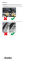
Zum Transport des Geräts sind 2 Personen erforderlich. Beim Transport persönli-
che Schutzkleidung tragen. Geräte nur beidseitig tragen und nicht an Leitungen/
Ventilen anheben.
HINWEIS!
Sachschäden durch unsachgemäßen Transport!
Bei unsachgemäßem Transport können Transportstücke fallen oder umstürzen.
Dadurch können Sachschäden in erheblicher Höhe entstehen.
Beim Abladen der Transportstücke, bei Anlieferung sowie bei innerbetriebli-
chem Transport vorsichtig vorgehen und die Symbole und Hinweise auf der
Verpackung beachten.
Nur die vorgesehenen Anschlagpunkte verwenden.
Verpackungen erst kurz vor der Montage entfernen.
4 Montage und Anschluss
4.1 Voraussetzungen an den Aufstellort
Das Gerät nur montieren, wenn folgende Bedingungen erfüllt sind:
Die sichere Aufhängung bzw. der sichere Stand des Geräts ist gewährleistet.
Der Luftstrom muss ungehindert zirkulieren können.
Bauseitig sind ausreichend dimensionierte Anschlüsse für den Wasserzu- und -ablauf vorhan-
den.
Bauseitig steht elektrische Energieversorgung zur Verfügung.
Falls notwendig, ist ein bauseitiger Kondensatanschluss mit ausreichendem Gefälle vorhan-
den.
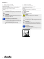
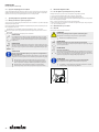
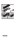
4.2 Mindestabstände
4.3 Montage
Für die Montage werden 2 Personen benötigt.
VORSICHT!
Verletzungsgefahr durch scharfe Gehäusebleche!
Die inneren Gehäusebleche besitzen zum Teil scharfe Kanten.
Schutzhandschuhe tragen.
HINWEIS!
Waagerechte Montage von Geräten!
Bei der Montage der Geräte auf eine exakt waagerechte Position des Geräts ach-
ten, um einen einwandfreien Betrieb zu gewährleisten.
HINWEIS!
Zugerscheinungen vermeiden!
Bei der Gerätemontage/ -aufhängung den Personenaufenthaltsbereich berück-
sichtigen. Personen nicht direktem Luftstrom aussetzen. Gerät entsprechend posi-
tionieren und ggf. Luftauslass einstellen.
HINWEIS!
Anschlüsse spannungsfrei montieren!
Anschlüsse müssen verspannungsfrei montiert werden!
Anschlussmutter mit einem geeigneten Werkzeug gegen Abscheren und
Verdrehen sichern.
29

Katherm HK
Montageanleitung
3
5 Prüfungen vor Erstinbetriebnahme
Im Zuge der Erstinbetriebnahme muss sichergestellt sein, dass alle notwendigen Voraussetzun-
gen erfüllt sind, damit das Gerät sicher und bestimmungsgemäß funktionieren kann.
Elektrische Prüfungen
Prüfen, ob alle Leitungen vorschriftsmäßig verlegt sind.
Prüfen, ob alle Leitungen den nötigen Querschnitt haben.
Prüfen, ob alle Adern gemäß den Elektroanschlussplänen aufgelegt sind.
Prüfen, ob der Schutzleiter durchgehend aufgelegt und verdrahtet ist.
Alle externen Elektroverbindungen und Klemmenanschlüsse auf festen Sitz prüfen, bei Be-
darf nachziehen.
Prüfen, ob DIP-Schalter gemäß Schaltplan richtig eingestellt sind.
Wasserseitige Prüfungen
Prüfen, ob alle Zu- und Ablaufleitungen ordnungsgemäß ausgeführt sind.
Rohrleitungen und Gerät mit Wasser füllen und entlüften.
Prüfen, ob alle Entlüftungsschrauben geschlossen sind.
Dichtigkeit prüfen (Abdrücken und Sichtprüfung).
Prüfen, ob eine Durchspülreinigung der wasserführenden Teile durchgeführt worden ist.
Prüfen, ob eventuell bauseitige Absperrventile geöffnet sind.
Prüfen, ob ein eventuell elektrisch angesteuertes Absperrventil korrekt angeschlossen ist.
Prüfen, ob alle Ventile und Stellantriebe fehlerfrei arbeiten (zulässige Einbaulage beachten).
Kondensatwasseranschluss
Prüfen, ob die Kondensatwanne frei von Bauschmutz ist.
Kondensatabfuhr und Verarbeitung der Alarmmeldung bei Kondensatpumpe prüfen.
Prüfen, ob das Kühlventil bei Alarmmeldung abschaltet.
Prüfen, ob das Gerät leckagefrei an den bauseitigen Kondensatanschluss angeschlossen ist.
Prüfen, ob die Abflussleitungen gereinigt und mit ausreichendem Gefälle verlegt sind.
Prüfen, ob vorhandene Kondensatpumpe mit elektrischer Spannung versorgt ist.
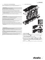
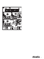
6 Kondensatwanne reinigen
1
2
2
4
4
4
5
5
6
7
3
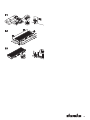
Rost 1 entfernen.
Abdeckbleche 2 entfernen.
Schelle vom Kondensatbogenstück lösen und Kondensatbogenstück vom Ablaufstutzen der
Kondensatwanne 3 abziehen.
Schrauben der Segmentbleche lösen und Segmentbleche 4 aus den Halterungen der Boden-
kanalwandungen entnehmen.
Motoranschlussstecker vom Querstromventilator abziehen.
Querstromventilator aus den Befestigungsbolzen 5 der Mittenwand 6 ziehen.
Schrauben der Mittenwand 6 lösen und Mittenwand aus dem Kanal herausnehmen.
Die unterhalb des Wärmetauschers angeordnete Kondensatwanne 7 bis zur raumseitigen
Kanalseite hervorziehen. Hinweis: Die Kondensatwanne ist nicht herausnehmbar!
Kondensatwanne 7 mit feuchtem Tuch reinigen und anschließend mit einem trockenen Tuch
feuchte Stellen beseitigen.
Nach dem Reinigen der Kondensatwanne die Bauteile in umgekehrter Reihenfolge zur De-
montage wieder montieren.

Katherm HK
Montageanleitung
4
Nach erfolgter Reinigung beim Einsetzen der Kondensatwanne folgende Hinweise
beachten:
Beim Montieren des seitlichen Niederhalters für die Kondensatwanne darauf achten, dass der
Niederhalter die Kondensatwanne gegen Hochdrücken und seitlich gegen Verschieben si-
chert.
Beim Wiedereinsetzen der Mittenwand darauf achten, dass die obere Abkantung über der Kon-
densatwanne montiert wird.

Katherm HK
Assembly instructions
EN Assembly instructions
5
SAP 1521128 01/22
1 Overview
8
1
2
3
6
7
5
9
10
4
1
11
Katherm HK E
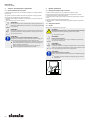
Katherm HK at a glance
1 Junction and control box
2 Condensate tray
3 Convector
4 Roll-up grille
5 Height adjustment feet
6 EC tangential fan
7 Filter (optional accessory)
8 Floor trench
9 Load-bearing height adjustment feet
10 Condensate pump mounting kit
11 Convector with integral electric coil and safety
chain
2 Safety
This section provides an overview of all important safety aspects for protecting personnel. In ad-
dition to the safety notes in this and the more detailed instruction in accordance with the QR
Code, the occupational health and safety and environmental protection regulations applicable to
the unit's field of application, as well as the notes in accordance with EN60335-1, must be ob-
served.
2.1 Correct use
The units are used for heating and/or cooling all areas of buildings that need to be heated in
winter and cooled in summer due to the high incidence of sunlight through the glass façades.
Within the room, the unit needs to be connected to the building's heating/cooling/ventilation
system and to the building's waste water and power network. The operating limits and limits of
use described in Chapter 2.2 [}5] must be observed.
Intended use of the unit also includes adherence to these instructions.
Any use beyond or other than the stated intended use is considered as misuse.
Any change to the unit or use of non-original spare parts will cause the expiry of the warranty
and the manufacturer’s liability.
2.2 Limits of operation and use
Limits of operation
Min./max. water temperature °C 5-120
Min./max. air intake temper-
ature °C 15-40
Min./max. air humidity % 15-75
Min. operating pressure bar/kPa -
Max. operating pressure bar/kPa 10/1000
Min./max. glycol percentage % 25-50
Operating voltage 230 V/ 50/60 Hz
Power/Current consumption On the type plate
IMPORTANT NOTE!
Danger of frost in cooling mode!
There is a risk of the heat exchanger freezing when used in unheated rooms.
Protect the unit from frost.
IMPORTANT NOTE!
Warning of misuse!
In the event of misuse, as itemised below, there is a danger of limited or failing
operation of the unit. Ensure that the airflow can circulate freely.
Never operate the unit in humid areas, such as swimming pools, wet areas
etc.
Never operate the unit in rooms with an explosive atmosphere.
Never operate the unit in aggressive or corrosive atmospheres (e.g. sea air).
Never operate the unit above electrical equipment (such as switch cabinets,
computers or other electrical units, or contacts that are not drip-proof).
Never use the unit as a construction site heater.
2.3 Risk from electrocution!
DANGER!
Risk of fatal injury from electrocution!
Contact with live parts will lead to fatal injury from electrocution. Damage to the
insulation or individual components can lead to a fatal injury.
Only permit qualified electricians to work on the electrical system.
Immediately disconnect the system from the power supply and repair it in
the event of damage to the insulation.
Keep live parts away from moisture. This can cause a short circuit.
Properly earth the unit.
2.4 Personnel requirements - Qualifications
Expertise
The installation of this product requires specialist knowledge of heating, cooling, ventilation, in-
stallation and electrical engineering.
Damage caused by improper installation is the responsibility of the operator or installer. The in-
staller of these units should have adequate knowledge of the following gained from specialist
professional training
Safety and accident prevention regulations
Country-specific guidelines and recognised technical regulations, i.e. Association of German
Electricians (VDE) regulations, DIN and EN standards.
VDI 6022; maintenance personnel must be trained to Category B (possibly Category C) to
comply with hygiene requirements (as required).
2.5 Personal Protective Equipment
Personal protective equipment is used to protect people from impaired safety and health when
working with the unit. The applicable accident prevention regulations at the place of use apply
in all cases.
Assembly, installation and operating
instructions:
Kampmann GmbH & Co. KG
Friedrich-Ebert-Str. 128-130
49811 Lingen (Ems)
T: +49591/7108 0
www.kampmann.de

Katherm HK
Assembly instructions
6
3 Transport, storage and packaging
3.1 General transport instructions
Check on delivery for completeness and transport damage.
Proceed as follows in the event of visible damage:
Do not accept delivery or only accept with reservations.
Record any transport damage on the transportation documents or on the transport company's
delivery note.
Submit a complaint to the freight forwarder.
IMPORTANT NOTE!
Warranty claims can only be made within the applicable period for complaints.
(More information is available in the T&Cs on the Kampmann website)
IMPORTANT NOTE!
2 people are needed to transport the unit. Wear personal protective clothing
when transporting the unit. Only lift the unit on both sides and not by the pipes /
valves.
IMPORTANT NOTE!
Material damage caused by incorrect transport!
Units being transported can drop or topple over if transported wrongly. This can
cause serious material damage.
Proceed carefully when unloading the equipment on delivery and when
transporting it on site and note the symbols and instructions on the pack-
aging.
Only use the holding points provided.
Only remove packaging shortly before assembling the unit.
4 Installation and wiring
4.1 Requirements governing the installation site
Only install and assemble the unit if the following conditions are met:
Make sure that the unit is securely suspended/standing.
Ensure that the airflow can circulate freely.
Provide for adequate space for floor and return water connections on site.
There is a power supply on site.
If need be, provide a condensation connection with a sufficient gradient on site.
4.2 Minimum clearances
4.3 Installation
2 people are needed to install the unit.
CAUTION!
Risk of injury from sharp metal housing!
The inner metal of the casing can have sharp edges.
Wear suitable protective gloves.
IMPORTANT NOTE!
Horizontal installation of units!
When installing the units, ensure that they are completely horizontal to ensure
proper operation.
IMPORTANT NOTE!
Avoid draughts!
Consider the occupied zone when installing/suspending the units. Do not expose
people to the direct air flow. Position the unit accordingly and adjust the air out-
let if required.
IMPORTANT NOTE!
Install connections in the de-energised state!
Connections must be installed without tension!
Use a suitable tool to protect terminal nuts from being sheared off and
twisted.
29

Katherm HK
Assembly instructions
7
5 Pre-commissioning checks
Before initial commissioning, check whether all the necessary conditions have been met so that
the unit can function safely and properly.
Electrical tests
Check whether all lines have been properly laid.
Check whether all lines have the necessary cross-section.
Are all wires connected in accordance with the electric wiring diagrams?
Is the earth wire connected and wired throughout?
Check all external electrical connections and terminal connections are fixed in place and
tighten if necessary.
Check whether DIP switches have been correctly set in accordance with the wiring diagram.
Water-side checks
Check whether all supply and drainage lines have been properly connected.
Fill pipes and unit with water and bleed.
Check whether all bleed screws are closed.
Check leak tightness (pressure test and visual inspection).
Check whether the parts carrying water have been flushed through.
Check whether any shut-off valves fitted on site are open.
Check whether any electrically actuated shut-off valves have been properly connected.
Check whether all valves and actuators are working properly (note permitted mounting pos-
ition).
Condensation water connection
Check whether the condensation tray is free of building rubble.
Check the condensation drain and operation of the alarm signal on the condensation pump.
Check whether the cooling valve switches off in the event of an alarm signal.
Check whether the unit is connected leak-free to the on-site condensation connection.
Check whether the waste water lines are clean and have a sufficient gradient.
Check whether the condensation pump has a working power supply.
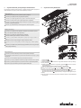
6 Cleaning the condensate tray
1
2
2
4
4
4
5
5
6
7
3
Remove the grille 1.
Remove the cover plates 2.
Loosen the clip from the condensate elbow and remove the condensate elbow from the drain
connection of the condensate tray 3.
Loosen the segment panel screws and the segment panels 4 from the brackets on the walls
of the floor trench.
Remove the motor connection plug from the tangential fan.
Remove the tangential fan from the fixing bolts 5 of the central wall 6.
Loosen the screws of the central wall 6 and remove the central wall from the trench.
Pull the condensate tray arranged below the condensate tray 7 to the room side of the
trench. Note: The condensate tray cannot be removed!
Use a damp cloth to clean the condensate tray 7 and then wipe away any damp patches
with a dry cloth.
After cleaning the condensate tray, refit the parts in reverse order to dismantling them.

Katherm HK
Assembly instructions
8
Note the following when inserting the condensate tray once it has been cleaned:
When inserting the side retainer for the condensate tray, make sure that the retainer prevents
the condensate try from pushing up and moving sidewards.
When reinserting the central wall, make sure that the upper edge is mounted above the con-
densate tray.

Katherm HK
Manuel de montage
FR Manuel de montage
9
SAP 1521128 01/22
1 Vue d’ensemble
8
1
2
3
6
7
5
9
10
4
1
11
Katherm HK E
Katherm HK en un coup d’œil
1 Boîtier de raccordement et de régulation
2 Bac à condensat
3 Convecteur
4 Grille à rouleaux
5 Aide de montage, réglable en hauteur
6 Ventilateur tangentiel EC
7 Filtre (accessoire en option)
8 Réservoir de fond
9 Réglage en hauteur pour résistance au piétinement
10 Kit de montage pompe à condensat
11 Convecteur avec élément chauffant électrique inté-
gré et chaîne de sécurité
2 Sécurité
La présente section offre un aperçu de l’ensemble des aspects de sécurité importants pour la
protection des personnes. Outre les consignes de sécurité du présent manuel et le manuel com-
plémentaire via code QR, il convient de respecter les consignes de sécurité, de sécurité au travail
et de protection de l’environnement, ainsi que les consignes de la norme EN60335-1, en vigueur
dans le secteur d’utilisation de l’appareil.
2.1 Utilisation conforme
Les appareils servent à chauffer et/ou refroidir toutes les parties des bâtiments nécessitant du
chauffage en hiver et de la fraîcheur en été en raison d’un fort ensoleillement dû à des baies vi-
trées. L’appareil doit être raccordé, dans la pièce à traiter, au système de chauffage/climatisa-
tion/ventilation du bâtiment, ainsi qu’au réseau d’évacuation des eaux usées et au réseau élec-
trique du bâtiment. Les limites de fonctionnement et d’emploi décrites au chapitre 2.2 [}9]
doivent être respectées.
L’utilisation conforme englobe également le respect de toutes les indications figurant dans le
présent manuel.
Toute utilisation allant au-delà des limites de l’utilisation conforme ou s’en éloignant de toute
autre façon est considérée comme une utilisation incorrecte.
Toute modification apportée à l’appareil ou utilisation de pièces de rechange autres que les
pièces d’origine entraîne la nullité de la garantie et dégage le fabricant de toute responsabilité.
2.2 Limites de fonctionnement et d’utilisation
Limites de fonctionnement
Température d’eau
min./max. °C 5-120
Température d’aspiration d’air
min./max. °C 15-40
Humidité de l’air min./max. % 15-75
Pression de fonctionnement
min. bar/kPa -
Pression de fonctionnement
max. bar/kPa 10/1000
Proportion de glycol
min./max. % 25-50
Tension de service 230V/ 50/60Hz
Puissance absorbée/consommation de cou-
rant Sur la plaque signalétique
AVERTISSEMENT!
Risque de gel dans la zone de froid!
En cas d’utilisation dans des pièces non chauffées, l’échangeur thermique risque
de geler.
Protéger l’appareil contre le gel.
AVERTISSEMENT!
Danger en cas d’utilisation incorrecte!
En cas d’utilisation incorrecte dans les secteurs d’utilisation mentionnés ci-des-
sous, l’appareil risque de fonctionner moins bien, voire de ne plus fonctionner du
tout. Le flux d’air doit pouvoir circuler sans obstacles.
Ne jamais faire fonctionner l’appareil dans des pièces humides comme les
piscines, zones sanitaires, etc.
Ne jamais faire fonctionner l’appareil dans des pièces ayant une atmo-
sphère explosible.
Ne jamais faire fonctionner l’appareil dans une atmosphère agressive ou
corrosive (par ex. air marin).
Ne jamais utiliser l’appareil au-dessus d’appareils électriques (par ex. ar-
moires électriques, ordinateurs, appareils électriques non étanches aux
gouttelettes).
N'utilisez jamais l'appareil comme chauffage de chantier.
2.3 Dangers dus au courant électrique
DANGER!
Danger de mort dû au courant électrique!
Tout contact avec des pièces sous tension constitue un danger de mort immédiat
par électrocution. Des dommages sur l’isolation ou sur des composants indivi-
duels peuvent constituer un danger de mort.
Les travaux sur l’installation électrique doivent être confiés à des électri-
ciens qualifiés.
Si l’isolation est endommagée, couper immédiatement l’alimentation en
tension et mandater quelqu’un pour la réparation.
Maintenir les pièces sous tension à l’abri de l’humidité. Celle-ci pourrait oc-
casionner un court-circuit.
Effectuer correctement la mise à la terre de l’appareil.
2.4 Critères d’exigence pour le personnel – Qualifications
Connaissances techniques
Le montage de ce produit présuppose des connaissances techniques dans le domaine du chauf-
fage, du refroidissement, de l’aération, de l’installation et de l’électrotechnique.
L’exploitant ou l’installateur est seul responsable des dommages résultant d’un montage non
conforme. En raison de sa formation professionnelle, l’installateur de cet appareil doit posséder
des connaissances suffisantes quant aux points suivants:
Consignes de sécurité et de sécurité au travail
Directives nationales et règles techniques reconnues, par ex. les disposition VDE, normes DIN
et EN.
VDI 6022; pour le respect des exigences en matière d’hygiène (le cas échéant), une formation
du personnel de maintenance est nécessaire selon la catégorie B (dans certaines circons-
tances, la catégorie C).
2.5 Équipement de protection individuelle
L’équipement de protection individuelle sert à protéger les personnes des atteintes à leur sécuri-
té et à leur santé pendant leur travail. Toujours respecter les consignes de prévention des acci-
dents en vigueur sur le lieu d’utilisation.
Manuel de montage, d'installation et
d'utilisation:
Kampmann GmbH & Co. KG
Friedrich-Ebert-Str. 128-130
49811 Lingen (Ems)
T: +49591/7108 0
www.kampmann.de

Katherm HK
Manuel de montage
10
3 Transport, stockage et emballage
3.1 Consignes de transport d’ordre général
Au moment de la réception, vérifier immédiatement que la livraison est complète et n’a pas été
endommagée pendant le transport.
Si des dommages dus au transport sont extérieurement visibles, procéder comme suit:
Ne pas accepter la livraison, ou seulement avec des réserves.
Noter l’étendue des dégâts sur les documents de transport ou sur le bordereau de livraison du
transporteur.
Faire une réclamation auprès du transporteur.
AVERTISSEMENT!
Les droits de garantie ne peuvent être reconnus que s’ils sont revendiqués dans
les limites du délai de réclamation applicable. (pour plus d’informations, consulter
les CGV sur le site Internet de Kampmann)
AVERTISSEMENT!
Il faut deux personnes pour transporter l’appareil. Porter une tenue de protection
individuelle pour le transport. Porter l’appareil uniquement par les deux côtés; ne
pas le soulever par les câbles/vannes.
AVERTISSEMENT!
Dommages matériels en cas de transport incorrect!
Un transport incorrect risque de faire tomber ou basculer les marchandises trans-
portées. Cela peut occasionner des dommages matériels considérables.
Procéder avec précaution lors du déchargement des marchandises, de la li-
vraison et du transport au sein de l’entreprise, et tenir compte des symboles
et indications figurant sur l’emballage.
Utiliser uniquement les points de fixation prévus à cet effet.
Attendre le moment du montage pour retirer l’emballage.
4 Montage et raccordement
4.1 Conditions sur le site d’installation
Ne monter l’appareil que si les conditions suivantes sont remplies:
La suspension sûre ou la stabilité de l’appareil est garantie.
Le flux d’air doit pouvoir circuler sans obstacles.
L’utilisateur doit prévoir des raccords suffisamment dimensionnés pour l’arrivée et l’évacua-
tion d’eau.
Une alimentation en énergie électrique est disponible sur le site.
Si nécessaire, un raccordement pour le condensat avec une inclinaison suffisante est dispo-
nible sur le site.
4.2 Distances minimales
4.3 Montage
Pour le montage, 2personnes sont nécessaires.
ATTENTION!
Risque de blessure due aux tôles coupantes du boîtier!
Les tôles internes du boîtier peuvent avoir des arêtes tranchantes.
Porter des gants de protection.
AVERTISSEMENT!
Montage horizontal d’appareils!
Lors du montage des appareils, veiller à un positionnement parfaitement horizon-
tal de l’appareil pour garantir un fonctionnement optimal.
AVERTISSEMENT!
Éviter les courants d’air!
Au moment de monter/suspendre l’appareil, tenir compte de la zone où se
trouvent des personnes. Ne pas exposer de personnes à un flux d’air direct. Posi-
tionner l’appareil en conséquence et régler la sortie d’air le cas échéant.
AVERTISSEMENT!
Monter les raccords hors tension!
Les raccords doivent être montés hors tension!
Sécuriser l’écrou de raccordement avec un outil adapté contre toute cou-
pure et toute déformation.
29

Katherm HK
Manuel de montage
11
5 Contrôles avant la première mise en service
Au cours de la première mise en service, il convient de s’assurer que toutes les conditions préa-
lables nécessaires sont remplies, afin que l’appareil fonctionne de manière sûre et conforme.
Contrôles électriques
Vérifier que tous les câbles sont posés conformément aux prescriptions.
Vérifier que tous les câbles ont la section requise.
Vérifier que tous les fils sont posés comme sur les schémas de raccordement électrique.
Vérifier que le conducteur de protection est posé et câblé en continu.
Vérifier que toutes les connexions électriques externes et tous les raccordements par bornes
sont bien branchés; les resserrer si nécessaire.
Vérifier que les commutateurs DIP sont réglés correctement selon le schéma de raccorde-
ment.
Contrôles côté eau
Vérifier que toutes les conduites d’amenée et d’évacuation sont montées correctement.
Remplir et purger les tuyaux et l’appareil d’eau.
Vérifier que toutes les vis de purge sont fermées.
Vérifier l’étanchéité (appuyer et effectuer un contrôle visuel).
Vérifier si les parties acheminant l’eau ont été rincées.
Vérifier, le cas échéant, si les vannes d’arrêt côté client sont restées ouvertes.
Vérifier, le cas échéant, que la vanne d’arrêt à commande électrique est correctement rac-
cordée.
Vérifier que toutes les vannes et tous les actionneurs fonctionnent parfaitement (respecter
la position de montage autorisée).
Raccord d’eau de condensation
Vérifier que le collecteur d’eau de condensation n’a pas été sali pendant les travaux.
Vérifier l’évacuation de l’eau de condensation et la mise en œuvre du signal d’alarme sur la
pompe d’eau de condensation.
Vérifier que la vanne de refroidissement se désactive en cas de signal d’alarme.
Vérifier que l’appareil est raccordé de façon étanche au raccord d’eau de condensation pré-
vu par le client.
Vérifier que les conduites d’évacuation sont propres et dotées d’une pente suffisante.
Vérifier que la pompe d’eau de condensation présente est alimentée en tension électrique.
6 Nettoyer le bac à condensat
1
2
2
4
4
4
5
5
6
7
3
Retirer la grille 1.
Retirer les tôles de recouvrement 2.
Défaire le collier de la pièce coudée du condensat et retirer la pièce coudée des tubulures
d’écoulement du bac à condensat 3.
Défaire les vis des tôles et retirer les tôles 4 des supports de parois de canal souterrain.
Retirer la connexion du raccordement moteur du ventilateur tangentiel.
Retirer le ventilateur tangentiel des boulons de fixation 5 de la paroi intermédiaire 6.
Défaire les vis de la paroi intermédiaire 6 et retirer la paroi intermédiaire du canal.
Tirer les bacs à condensat placés sous l’échangeur de chaleur 7 jusqu’à la face du canal cô-
té pièce. Remarque: Le bac à condensat n’est pas extractible!
Nettoyer le bac à condensat 7 à l’aide d’un chiffon humide puis essuyer les partie humides à
l’aide d’un chiffon sec.
Après avoir nettoyé le bac à condensat, remonter les composants dans l’ordre inverse du dé-
montage.

Katherm HK
Manuel de montage
12
Une fois le nettoyage effectué, respecter les consignes suivantes lors de la mise
en place du bac à condensat:
Lors du montage du dispositif de retenue latéral pour le bac de condensat, veiller à ce que le
serre-flan empêche le bac de condensat de se soulever et de se déplacer latéralement.
Lors de la remise en place de la paroi centrale, veiller à ce que le rebord supérieur soit monté au-
dessus du bac de condensat.

Katherm HK
Istruzioni di montaggio
IT Istruzioni di montaggio
13
SAP 1521128 01/22
1 Panoramica
8
1
2
3
6
7
5
9
10
4
1
11
Katherm HK E
Katherm HK in breve
1 Scatola di collegamento e regolazione
2 Vaschetta di raccolta condensa
3 Convettore
4 Griglia avvolgibile
5 Ausilio di montaggio, regolabile in altezza
6 Ventilatore a flusso trasversale EC
7 Filtro (accessorio opzionale)
8 Vaschetta a pavimento
9 Regolazione stabile dell'altezza
10 Kit di montaggio pompa condensa
11 Convettore con riscaldamento elettrico integrato e
catena di sicurezza
2 Sicurezza
Il presente paragrafo fornisce una panoramica di tutti gli aspetti legati alla sicurezza importanti
per la protezione delle persone. Unitamente alle avvertenze di sicurezza riportate in questo e ne-
gli altri manuali secondo il rispettivo codice QR è necessario osservare le prescrizioni in materia
di salute, sicurezza sul lavoro e ambiente valide per il campo di applicazione dell’apparecchio,
nonché le avvertenze stabilite dalla norma EN60335-1.
2.1 Utilizzo conforme
Gli apparecchi servono per riscaldare e/o raffrescare tutte le zone di edifici che vanno riscaldate
in inverno e raffrescate in estate, in quanto particolarmente esposte all'irradiazione solare per la
presenza di facciate di vetro. L'apparecchio, all'interno dell'ambiente da climatizzare, deve esse-
re collegato al sistema di riscaldamento/raffrescamento/ventilazione in loco, nonché alla rete fo-
gnaria ed elettrica. Devono essere rispettati i limiti di funzionamento e di impiego riportati nel
Capitolo 2.2 [}13].
L'utilizzo conforme prevede anche il rispetto di tutte le indicazioni contenute nelle presenti istru-
zioni.
Qualsiasi impiego che esula dall'utilizzo previsto oppure di tipo diverso è da considerarsi errato.
Qualsiasi modifica all'apparecchio oppure l’impiego di ricambi non originali comporta la perdita
della garanzia e della responsabilità del produttore.
2.2 Limiti di esercizio e di impiego
Limiti di esercizio
Temperatura dell'acqua min./
max. °C 5-120
Temperatura dell'aria aspirata
min./max. °C 15-40
Umidità dell'aria min./max. % 15-75
Pressione di esercizio min. bar/kPa -
Pressione di esercizio max. bar/kPa 10/1000
Percentuale di glicole min./
max. % 25-50
Tensione di esercizio 230 V / 50/60 Hz
Potenza/corrente assorbita Sulla targhetta identificativa
NOTA!
Pericolo di gelo in ambiente freddo!
In caso di impiego in locali non riscaldati vi è il rischio di congelamento dello
scambiatore di calore.
Proteggere l’apparecchio dal gelo.
NOTA!
Pericolo di utilizzo errato!
In caso di utilizzo errato negli ambiti indicati sotto sussiste il pericolo di funziona-
mento limitato o malfunzionamento dell'apparecchio. Il flusso d'aria deve poter
circolare senza ostacoli.
Non utilizzare mai l'apparecchio in ambienti umidi, come le piscine, in am-
bienti bagnati, ecc.
Non utilizzare mai l'apparecchio in locali esposti al rischio di esplosione.
Non utilizzare mai l'apparecchio in ambienti con atmosfera aggressiva o
che favorisce la corrosione (ad es. aria di mare).
Non utilizzare mai l'apparecchio sopra ad apparecchi elettrici (ad es. armadi
elettrici, computer, apparecchi elettrici non impermeabili al gocciolamento).
Non utilizzare mai l'unità come riscaldatore da cantiere.
2.3 Pericoli a causa della corrente elettrica!
PERICOLO!
Pericolo di morte a causa della corrente elettrica!
In caso di contatto con parti che conducono tensione vi è un pericolo immediato
di morte a causa di una possibile scossa elettrica. Un isolamento o singoli compo-
nenti danneggiati possono mettere a rischio la vita delle persone.
Affidare i lavori nell'impianto elettrico solo a elettricisti specializzati.
In caso di danneggiamenti dell'isolamento disinserire immediatamente l'ali-
mentazione di tensione e predisporre la riparazione.
Tenere le parti che conducono tensione al riparo dall'umidità. che può cau-
sare cortocircuiti.
Collegare l'apparecchio a massa in modo corretto.
2.4 Requisiti per il personale – Qualifiche
Conoscenze tecniche
Il montaggio di questo prodotto presuppone conoscenze tecniche nei campi di riscaldamento,
raffrescamento, ventilazione ed elettrotecnica.
I danni riconducibili a un montaggio improprio sono a carico del gestore o dell’installatore. L’in-
stallatore di questo apparecchio deve possedere conoscenze sufficienti maturate nel corso di un
percorso formativo specializzato concernente
le disposizioni di sicurezza e antinfortunistiche proprie del settore
Direttive specifiche per paese e regole della tecnica globalmente riconosciute, ad es. disposi-
zioni VDE, norme DIN e EN.
VDI 6022; per il rispetto dei requisiti igienici (se richiesto) è necessaria una formazione del
personale addetto alla manutenzione secondo la categoria B (eventualmente categoria C).
2.5 Equipaggiamento di protezione personale
L'equipaggiamento di protezione personale serve a proteggere le persone da pericoli per la sicu-
rezza e danni alla salute durante il lavoro. In linea di principio nel luogo di impiego si applicano
le prescrizioni vigenti contro gli infortuni.
Istruzioni di montaggio, installazione
e funzionamento:
Kampmann GmbH & Co. KG
Friedrich-Ebert-Str. 128-130
49811 Lingen (Ems)
T: +49591/7108 0
www.kampmann.de

Katherm HK
Istruzioni di montaggio
14
3 Trasporto, magazzinaggio e imballaggio
3.1 Avvertenze generali per il trasporto
Al momento della ricezione della consegna verificare immediatamente se il prodotto è integro e
se presenta danneggiamenti dovuti al trasporto.
In caso di danno da trasporto chiaramente riconoscibile, procedere come segue:
Non accettare la consegna o accettarla solo con riserva.
Annotare l'entità del danno sui documenti di trasporto o sulla bolla di consegna del traspor-
tatore.
Presentare reclamo allo spedizioniere.
NOTA!
È possibile avvalersi dei diritti di garanzia solo entro i termini previsti per il recla-
mo. (informazioni più dettagliate nelle CGC sul sito web di Kampmann).
NOTA!
Per il trasporto dell'apparecchio sono necessarie 2 persone. Per il trasporto indos-
sare l'equipaggiamento di protezione personale. Trasportare gli apparecchi affer-
randoli sempre da entrambi i lati e non sollevarli facendo presa su condotte/val-
vole.
NOTA!
Danni materiali a causa del trasporto non corretto!
In caso di trasporto non corretto gli oggetti trasportati possono cadere o ribaltar-
si. con conseguenti danni anche di notevole entità.
Quando si scaricano gli oggetti trasportati per una consegna e per un tra-
sporto interno allo stabilimento procedere con cautela e rispettare i simboli
e le avvertenze sull'imballaggio.
Utilizzare solo i punti di aggancio previsti.
Rimuovere gli imballaggi solo poco prima del montaggio.
4 Montaggio e collegamento
4.1 Requisiti per il luogo di installazione
Montare l'apparecchio solo se le condizioni seguenti sono soddisfatte:
Il fissaggio sospeso o il posizionamento dell’apparecchio in sicurezza sono garantiti.
Il flusso d'aria deve poter circolare senza ostacoli.
In loco sono presenti collegamenti di dimensioni adatte per l'alimentazione e lo scarico
dell'acqua.
Alimentazione elettrica disponibile in loco.
Se necessario è presente un attacco condensa in loco con una pendenza adeguata.
4.2 Distanze minime
4.3 Montaggio
Per il montaggio è richiesta la presenza di 2 persone.
ATTENZIONE!
Pericolo di lesioni a causa della lamiera dell'alloggiamento affilata!
La lamiera interna dell'alloggiamento presenta alcuni spigoli vivi.
Indossare guanti di protezione.
NOTA!
Montaggio orizzontale degli apparecchi!
Durante il montaggio, assicurarsi che gli apparecchi si trovino in posizione esatta-
mente orizzontale, al fine di garantire un funzionamento ottimale.
NOTA!
Evitare correnti d'aria!
Per il montaggio/montaggio sospeso degli apparecchi, considerare l’area di sosta
delle persone. Non esporre direttamente le persone alla corrente d’aria. Posizio-
nare l’apparecchio in modo corrispondente e regolare ev. l’uscita dell’aria.
NOTA!
Montare i collegamenti in assenza di tensione!
I collegamenti devono essere montati in assenza di tensioni meccaniche!
Fissare i dadi di collegamento con un attrezzo adeguato per non tranciarli o
ruotarli eccessivamente.
29

Katherm HK
Istruzioni di montaggio
15
5 Verifiche prima della prima messa in esercizio
Nel corso della prima messa in esercizio occorre accertarsi che tutti i requisiti necessari siano
soddisfatti in modo da garantire il funzionamento sicuro e conforme dell’apparecchio.
Controlli elettrici
Verificare se tutti i cavi sono posati come prescritto.
Verificare se tutti i cavi presentano la sezione trasversale necessaria.
Verificare se tutti i conduttori sono posati secondo gli schemi elettrici di collegamento.
Verificare se il conduttore di protezione è posato e cablato in modo continuo.
Verificare il fissaggio di tutti i collegamenti elettrici esterni e degli attacchi dei morsetti; ser-
rare all’occorrenza.
Verificare che gli interruttori DIP siano impostati correttamente secondo lo schema elettrico.
Controlli lato acqua
Verificare se tutte le linee di alimentazione e di scarico sono realizzate correttamente.
Riempire di acqua e sfiatare le tubazioni e l’apparecchio.
Verificare se tutte le viti di sfiato sono chiuse.
Controllare la tenuta (mediante caduta di pressione e ispezione visiva).
Verificare se è stata effettuata una pulizia tramite risciacquo dei componenti che conducono
acqua.
Verificare se eventuali valvole di intercettazione in loco sono aperte.
Verificare se un’eventuale valvola di intercettazione a comando elettrico è collegata corret-
tamente.
Verificare se tutte le valvole e gli attuatori funzionano correttamente (prestare attenzione
alla posizione di montaggio ammessa).
Attacco acqua di condensa
Verificare se la vaschetta di raccolta della condensa è priva di sporcizia da montaggio.
Verificare lo scarico della condensa e l'elaborazione del messaggio di allarme nella pompa
della condensa.
Verificare se la valvola raffrescamento si disattiva in caso di messaggio di allarme.
Verificare se l’apparecchio è collegato senza perdite all’attacco della condensa in loco.
Verificare se le condotte di scarico sono pulite e posate con una pendenza adeguata.
Verificare se la pompa della condensa presente è alimentata con tensione elettrica.
6 Pulizia della vaschetta di raccolta condensa
1
2
2
4
4
4
5
5
6
7
3
Rimuovere la griglia 1.
Rimuovere la lamiera di copertura 2.
Dopo averne allentato la fascetta, rimuovere la curva di raccordo per il passaggio della con-
densa dal manicotto di scarico della vaschetta di raccolta condensa 3.
Allentare le viti della lamiera segmentata ed estrarre quest'ultima 4 dai supporti delle pareti
dei canali a pavimento.
Staccare il connettore di attacco del motore dal ventilatore a corrente trasversale.
Rimuovere il ventilatore a corrente trasversale dai bulloni di fissaggio 5 della parete centra-
le 6.
Allentare le viti della parete centrale 6 ed estrarre quest’ultima dal canale.
Tirare la vaschetta di raccolta condensa posta sotto lo scambiatore di calore 7 fino al lato
del canale rivolto verso la stanza. Nota: la vaschetta di raccolta condensa non può essere
estratta!
Pulire la vaschetta di raccolta condensa 7 con un panno umido e successivamente asciugare
con un panno asciutto.
Dopo aver pulito la vaschetta di raccolta condensa rimontare i componenti procedendo in or-
dine inverso rispetto allo smontaggio.

Katherm HK
Istruzioni di montaggio
16
Al termine della pulizia, osservare le seguenti indicazioni per l’inserimento della
vaschetta di raccolta condensa:
Durante il montaggio del premilamiera laterale per la vaschetta di raccolta condensa accer-
tarsi che il premilamiera impedisca alla vaschetta di sollevarsi e spostarsi lateralmente.
Durante il reinserimento della parete centrale fare attenzione che la smussatura superiore venga
montata sopra la vaschetta di raccolta condensa.

Katherm HK
Montagehandleiding
NL Montagehandleiding
17
SAP 1521128 01/22
1 Overzicht
8
1
2
3
6
7
5
9
10
4
1
11
Katherm HK E
Overzicht van Katherm HK
1 Aansluit- en regelbox
2 Condensaatbak
3 Convector
4 Rolrooster
5 Montagehulpmiddel, in hoogte verstelbaar
6 EC-dwarsstroomventilator
7 Filter (optionele accessoire)
8 Bodembak
9 Stapveilige hoogteverstelling
10 Aanbouwset condensaatpomp
11 Convector met geïntegreerde elektrische verwar-
mingsstaaf en veiligheidsketen
2 Veiligheid
Dit hoofdstuk bevat een overzicht van alle belangrijke veiligheidsaspecten ter bescherming van
personen. Naast de veiligheidsinstructies in deze en de uitgebreidere handleiding volgens QR-co-
de moeten de voor de opstelplaats van het apparaat geldende veiligheidsvoorschriften, voor-
schriften voor veiligheid op het werk en voorschriften ter bescherming van het milieu en de aan-
wijzingen in EN 60335-1 worden opgevolgd.
2.1 Beoogd gebruik
De apparaten dienen voor het verwarmen en/of koelen van alle ruimtes in gebouwen die in de
winter moeten worden verwarmd en in de zomer door de hoge zoninval door glazen fronten
moeten worden gekoeld. Het apparaat moet in de betreffende ruimte worden aangesloten op
het bouwzijdige verwarmings-/koel-/ventilatiesysteem en op de bouwzijdige riolering en het
elektriciteitsnet. De bedrijfs- en gebruiksgrenzen in paragraaf 2.2 [}17] moeten worden op-
gevolgd.
Tot het beoogde gebruik behoort ook het opvolgen van alle gegevens in deze handleiding.
Elk ander verdergaand of ander gebruik dan het beoogde gebruik geldt als verkeerd gebruik.
Door elke verandering van het apparaat of door gebruik van niet-originele reserveonderdelen
vervalt de garantie en de aansprakelijkheid van de fabrikant.
2.2 Bedrijfs- en gebruiksgrenzen
Bedrijfsgrenzen
Watertemperatuur min./max. °C 5-120
Luchtaanzuigtemperatuur
min./max. °C 15-40
Luchtvochtigheid min./max. % 15-75
Bedrijfsdruk min. bar/kPa -
Bedrijfsdruk max. bar/kPa 10/1000
Glycolpercentage min./max. % 25-50
Bedrijfsspanning 230 V / 50/60 Hz
Vermogensopname/stroomverbruik Op het typeplaatje
AANWIJZING!
Vorstgevaar op koude plaatsen!
Bij gebruik in niet-verwarmde ruimtes bestaat bevriezingsgevaar van de warmte-
wisselaar.
Bescherm het apparaat tegen bevriezing.
AANWIJZING!
Gevaar bij verkeerd gebruik!
Bij verkeerd gebruik in de onderstaande situaties bestaat het gevaar dat het ap-
paraat slechts beperkt werkt of uitvalt. De luchtstroom moet onbelemmerd kun-
nen circuleren.
Gebruik het apparaat nooit in vochtige ruimtes zoals zwembaden, natte zo-
nes etc.
Gebruik het apparaat nooit in ruimtes waar ontploffingsgevaar kan heer-
sen.
Gebruik het apparaat nooit in agressieve of corrosiebevorderende omstan-
digheden (bv. zeelucht).
Gebruik het apparaat nooit boven elektrische apparaten (bv. schakelkasten,
computers, elektrische apparaten die niet druppelwaterbestendig zijn).
Gebruik het toestel nooit als bouwplaatsverwarming.
2.3 Gevaren door elektrische stroom
GEVAAR!
Levensgevaar door elektrische stroom!
Bij aanraking van onder spanning staande delen bestaat direct levensgevaar door
elektrocutie. Beschadiging van de isolatie of van afzonderlijke onderdelen kan le-
vensgevaarlijk zijn.
Werkzaamheden aan de elektrische installatie mogen uitsluitend door elek-
tromonteurs worden uitgevoerd.
Bij beschadiging van de isolatie moet de voedingsspanning onmiddellijk
worden uitgeschakeld en moet men dit laten repareren.
Voorkom dat vocht in de buurt van onder spanning staande delen komt. Dit
kan kortsluiting veroorzaken.
Zorg voor de juiste aarding van het apparaat.
2.4 Personeelseisen - kwalificaties
Vakkennis
Voor de montage van dit product is vakkennis van verwarming, koeling, ventilatie, installatie en
elektrotechniek vereist.
De exploitant of installateur is verantwoordelijk voor schade die door een ondeskundige monta-
ge worden veroorzaakt. De installateur van dit apparaat moet op basis van zijn vakopleiding vol-
doende kennis hebben van
veiligheidsvoorschriften en voorschriften ter voorkoming van ongevallen
landspecifieke richtlijnen en erkende technische regels, bijv. VDE-bepalingen, DIN- en EN-nor-
men.
VDI 6022; voor de naleving van hygiëne-eisen (indien nodig) is een opleiding van het onder-
houdspersoneel volgens categorie B (soms categorie C) noodzakelijk.
2.5 Persoonlijke beschermingsmiddelen
Persoonlijke beschermingsmiddelen dienen om personen tijdens het werk tegen gevaren voor de
veiligheid en gezondheid te beschermen. In principe gelden de op de gebruiksplaats toepasselij-
ke voorschriften ter voorkoming van ongevallen.
Montage-, installatie- en
gebruikershandleiding:
Kampmann GmbH & Co. KG
Friedrich-Ebert-Str. 128-130
49811 Lingen (Ems)
T: +49591/7108 0
www.kampmann.de

Katherm HK
Montagehandleiding
18
3 Transport, opslag en verpakking
3.1 Algemene transportinstructies
Bij ontvangst moet het geleverde product onmiddellijk op volledigheid en transportschade wor-
den gecontroleerd.
Ga bij aan de buitenkant herkenbare transportschade als volgt te werk:
Accepteer het geleverde product niet of alleen onder voorbehoud.
Noteer de schade op de transportdocumenten of het afleveringsbewijs van het transportbe-
drijf.
Dien een klacht in bij de expediteur.
AANWIJZING!
Garantieclaims kunnen alleen binnen de toepasselijke termijnen worden inge-
diend. (Nadere informatie is te vinden in de Algemene Voorwaarden op de
website van Kampmann)
AANWIJZING!
Voor het transport van het apparaat zijn 2 personen nodig. Draag tijdens het
transport persoonlijke beschermende kleding. Draag het apparaat alleen aan bei-
de zijden en til het niet aan de kabels/ventielen op.
AANWIJZING!
Materiële schade door ondeskundig transport!
Bij ondeskundig transport kunnen transportdelen eraf vallen of omvallen. Daar-
door kan aanzienlijke materiële schade ontstaan.
Bij het lossen van de transportdelen, bij levering en bij bedrijfsintern trans-
port moet men voorzichtig te werk gaan en op de symbolen en instructies
op de verpakking letten.
Gebruik alleen de daarvoor bestemde aanslagpunten.
Verwijder verpakkingen pas kort vóór de montage.
4 Montage en aansluiting
4.1 Voorwaarden voor de opstelplaats:
Monteer het apparaat alleen wanneer aan de volgende voorwaarden wordt voldaan:
De veilige ophanging resp. de veilige stand van het apparaat is gegarandeerd.
De luchtstroom moet onbelemmerd kunnen circuleren.
Bouwzijdig moeten voldoende grote aansluitingen voor de watertoe- en -afvoer aanwezig
zijn.
Bouwzijdig is een stroomvoorziening aanwezig.
Indien nodig, is een bouwzijdige condensaataansluiting met voldoende afschot aanwezig.
4.2 Minimumafstanden
4.3 Montage
Voor de montage zijn 2 personen nodig.
VOORZICHTIG!
Letselgevaar door scherpe behuizingsplaten!
De platen aan de binnenkant van de behuizing hebben gedeeltelijk scherpe ran-
den.
Draag veiligheidshandschoenen.
AANWIJZING!
Horizontale montage van apparaten!
Let er bij de montage van de apparaten op dat het apparaat precies horizontaal
staat om een goede werking te garanderen.
AANWIJZING!
Tocht vermijden!
Houd bij de montage/ophanging van het apparaat rekening met eventueel aan-
wezige personen. Stel geen personen bloot aan een directe luchtstroom. Positio-
neer het apparaat dienovereenkomstig en pas evt. de luchtuitstroomopening aan.
AANWIJZING!
Monteer aansluitingen spanningsvrij!
Aansluitingen moeten spanningsvrij worden gemonteerd!
Beveilig de aansluitmoer met geschikt gereedschap tegen afschuiven en
verdraaien.
29

Katherm HK
Montagehandleiding
19
5 Controles vóór eerste inbedrijfstelling
Bij de eerste inbedrijfstelling moet ervoor worden gezorgd dat aan alle noodzakelijke eisen is
voldaan, zodat het apparaat veilig en volgens het beoogde gebruik kan werken.
Elektrische controles
Controleer of alle kabels correct zijn aangelegd.
Controleer of alle kabels de vereiste diameter hebben.
Controleer of alle aders volgens de elektrische aansluitschema’s zijn aangesloten.
Controleer of de beschermingsleiding ononderbroken is aangesloten en bedraad.
Controleer of alle externe elektrische aansluitingen en klemaansluitingen goed vastzitten en
haal deze, indien nodig, aan.
Controleer of de DIP-schakelaars volgens het schakelschema zijn ingesteld.
Waterzijdige controles
Controleer of alle aanvoer- en afvoerleidingen goed zijn aangelegd.
Vul de leidingen en het apparaat met water en ontlucht deze.
Controleer of alle ontluchtingsschroeven gesloten zijn.
Voer een lektest uit (afdrukken en visuele inspectie).
Controleer of een doorspoelreiniging van de watervoerende delen is uitgevoerd.
Controleer of eventuele bouwzijdig afsluiters geopend zijn.
Controleer of een eventueel elektrisch aangestuurde afsluiter correct is aangesloten.
Controleer of alle kleppen/ventielen en stelaandrijvingen goed werken (let op de toegestane
inbouwpositie).
Condensaataansluiting
Controleer of de condensaatbak geen bouwafval bevat.
Controleer de condensaatafvoer en verwerking van de alarmmelding bij de condensaat-
pomp.
Controleer of het koelventiel bij een alarmmelding uitschakelt.
Controleer of het apparaat correct en zonder lekkage op de bouwzijdige condensaataanslui-
ting is aangesloten.
Controleer of de afvoerleidingen gereinigd en met voldoende afschot zijn aangelegd.
Controleer of de aanwezige condensaatpomp van stroom wordt voorzien.
6 Condensaatbak reinigen
1
2
2
4
4
4
5
5
6
7
3
Verwijder het rooster 1.
Verwijder de afdekplaten 2.
Maak de klem van het condensaatbochtstuk los en trek het condensaatbochtstuk van de af-
voerstomp van de condensaatbak 3 af.
Draai de schroeven van de segmentplaten los en verwijder dan de segmentplaten 4 uit de
houders van de bodemkanaalwanden.
Trek de motoraansluitstekker uit de dwarsstroomventilator.
Trek de dwarsstroomventilator uit de bevestigingsbouten 5 van de middenwand 6.
Draai de schroeven van de middenwand 6 los en verwijder de middenwand uit het kanaal.
Trek de onder de warmtewisselaar aangebrachte condensaatbak 7 tot aan het kanaal aan
de ruimtezijde naar voren. Opmerking: de condensaatbak kan niet worden verwijderd!
Reinig de condensaatbak 7 met een vochtige doek en droog dan vochtige plaatsen met een
droge doek.
Monteer, nadat de condensaatbak is gereinigd, de onderdelen weer in omgekeerde volgorde.

Katherm HK
Montagehandleiding
20
Na de reiniging moet bij het plaatsen van de condensaatbak op het volgende
worden gelet:
Bij het monteren van de aandrukker aan de zijkant voor de condensaatbak moet men erop
letten dat de aandrukker de condensaatbak tegen omhoog drukken en zijwaarts tegen ver-
schuiven beveiligt.
Bij het terugplaatsen van de middenwand moet men erop letten dat de bovenste kant boven de
condensaatbak wordt gemonteerd.
Strona się ładuje...
Strona się ładuje...
Strona się ładuje...
Strona się ładuje...
Strona się ładuje...
Strona się ładuje...
Strona się ładuje...
Strona się ładuje...
Strona się ładuje...
Strona się ładuje...
Strona się ładuje...
Strona się ładuje...
-
 1
1
-
 2
2
-
 3
3
-
 4
4
-
 5
5
-
 6
6
-
 7
7
-
 8
8
-
 9
9
-
 10
10
-
 11
11
-
 12
12
-
 13
13
-
 14
14
-
 15
15
-
 16
16
-
 17
17
-
 18
18
-
 19
19
-
 20
20
-
 21
21
-
 22
22
-
 23
23
-
 24
24
-
 25
25
-
 26
26
-
 27
27
-
 28
28
-
 29
29
-
 30
30
-
 31
31
-
 32
32


w innych językach
- italiano: Kampmann Katherm HK Guida d'installazione
- Deutsch: Kampmann Katherm HK Installationsanleitung
- français: Kampmann Katherm HK Guide d'installation
Powiązane artykuły
-
Kampmann Katherm QK Instrukcja instalacji
-
-
-
-
-
-
-
-
-