LD systems LD IMA 30 Mixing Amplifier Instrukcja obsługi
- Typ
- Instrukcja obsługi

USER´S MANUAL
BEDIENUNGSANLEITUNG
MANUEL D´UTILISATION
MANUAL DE USUARIO
INSTRUKCJA OBSŁUGI
MANUALE D´USO
IMA 30
INSTALLATION MIXING AMPLIFIER 30 W @ 4 OHMS / 100 V / 70 V
LDIMA30

CONTENTS / INHALTSVERZEICHNIS / CONTENU / CONTENIDO / TREŚĆ / CONTENUTO
ENGLISH
SAFETY INFORMATION 3
INTRODUCTION 5
CONNECTIONS, OPERATING AND DISPLAY ELEMENTS 5
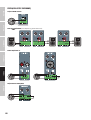
WIRING EXAMPLES 9
TERMINAL BLOCK CONNECTIONS 10
JUMPER FOR EMERGENCY SIGNAL ON AUX OUT 11
RACK MOUNTING 12
UNDER-TABLE MOUNTING 13
TECHNICAL DATA 14
MANUFACTURER´S DECLARATIONS 16
DEUTSCH
SICHERHEITSHINWEISE 17
EINLEITUNG 19
ANSCHLÜSSE, BEDIENUNG UND ANZEIGEELEMENTE 19
ANSCHLUSSBEISPIELE 23
KLEMMLEISTEN-ANSCHLÜSSE 24
JUMPER FÜR NOTFALLSIGNAL AN AUX OUT 25
RACK-MONTAGE 26
UNTERTISCH-MONTAGE 27
TECHNISCHE DATEN 28
HERSTELLERERKLÄRUNGEN 30
FRANCAIS
MESURES PRÉVENTIVES 31
INTRODUCTION 33
BRANCHEMENTS, FONCTIONNEMENT ET ÉLÉMENTS
DE L'AFFICHAGE 33
EXEMPLES DE CÂBLAGE 37
CONNEXIONS SUR LE BORNIER 38
CAVALIER POUR LE SIGNAL D'URGENCE SUR AUX OUT 39
MONTAGE EN RACK 40
MONTAGE SOUS UNE TABLE 41
DONNÉES TECHNIQUES 42
DECLARATIONS 44
ESPAÑOL
MEDIDAS DE SEGURIDAD 45
INTRODUCCIÓN 47
CONEXIONES, ELEMENTOS DE MANEJO Y ELEMENTOS
DE VISUALIZACIÓN 47
EJEMPLOS DE CABLEADO 51
CONEXIONES DEL BLOQUE DE TERMINALES 52
JUMPER PARA SEÑAL DE EMERGENCIA EN AUX OUT 53
MONTAJE EN RACK 54
MONTAJE BAJO MESA 55
DATOS TÉCNICOS 56
DECLARACIÓN DEL FABRICANTE 58
POLSKI
ŚRODKI OSTROŻNOŚCI 59
WPROWADZENIE 61
PRZYŁĄCZA, ELEMENTY OBSŁUGOWE I WSKAŹNIKI 61
PRZYKŁADOWE PODŁĄCZENIE PRZEWODÓW 65
PRZYŁĄCZA LISTWY ZACISKOWEJ 66
ZWORKA AWARYJNEGO SYGNAŁU DLA WYJŚCIA AUX OUT 67
MONTAŻ W SZAFIE RACK 68
MONTAŻ PODBLATOWY 69
DANE TECHNICZNE 70
DEKLARACJE PRODUCENTA 72
ITALIANO
MISURE PRECAUZIONALI 73
INTRODUZIONE 75
ELEMENTI DI COMANDO E DISPLAY 75
ESEMPI DI CABLAGGIO 79
RACCORDI PER MORSETTIERA 80
PONTE PER SEGNALE DI EMERGENZA SU AUX OUT 81
MONTAGGIO RACK 82
MONTAGGIO SOTTO TAVOLO 83
DATI TECNICI 84
DICHIARAZIONI DEL PRODUTTORE 86

3
DEUTSCHFRANCAIS
ESPAÑOL ENGLISH
ITALIANO POLSKI
ENGLISH
YOU‘VE MADE THE RIGHT CHOICE!
We have designed this product to operate reliably over many years. LD Systems stands for this with its name and many years of experience as
a manufacturer of high-quality audio products. Please read this User‘s Manual carefully, so that you can begin making optimum use of your LD
Systems product quickly.
You can nd more information about LD-SYSTEMS at our Internet site WWW.LD-SYSTEMS.COM
SAFETY INFORMATION
1. Please read these instructions carefully.
2. Keep all information and instructions in a safe place.
3. Follow the instructions.
4. Observe all safety warnings. Never remove safety warnings or other information from the equipment.
5. Use the equipment only in the intended manner and for the intended purpose.
6. Use only sufficiently stable and compatible stands and/or mounts (for fixed installations). Make certain that wall mounts are properly installed
and secured. Make certain that the equipment is installed securely and cannot fall down.
7. During installation, observ e the applicable safety regulations for your country.
8. Never install and operate the equipment near radiators, heat registers, ovens or other sources of heat. Make certain that the equipment is
always installed so that is cooled sufficiently and cannot overheat.
9. Never place sources of ignition, e.g., burning candles, on the equipment.
10. Ventilation slits must not be blocked.
11. Keep a minimum distance of 20 cm around and above the device.
12. Do not use this equipment in the immediate vicinity of water (does not apply to special outdoor equipment - in this case, observe the special
instructions noted below. Do not expose this equipment to flammable materials, fluids or gases. Avoid direct sunlight!
13. Make certain that dripping or splashed water cannot enter the equipment. Do not place containers filled with liquids, such as vases or drinking
vessels, on the equipment.
14. Make certain that objects cannot fall into the device.
15. Use this equipment only with the accessories recommended and intended by the manufacturer.
16. Do not open or modify this equipment.
17. After connecting the equipment, check all cables in order to prevent damage or accidents, e.g., due to tripping hazards.
18. During transport, make certain that the equipment cannot fall down and possibly cause property damage and personal injuries.
19.
If your equipment is no longer functioning properly, if fluids or objects have gotten inside the equipment or if it has been damaged in anot her
way, switch it off immediately and unplug it from the mains outlet (if it is a powered device). This equipment may only be repaired by authorized,
qualified personnel.
20. Clean the equipment using a dry cloth.
21. Comply with all applicable disposal laws in your country. During disposal of packaging, please separate plastic and paper/cardboard.
22. Plastic bags must be kept out of reach of children.
23. Please note that changes or modifications not expressly approved by the party responsible for compliance could void the user´s
authority to operate the equipment.
FOR EQUIPMENT THAT CONNECTS TO THE POWER MAINS
24. CAUTION: If the power cord of the device is equipped with an earthing contact, then it must be connected to an outlet with a protective ground.
Never deactivate the protective ground of a power cord.
25. If the equipment has been exposed to strong fluctuations in temperature (for example, after transport), do not switch it on immediately.
Moisture and condensation could damage the equipment. Do not switch on the equipment until it has reached room temperature.
26. Before connecting the equipment to the power outlet, first verify that the mains voltage and frequency match the values specified on the
equipment. If the equipment has a voltage selection switch, connect the equipment to the power outlet only if the equipment values and the
mains power values match. If the included power cord or power adapter does not fit in your wall outlet, contact your electrician.
27. Do not step on the power cord. Make certain that the power cable does not become kinked, especially at the mains outlet and/or power adapter
and the equipment connector.
28.
When connecting the equipment, make certain that the power cord or power adapter is always freely accessible. Always disconnect the equipment
from the power supply if the equipment is not in use or if you want to clean the equipment. Always unplug the power cord and power adapter from
the power outlet at the plug or adapter and not by pulling on the cord. Never touch the power cord and power adapter with wet hands.
29.
Whenever possible, avoid switching the equipment on and off in quick succession because otherwise this can shorten the useful life of the equipment.
30. IMPORTANT INFORMATION: Replace fuses only with fuses of the same type and rating. If a fuse blows repeatedly, please contact an authorised
service centre.
31. To disconnect the equipment from the power mains completely, unplug the power cord or power adapter from the power outlet.
32. If your device is equipped with a Volex power connector, the mating Volex equipment connector must be unlocked before it can be removed.
However, this also means that the equipment can slide and fall down if the power cable is pulled, which can lead to personal injuries and/or
other damage. For this reason, always be careful when laying cables.
33. Unplug the power cord and power adapter from the power outlet if there is a risk of a lightning strike or before extended periods of disuse.
34. The appliance is not to be used by persons (including children) with reduced physical, sensory or mental capabilities, or lack of experience
and knowledge.
35. Children must be instructed not to play with the device.
36. If the power cord of the device is damaged, do not use the device. The power cord must be replaced by an adequate cable or assembly from an
authorized service center.

4
ITALIANO
POLSKI
ESPAÑOL
FRANCAIS
DEUTSCHENGLISH
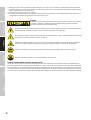
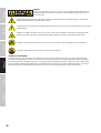
CAUTION:
To reduce the risk of electric shock, do not remove cover (or back). There are no user serviceable parts
inside. Maintenance and repairs should be exclusively carried out by qualified service personnel.
The warning triangle with lightning symbol indicates dangerous uninsulated voltage inside the unit, which may cause an
electrical shock.
The warning triangle with exclamation mark indicates important operating and maintenance instructions.
Warning! This symbol indicates a hot surface. Certain parts of the housing can become hot during operation. After use, wait for a
cool-down period of at least 10 minutes before handling or transporting the device.
Warning! This device is designed for use below 2000 metres in altitude.
Warning! This product is not intended for use in tropical climates.
CAUTION! HIGH VOLUMES IN AUDIO PRODUCTS!
This device is meant for professional use. Therefore, commercial use of this equipment is subject to the respectively applicable national accident
prevention rules and regulations. As a manufacturer, Adam Hall is obligated to notify you formally about the existence of potential health risks.
Hearing damage due to high volume and prolonged exposure: When in use, this product is capable of producing high sound-pressure levels (SPL)
that can lead to irreversible hearing damage in performers, employees, and audience members. For this reason, avoid prolonged exposure to
volumes in excess of 90 dB.
NOTE: This equipment has been tested and found to comply with the limits for a Class B digital device, pursuant to Part 15 of the FCC
Rules. These limits are designed to provide reasonable protection against harmful interference in a residential installation. This equipment genera-
tes, uses and can radiate radio frequency energy and, if not installed and used in accordance with the instructions, may cause
harmful interference to radio communications. However, there is no guarantee that interference will not occur in a particular installation. If this
equipment does cause harmful interference to radio or television reception, which can be determined by turning the equipment off and on, the
user is encouraged to try to correct the interference by one or more of the following measures:
– Reorient or relocate the receiving antenna.
– Increase the separation between the equipment and receiver.
– Connect the equipment into an outlet on a circuit different from that to which the receiver is connected.
– Consult the dealer or an experienced radio/TV technician for help.

5
DEUTSCHFRANCAIS
ESPAÑOL ENGLISH
ITALIANO POLSKI
INTRODUCTION
Permanent installations require solutions which offer a visually discrete design that blends into the background while still being flexible and
versatile in their functions. You need to be able to connect different audio sources and manage them, to mute non-priority signals during announ-
cements or emergency calls. With IMA® 30, LD Systems presents the first model of the new IMA® mixing amplifier-series, which leaves nothing to be
desired in terms of design and flexibility.
Seamless integration with IMA® 30 is a sure thing in both industrial and commercial applications thanks to the compact 9.5-inch housing design,
an array of connection possibilities, including Bluetooth for wireless connection of Audio and a multistage priority circuit. IMA® 30 is equipped with
four priority levels to manage all connected audio signals during emergency or priority announcements. An automatic standby mode can also be
activated to reduce power consumption during absence of audio signal.
The mixing amplifier features two priority contact closures: one for emergency input to mute both Mic/Line and music sources, and one for Mic/
Line Channels to mute music sources only. The outputs provide 30 W of power at 4 Ohm, a two-band equalizer for bass and trebles as well as 70
V/100 V tap settings. The Hi-Z and Lo-Z selector switch lets you separate the output signal completely from the output transformer to ensure an opti-
mal frequency response for low impedance applications. The built-in aux output can be used to add external power amplifiers, active subwoofers or
on-hold music systems to the IMA® 30. You can also choose to send the entire mix or only the selected music signal source to the aux output using
the music-mix selector switch.
FEATURES
• Line input for emergency signal with contact closure
• 2 microphone/line input sockets with microphone/line switch and switchable 24 V phantom power
• Switchable chime feature in Mic/Line 1 channel
• 2 line inputs with RCA (cinch) sockets and Bluetooth 4.0 interface (mono summed)
• Class-D amplifier with 30 W performance
• Output for low impedance speakers and 70 V/100 V outputs with LO-Z/HI-Z switch. The audio signal is completely separated from the transformers
for optimal frequency response during low impedance use.
• Balanced AUX line output for controlling external amplifiers, active subwoofers or music-on-hold systems
• Music mix switch on AUX out for setting whether AUX out plays the overall mix or only the selected music source.
• Separate tone control for treble and bass on the back of the device
• 4 priority settings for comprehensive integration options
• Switchable auto standby mode for reduction of energy consumption
• User-friendly control panel design for intuitive operation with capacitive control panels for selecting music source and for Bluetooth pairing
• Clearly arranged and labelled sockets and operating elements on the back for easy installation
• Universal wide-range switching power supply
• Half-rack format with 2 height units
• Rack mounting kit optionally available (IMA RK) for mounting one or two IMA 30/60 together in a single 19“ rack.
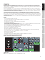
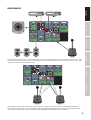
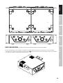
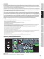
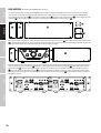
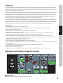
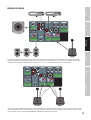
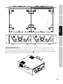
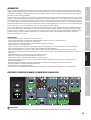
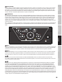
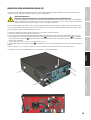
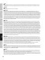
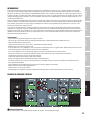
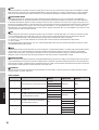
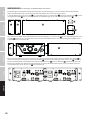
CONNECTIONS, OPERATING AND DISPLAY ELEMENTS
2
1
3XLR f
1
3
2
XLR m
2
6
3
9
10
578 4
1
1 POWER SOCKET
IEC power socket for supplying power to the device. A suitable power cable is included.

6
ITALIANO
POLSKI
ESPAÑOL
FRANCAIS
DEUTSCHENGLISH
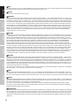
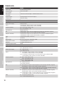
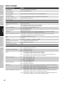
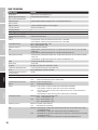
2 FUSE
Fuse holder for 250 V micro fuses (5 x 20 mm). IMPORTANT: Replace the fuse only with a fuse of the same type. Follow the instructions printed on the
housing. In the event of repeated fuse failure, please contact an authorised service centre.
3 ON/OFF
Rocker switch for switching the device on and off.
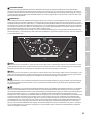
4 EMERGENCY
Five-pin terminal block connection for installing an acoustic emergency system. The pins +, - and G form the balanced line in. Pins C and + the con-
nection are for a separate mute switch (terminal block included). The VOX (Voice Operated Exchange) control allows users to set an audio threshold
for the emergency input to trigger an automatic mute circuit. When the emergency input level reaches that threshold, all other microphones and
line channels are muted to ensure that the emergency signal can be clearly and distinctly heard The EMERG display eld on the front of the device
is also lit. As soon as the emergency signal level drops below the dened threshold, the other channels are unmuted and the EMERG display eld
turns OFF. When set accordingly, the EMERGENCY channel has the highest priority among all channels. The emergency signal is sent directly to the
internal amplier and to the loudspeaker output. The master volume control has no inuence over the emergency signal. The emergency signal
volume is set using the GAIN control. The Emergency contact closure (pins C and +) allows muting of all other input channels, independently from
the VOX setup. If the VOX control is set to minimum (all the way left), the muting feature via the VOX circuit is deactivated and the EMERGENCY
channel can be used as a extra line channel.
5 MIC/LINE 1
Microphone/line channel with switchable chime feature. Both the combined XLR/jack combo socket or the terminal block connection can be used
as signal input. The pins +, - and G of the terminal block connection form the balanced input. Pins C and + the connection are for an external mute
button or switch (terminal block included). If a line signal is present at the combined XLR/jack combo socket or at the terminal block connector,
switch the MIC/LINE 1 channel to line sensitivity by depressing the corresponding MIC/LINE switch into the LINE position. If a microphone is attached,
set it in the non-depressed MIC position. When using a condenser microphone, also switch the 24 V phantom power on (switch PHANTOM ON/
OFF to the depressed ON position). Ensure that the microphone is already connected and that the channel’s volume is set to minimum before
switching the phantom power on. Before disconnecting the microphone, ensure that the phantom power is already switched off and that the
channel’s volume is set to minimum. The chime signal’s volume is set using the CHIME control. If the internal chime is triggered, channels MIC/LINE
1, MIC/LINE 2, and MUSIC are muted during the duration of the chime signal. The VOX control allows to set an audio threshold for MIC/LINE 1 input,
to trigger an automatic mute circuit that mutes MIC/LINE 2 and MUSIC channels as soon as the input level reaches the dened threshold. The VOX
control allows to set an audio threshold for MIC/LINE 1 input, to trigger an automatic mute circuit that mutes MIC/LINE 2 and MUSIC channels as
soon as the input level reaches the dened threshold. The PRIO LED in the front panel is turned ON when both the contact closure or the VOX circuit
are triggered. When the input signal level drops below the dened threshold, the channels are unmuted, and PRIO LED is turned OFF. When set
accordingly, the MIC/LINE 1 has priority over MIC/LINE 2 and MUSIC. Set the channel’s volume using control 1 on the front of the device.
6 MIC/LINE 2
Microphone/line channel. Either the RCA (cinch) sockets or the terminal block connection can be used as signal input. The pins +, - and G of the ter-
minal block connection form the balanced input (terminal block included). If a line level signal is present at the terminal block connection, switch
the MIC/LINE 2 channel to line sensitivity by depressing the corresponding MIC/LINE switch into the LINE position. If a microphone is attached to the
terminal block connection, set it to the non-depressed MIC position. When using a condenser microphone, also switch the 24 V phantom power on
(switch PHANTOM ON/OFF in the depressed ON position). Ensure that the microphone is already connected and that the channel’s volume is set to
minimum before switching the phantom power on. Before disconnecting the microphone, ensure that the phantom power is already switched off
and that the channel’s volume is set to minimum.
Tip: Use the contact closure (pins C and +) on MIC/LINE 1 channel to also give MIC/LINE 2 channel priority over MUSIC. External switches for both MIC/
LINE 1 and MIC/LINE 2 can be connected in parallel to the contact closure input.
7 MUSIC
Line channel for connecting additional playback devices such as a CD or MP3 player. A Bluetooth module is also built into the MUSIC channel. Two
stereo line input signals can be connected to the RCA (cinch) sockets available in the rear panel. One with a CD icon, and other with a cable icon.
Use
the touch-sensitive control on the front panel to select the desired signal source. Any stereo signals that are present are internally summed to mono.
8 AUX OUT
The AUX OUT line output with terminal block connection can be used, for example, to send a signal to an external amplier, an active subwoofer or a
MOH (Music On Hold) telephone system (terminal block included). The MUSIC-MIX switch allows sending of only the selected signal source from the
music channel (MUSIC position), or the full mix of all channels (MIX position).
Please note: The factory setting is that the EMERGENCY channel signal is routed to the AUX OUT line output with an internal jumper. To modify
this setting, the device must be opened and the corresponding jumper removed. To do so, please read the information found under “JUMPER FOR
EMERGENCY SIGNAL ON AUX OUT” in these instructions.
9 SPEAKER OUTPUT
The loudspeaker output with terminal block connection (terminal block included) offers the option to connect either a low impedance loudspeaker
with a total impedance of at least 4 ohm (switch LO-Z HI-Z to position LO-Z) or a 70 V/100 V loudspeaker (switch LO-Z HI-Z to position HI-Z). Please use
the corresponding pin assignment illustrated below the terminal block connection. Adjust the sound of the loudspeaker’s signal to your needs by
using the tone controls BASS and TREBLE. Please ensure that the total output of the connected loudspeaker roughly corresponds to the amplier
performance.

7
DEUTSCHFRANCAIS
ESPAÑOL ENGLISH
ITALIANO POLSKI
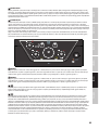
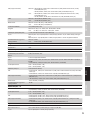
10 STANDBY ON/OFF
When the standby switch is activated (STANDBY in position ON), the amplier automatically goes into standby mode after 20 minutes of no audio
signal, thereby reducing power consumption. When an audio signal becomes present, standby mode is automatically ended and the amplier is
once again operational after around 3 seconds (the standby LED blinks white during this startup time). The STANDBY LED on the front of the device
is continuously white when in normal operation. It is red when in standby mode. IMA30 can be manually set into standby mode by pressing the
standby button on its front panel. In that case, the auto-standby mode is disabled, and the unit won’t wake up automatically.
Please note: The auto-standby mode switch analyses the connection status of the Bluetooth unit. If it identies a Bluetooth connection to a
playback device (e.g. smartphone or tablet), and Bluetooth is selected as a signal source, the device will not automatically go into standby mode.
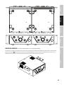
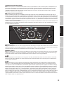
11
12
13 14
15
16
17 18
20
19
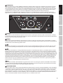
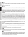
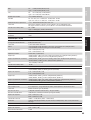
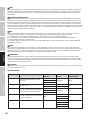
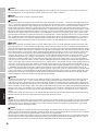
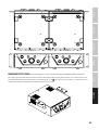
11 CHANNEL 1
Volume control for channel 1 with white SIG (signal) LED and red CLIP LED. If an audio signal is present on channel 1 and the volume is accordingly
increased using volume control 1, the white Signal LED lights up. If the red CLIP LED lights up, signal distortion may result. Reduce the output level of
the playback device or the volume using volume control 1.
12 CHANNEL 2
Volume control for channel 2 with white SIG (signal) LED and red CLIP LED. If an audio signal is present on channel 2 and the volume is accordingly
increased using volume control 2, the white Signal LED lights up. If the red CLIP LED lights up, signal distortion may result. Reduce the output level of
the playback device or the volume using volume control 2.
13
Touch-sensitive control button for selecting the MUSIC channel signal source (Bluetooth module, input with CD icon, input with cable icon). Switch
the signal source by touching the control panel for at least half a second. Activating the respective signal source occurs in a clockwise fashion.
14
Touch-sensitive control button for activating the Bluetooth pairing mode. Pair a Bluetooth playback device (e.g. smartphone, tablet etc.) with the
Bluetooth module by selecting Bluetooth as the signal source (see Item 13). If no playback device is paired or connected to the Bluetooth module,
the Bluetooth icon ashes slowly. Pair a device by pressing the Bluetooth control panel for around 2 seconds, until the Bluetooth icon ashes faster.
The Bluetooth ID is now visible to other Bluetooth devices. Activate Bluetooth on your playback device and search for nearby Bluetooth devices from
its Bluetooth menu. When LD IMA 30 appears under “available devices”, select it to automatically pair. When pairing is complete, the Bluetooth icon
on the front of the devices will light up and remain on. The Bluetooth ID is no longer visible to other devices to prevent unauthorised pairing with
the Bluetooth module. Playback on the device can now be started. To disconnect a currently paired Bluetooth device and to set the Bluetooth
module ready to pair again, press the Bluetooth icon for around 2 seconds. Pair the playback device and connect it again by selecting LD IMA 30
from “paired devices” in the Bluetooth menu of the playback device.
15 MUSIC
Volume control for the MUSIC channel with white SIG (signal) LED and red CLIP LED. If an audio signal is present on channel MUSIC and the volume is
accordingly increased using volume control MUSIC, the white Signal LED lights up. If the red CLIP LED lights up, signal distortion may result. Reduce
the output level of the playback device or the volume using MUSIC volume control.
16 MASTER VOLUME CONTROL
The master volume control is used for adjusting the volume of the summed signal of all channels, excluding the EMERGENCY channel. The EMERGEN-
CY channel bypasses the master volume control and its signal is sent directly to the internal amplier and loudspeaker output. The master volume
control features a display ring with tricolour LEDs. The LED ring is dark when no signal or when only a very weak signal is present at the output. It
lights up white when a signal with a sufcient level is present. When the internal limiter acts, the ring becomes yellow. When the ring becomes red,
protection mode is activated due to a technical problem (e.g. short circuit in speaker cable). The output is muted in protection mode. Switch the
device off. If the technical problem cannot be rectied, please contact an authorised service centre.

8
ITALIANO
POLSKI
ESPAÑOL
FRANCAIS
DEUTSCHENGLISH
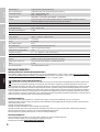
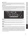
17 PRIO
Display eld for the indication of an active priority mode related to MIC/LINE channels (levels 2, 3 and 4). Three situations cause the priority feature
of the MIC/LINE channels to engage, thereby causing the PRIO display eld on the front of the device to light up yellow:
1. The VOX switching circuit is active (input signal level from channel MIC/LINE 1 exceeds the VOX threshold).
2. Contact between C and + in the terminal block connection of channel MIC/LINE1 is closed using a mute button or switch.
3. Chime tone is being played.
Further information about channel priorities and the display elds EMERG and PRIO, on the front of the device, can be found in the table PRIORITY
LEVELS in these instructions.
18 EMERG
Display eld for the priority feature of the Emergency channel. The display eld EMERG will light up yellow when priority level 1 is activated by an
emergency VOX circuit or by using an attached mute switch (contact closure). In that moment, all other input channels will be muted. As soon as the
contact closure is opened/disconnected, and when the emergency signal level falls below the set VOX threshold, all channels will be unmuted, and
the EMERG display will be turned off.
19 STANDBY BUTTON
The amplier can be set to standby mode with a short push of the standby button. This also mutes the loudspeaker outputs. Bring the device out of
standby and back into normal operation by briey pressing the button again. When standby mode is activated by pressing the standby button, the
amplier’s standby mode cannot be ended by the automatic standby feature, even when an audio signal is present.
20 STANDBY LED
Bicolour LED for displaying operational status. The standby LED lights up white when the device is operational. In standby mode it lights up red.
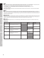
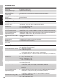
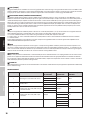
PRIORITY LEVELS
Priority Level Trigger Source Muted Signal Sources Active Signal
Sources
Indication in the
Front Panel
1 Emergency VOX & contact closure
MIC/LINE 1
EMERGENCY EMERGMIC/LINE 2
MUSIC
2MIC/LINE 1 VOX MIC/LINE 2 EMERGENCY PRIO
MUSIC MIC/LINE 1
3MIC/LINE 1 contact closure during
chime playout
MIC/LINE 1
EMERGENCY PRIOMIC/LINE 2
MUSIC
4MIC/LINE 1 contact closure after
chime playout MUSIC
EMERGENCY
PRIOMIC/LINE 1
MIC/LINE 2
5– –
EMERGENCY
–
MIC/LINE 1
MIC/LINE 2
MUSIC

9
DEUTSCHFRANCAIS
ESPAÑOL ENGLISH
ITALIANO POLSKI
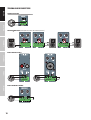
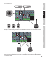
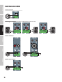
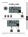
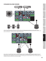
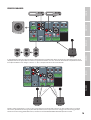
WIRING EXAMPLES
Microphone Signal
Microphone Signal
Mute Contact
Mute Contact
12
The connection for a mute button or switch in the MIC/LINE 1 channel can be used by two devices at the same time for muting a music signal
or initiating the chime signal. To do so, the corresponding mute contacts of both devices must be connected to the contacts C and + of the
terminal block connection of the MIC/LINE 1 channel.
Microphone Signal
Microphone Signal
Mute Contact
Mute Contact
12
When wiring the terminal block, please ensure that the correct pin assignment is observed (see illustration below the terminal block
connections). The manufacturer assumes no liability for damage of any kind resulting from incorrect wiring! Further information on the
correct wiring of terminal blocks can be found under the item TERMINAL BLOCK CONNECTIONS in these instructions.

10
ITALIANO
POLSKI
ESPAÑOL
FRANCAIS
DEUTSCHENGLISH
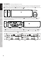
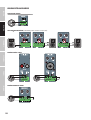
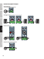
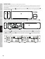
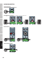
TERMINAL BLOCK CONNECTIONS
LINE OUTPUT AUX OUT
2
1
3XLR f
1
3
2
XLR m
SPEAKER CONNECTIONS (low impedance, 100 V and 70 V loudspeakers)
2
1
3XLR f
1
3
2
XLR m
2
1
3XLR f
1
3
2
XLR m
2
1
3XLR f
1
3
2
XLR m
INPUTS CHANNELS 1 AND 2
2
1
3XLR f
1
3
2
XLR m
2
1
3XLR f
1
3
2
XLR m
INPUTS EMERGENCY CHANNEL
2
1
3XLR f
1
3
2
XLR m

11
DEUTSCHFRANCAIS
ESPAÑOL ENGLISH
ITALIANO POLSKI
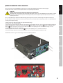
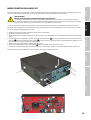
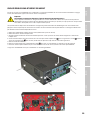
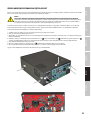
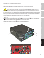
JUMPER FOR EMERGENCY SIGNAL ON AUX OUT
The factory setting is that the EMERGENCY channel signal is routed to the AUX OUT line output with an internal jumper.
To modify this setting, the device must be opened and the corresponding jumper removed.
Important!
Warning: Risk of electric shock! Dangerous voltages present inside device!
Opening the device and modifying the conguration with jumpers requires specialist knowledge and may only be carried out
by specially trained personnel! If you are not suitably qualied, do not attempt the procedure yourself. Refer instead to a
qualied professional.
Take care when opening the amplier and when modifying the conguration, in order to avoid damage to the amplier and injury to
persons. Follow each step of the instructions exactly. The manufacturer shall not be liable for any damage to devices or injury to persons
resulting from improper handling!
1. Fully disconnect the amplier from the mains (pull out the mains plug)!
2. Disconnect all cables from the amplier.
3. In order to be sure than no dangerous voltage is still present inside the amplier, wait for at least 1 minute before opening the housing!
4. Loosen and remove the 2 screws on each side of the amplier A , the 4 labelled screws on the back B and one screw on top of the
amplier C with a suitable tool (9 screws in total). Make a note of the corresponding positions for the 3 different types of screw.
5. Pull the housing lid backwards off the housing.
6. Pull the jumpers indicated in the second picture D from the corresponding contacts (interior back of device).
7. Push the housing lid from the back on to the housing and screw it closed with the previously removed screws.
The EMERGENCY channel’s signal is now no longer routed to the line output AUX OUT.
A
AB
D
B
C

12
ITALIANO
POLSKI
ESPAÑOL
FRANCAIS
DEUTSCHENGLISH
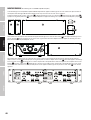
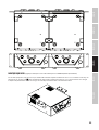
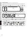
RACK MOUNTING (rack mounting kit LDIMARK optionally available)
The optionally available rack mounting kit LDIMARK includes rack-mount brackets and connectors for installing a single IMA 30 installation
mixing amplier, as well as for adjacently installing two ampliers in a 19” rack. The set includes: 2x rack-mount brackets with short sides
A , 1x rack-mount bracket with long sides B , 2x small plates for the back C , 2x rectangular plates for the bottom D , 4x M4 at-headed
screws for the rack-mount brackets, 8x M3 countersunk screws for plate D .
AA B
C
D
Installing a single amplier requires a rack-mount bracket with short sides A and the rack-mount bracket with long sides B . Screw the
bracket with the short sides to the left or right side of the amplier and the bracket with the long side on to the opposite side. Use the
included M4 at-headed screws for this.
AB
To install two ampliers alongside each other in a 19” rack, you will need the two small plates to join for connecting the ampliers on the
back C , the two rectangular plates to join the ampliers on the bottom D and the two rack-mount brackets with short sides A . Loosen
the screws on the back at the corresponding positions and use them to screw on the plates C . Screw the connectors D , as illustrated
below, on to the corresponding positions on the ampliers with the included M3 countersunk screws. Use the M4 at-headed screws to
screw the rack-mount brackets with the short sides A on to the sides of the devices.
V1
05.06.2019
PRODUCTNAME
A A
B B
C C
D D
E E
F F
G G
H H
J J
K K
L L
M M
N N
P P
R R
T T
24
24
23
23
22
22
21
21
20
20
19
19
18
18
17
17
16
16
15
15
14
14
13
13
12
12
11
11
10
10
9
9
8
8
7
7
6
6
5
5
4
4
3
3
2
2
1
1
NOT SPECIFIED
ld-ima30 20190219_asm (2).stp
GEWICHT:
A0
BLATT 1 VON 1
MASSSTAB:1:1
ZEICHNUNGSNR.
BENENNUNG:
ÄNDERUNG
ZEICHNUNG NICHT SKALIEREN
WERKSTOFF:
DATUM
SIGNATUR
NAME
ENTGRATEN
UND SCHARFE
KANTEN
BRECHEN
OBERFLÄCHENGÜTE:
WENN NICHT ANDERS DEFINIERT:
BEMASSUNGEN SIND IN MILLIMETER
OBERFLÄCHENBESCHAFFENHEIT:
TOLERANZEN:
LINEAR:
WINKEL:
QUALITÄT
PRODUKTION
GENEHMIGT
GEPRÜFT
GEZEICHNET
A
C
C
A

13
DEUTSCHFRANCAIS
ESPAÑOL ENGLISH
ITALIANO POLSKI
V1
05.06.2019
PRODUCTNAME
A A
B B
C C
D D
E E
F F
G G
H H
J J
K K
L L
M M
N N
P P
R R
T T
24
24
23
23
22
22
21
21
20
20
19
19
18
18
17
17
16
16
15
15
14
14
13
13
12
12
11
11
10
10
9
9
8
8
7
7
6
6
5
5
4
4
3
3
2
2
1
1
NOT SPECIFIED
ld-ima30 20190219_asm (2).stp
GEWICHT:
A0
BLATT 1 VON 1
MASSSTAB:1:1
ZEICHNUNGSNR.
BENENNUNG:
ÄNDERUNG
ZEICHNUNG NICHT SKALIEREN
WERKSTOFF:
DATUM
SIGNATUR
NAME
ENTGRATEN
UND SCHARFE
KANTEN
BRECHEN
OBERFLÄCHENGÜTE:
WENN NICHT ANDERS DEFINIERT:
BEMASSUNGEN SIND IN MILLIMETER
OBERFLÄCHENBESCHAFFENHEIT:
TOLERANZEN:
LINEAR:
WINKEL:
QUALITÄT
PRODUKTION
GENEHMIGT
GEPRÜFT
GEZEICHNET
D
D
V1
05.06.2019
PRODUCTNAME
A A
B B
C C
D D
E E
F F
G G
H H
J J
K K
L L
M M
N N
P P
R R
T T
24
24
23
23
22
22
21
21
20
20
19
19
18
18
17
17
16
16
15
15
14
14
13
13
12
12
11
11
10
10
9
9
8
8
7
7
6
6
5
5
4
4
3
3
2
2
1
1
NOT SPECIFIED
ld-ima30 20190219_asm (2).stp
GEWICHT:
A0
BLATT 1 VON 1
MASSSTAB:1:1
ZEICHNUNGSNR.
BENENNUNG:
ÄNDERUNG
ZEICHNUNG NICHT SKALIEREN
WERKSTOFF:
DATUM
SIGNATUR
NAME
ENTGRATEN
UND SCHARFE
KANTEN
BRECHEN
OBERFLÄCHENGÜTE:
WENN NICHT ANDERS DEFINIERT:
BEMASSUNGEN SIND IN MILLIMETER
OBERFLÄCHENBESCHAFFENHEIT:
TOLERANZEN:
LINEAR:
WINKEL:
QUALITÄT
PRODUKTION
GENEHMIGT
GEPRÜFT
GEZEICHNET
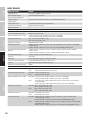
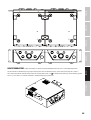
UNDER-TABLE MOUNTING (rack-mount bracket included in optionally available rack mounting kit LDIMARK).
For under-table mounting, there are two M4 screw holes located on the upper edge of both sides of the housing. Use the included M4
at-headed screws to tightly screw the two rack-mount brackets A with short sides to each side of the housing as illustrated. The ampli-
er can now be attached in a suitable position below a desktop.
A
A

14
ITALIANO
POLSKI
ESPAÑOL
FRANCAIS
DEUTSCHENGLISH
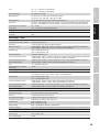
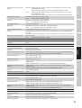
TECHNICAL DATA
Item number LDIMA30
Product type Installation mixing amplier
Emergency input 1 balanced line input
Mic/Line inputs 2
Music sources 2 unbalanced stereo line inputs + 1 Bluetooth interface v4.0
Line outputs 1
Powered outputs 1 with output mode selector (Low-Z/High-Z)
Cooling system Convection cooling
Priority levels 4
Emergency Input
Nominal input sensitivity -6 dBu (Sine 1 kHz, Gain max)
Nominal input clipping 20 dBu (Sine 1kHz)
THD+N < 0.05% (SPK OUT, -6 dBu, 20-20 kHz, Gain max, 20 kHz BW)
< 0.01% (AUX OUT, -6 dBu, 20-20 kHz, Gain max, 20 kHz BW)
Frequency response 10 Hz – 20 kHz (Low-Z SPK OUT, -3 dB)
10 Hz – 20 kHz (AUX OUT, -3 dB)
Input Impedance 10 kohms (Balanced)
SNR >90 dB (SPK OUT, -6 dBu, CH Gain max (0 dB), Master Gain min (-inf), 20 kHz BW, a-weighted)
>87 dB (AUX OUT, -6 dBu, CH Gain max (0 dB), 20 kHz BW, a-weighted)
SNR (Best conditions) > 90 dB (SPX OUT, +18 dBu, Gain max (0 dB), Master Gain max (0 dB), 22 kHz BW, a-weighted)
>110 dB (AUX OUT, +18 dBu, Gain max (0 dB), 22 kHz BW, a-weighted)
CMRR > 48 dB (SPK OUT, AUX OUT, -6 dBu 1 kHz)
Gain -Inf to 29 dB
VOX Threshold 0%: Off, 25%: 1 dBu, 50%: -11 dBu, 100%: -28 dBu
Priority Contact closure +5VDC Normally Open for dry contact
Connector 1x 5.08mm Terminal Block 5-pin
Standby wake up threshold -40 dBu
Mic/Line inputs 1-2
Nominal input sensitivity Mic: -36 dBu (Sine 1 kHz, Gain max)
Line: +1 dBu (Sine 1 kHz, Gain max)
Nominal input clipping Mic: -17 dBu (Sine 1kHz)
Line: +19dBu (Sine 1kHz)
THD+N Mic: < 0.2% (SPK OUT, -38 dBu, 20-20 kHz, Gain max, 20 kHz BW)
< 0.2% (AUX OUT, -38 dBu, 20-20 kHz, Gain max, 20 kHz BW)
Line: < 0.1% (SPK OUT, +4 dBu, 20-20 kHz, CH Gain max, Master Gain max (0 dB), 20 kHz BW)
< 0.05% (AUX OUT, +4 dBu, 20-20 kHz, CH Gain max, 20 kHz BW)
Frequency response Mic: 170 Hz – 20 kHz (SPK OUT, -3 dB)
150 Hz – 20 kHz (AUX OUT, -3 dB)
Line: 19 Hz – 20 kHz (SPK OUT, -3 dB)
20 Hz – 20 kHz (AUX OUT, -3 dB)
Input Impedance Mic: 1.2 kohms (Balanced)
Line: 10 kohms (Balanced)
SNR Mic: >80 dB (SPK OUT, -38 dBu, Gain max (0 dB), Master Gain max (0 dB), 22 kHz BW, a-weighted)
>80 dB (AUX OUT, -38 dBu, Gain max (0 dB), 22 kHz BW, a-weighted)
Line: >85 dB (SPK OUT, +4 dBu, CH Gain max (0 dB), Master Gain max (0 dB), 20 kHz BW, a-weighted)
>89 dB (AUX OUT, +4 dBu, CH Gain max (0 dB), 20 kHz BW, a-weighted)
SNR (Best conditions) Mic: >90 dB (SPX OUT, -18 dBu, CH Gain max (0 dB), Master Gain (-20 dB), 20 kHz BW, a-weighted)
>100 dB (AUX OUT, -18 dBu, Gain max (0 dB), 20 kHz BW, a-weighted)
Line: >90 dB (SPX OUT, +18 dBu, CH Gain max (0 dB), Master Gain (-14 dB), 20 kHz BW, a-weighted)
>103 dB (AUX OUT, +18 dBu, CH Gain max (0 dB), 20 kHz BW, a-weighted)
CMRR Mic: > 40 dB (SPK OUT, AUX OUT, 1 kHz)
Line: > 45 dB (SPK OUT, AUX OUT, 1 kHz)

15
DEUTSCHFRANCAIS
ESPAÑOL ENGLISH
ITALIANO POLSKI
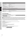
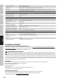
Gain Mic: -Inf to 45dB (SPK) / 38 dB (AUX Out)
Line: -Inf to 22dB (SPK) / 0 dB (AUX Out)
Phantom Power +24V, 10mA Switchable
VOX Threshold Mic: 0%: Off, 25%: -36 dBu, 50%: -48 dBu, 100%: -66 dBu
Line: 0%: Off, 25%: 1 dBu, 50%: -11 dBu, 100%: -28 dBu
Priority Contact closure +5VDC Normally Open for dry contact
Connector Mic/Line1: 5-pin Terminal Block, pitch 5.08mm + 1 XLR/6.3mm Jack combo connector
Mic/Line2: 3-pin Terminal Block, pitch 5.08mm + 1 dual RCA Mono Summed
Standby wake up threshold Mic: -70 dBu
Line: -35 dBu (Line), -40 dBu (Mono Sum)
Chime
Play time 2s
Resolution 12 Bit
Music inputs – CD/AUX
Nominal input sensitivity -6 dBV (Sine 1 kHz, Gain max)
Nominal input clipping 8 dBV (Sine 1kHz)
Connector 2 x dual RCA Mono Summed
THD+N < 0.05% (SPK OUT, -6 dBu, 20-20 kHz, CH Gain max, Master Gain max (0 dB), 20 kHz BW)
< 0.01% (AUX OUT, -6 dBu, 20-20 kHz, CH Gain max, 20 kHz BW)
Frequency response 20 Hz – 20 kHz (SPK OUT, -3 dB)
20 Hz – 20 kHz (AUX OUT, -3 dB)
Input Impedance 20 kohms (Unbalanced)
SNR >86 dB (SPK OUT, -4 dBu, CH Gain max (0 dB), Master Gain max (0 dB), 20 kHz BW, a-weighted)
>90 dB (AUX OUT, -6 dBu, CH Gain max (0 dB), 20 kHz BW, a-weighted)
SNR (Best conditions) >90 dB (SPX OUT, +10 dBu, CH Gain max (0 dB), Master Gain (-16 dB), 20 kHz BW, a-weighted)
>104 dB (AUX OUT, +10 dBu, Gain max (0 dB), 20 kHz BW, a-weighted)
Gain -Inf to 5 dB (AUX), 27dB (SPK)
Standby wake up threshold -45 dBu
Music input – BT
THD+N < 0.2% (SPK OUT, -10 dBFs, 20-20 kHz, Gain max, 20 kHz BW)
< 0.2% (AUX OUT, -10 dBFs, 20-20 kHz, Gain max, 20 kHz BW)
Frequency response 25 Hz – 20 kHz (SPK OUT, -3 dB)
25 Hz – 20 kHz (AUX OUT, -3 dB)
SNR >80 dB (SPK OUT, -10 dBFs, Gain max (0 dB), 20 kHz BW, a-weighted)
>80 dB (AUX OUT, -10 dBFs, Gain max (0 dB), 20 kHz BW, a-weighted)
SNR (Best conditions) >86 dB (SPX OUT, 0 dBFs, CH Gain max (0 dB), Master Gain (-10 dB), 20 kHz BW, a-weighted)
>93 dB (AUX OUT, 0 dBFs, Gain max (0 dB), 20 kHz BW, a-weighted)
Amplier Output
Type Class D
Amplier Outputs Low-Z: 4 ohm minimum load, High-Z 70V or 100V outputs
Connector 5-pin Terminal block (pitch 5.08mm)
RMS output power 35 W (Continuous sine wave 1kHz, 4 ohm load)
Peak output power 39 W (100 msec sine 1kHz Burst @ 4 ohm load)
Frequency response 20 Hz – 20 kHz (LO-Z, -3 dB)
60 Hz – 20 kHz (HI-Z, -3 dB)
Tone Control BASS: +-10dB (100Hz), TREBLE: +-10dB (10 kHz)
Protection Audio Limiter (10dB range), Over/Undervoltage, Overtemperature, Short-Circuit, Offset-Detection
Aux Output
Connector 3-pin Terminal block (pitch 5.08mm)
Frequency response 20 Hz – 20 kHz (-3 dB)
Maximum output level 22 dBu

16
ITALIANO
POLSKI
ESPAÑOL
FRANCAIS
DEUTSCHENGLISH
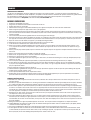
Power Supply
Type SMPS
Voltage Range 100 VAC – 240 VAC (+-10%), 50–60 Hz
Mains fuse T1.25A 250V
Connector IEC Jack
Safety Class Class 1
Max power consumption 70 W (sine 1kHz with 4 ohm load)
Idle power consumption 7 W (no signal input)
Standby power consuption < 1W
Operating Temperature 0°C – 40°C; < 85% humidity, non condensing
General
Time to standby 20 Min
Material Steel chassis, Plastic Front panel
Dimensions (W x H x D) 210 x 96.5 x 266.76 mm (height with rubber feet)
Weight 2.39 kg
Optional Accessories Rack mounting hardware
MANUFACTURER´S DECLARATIONS
MANUFACTURER‘S WARRANTY & LIMITATIONS OF LIABILITY
You can find our current warranty conditions and limitations of liability at: https://cdn-shop.adamhall.com/media/pdf/MANUFACTURERS-DECLARATIONS_
LD_SYSTEMS.pdf To request warranty service for a product, please contact Adam Hall GmbH, Adam-Hall-Str. 1,
61267 Neu Anspach / Email: [email protected] / +49 (0)6081 / 9419-0.
CORRECT DISPOSAL OF THIS PRODUCT
(valid in the European Union and other European countries with a differentiated waste collection system)
This symbol on the product, or on its documents indicates that the device may not be treated as household waste. This is to avoid environ-
mental damage or personal injury due to uncontrolled waste disposal. Please dispose of this product separately from other waste and have it
recycled to promote sustainable economic activity. Household users should contact either the retailer where they purchased this product, or their
local government office, for details on where and how they can recycle this item in an environmentally friendly manner. Business users should
contact their supplier and check the terms and conditions of the purchase contract. This product should not be mixed with other commercial waste
for disposal.
FCC STATEMENT
This device complies with Part 15 of the FCC Rules. Operation is subject to the following two conditions:
(1) This device may not cause harmful interference, and
(2) This device must accept any interference received, including interference that may cause undesired operation
CE COMPLIANCE
Adam Hall GmbH states that this product meets the following guidelines (where applicable):
R&TTE (1999/5/EC) or RED (2014/53/EU) from June 2017
Low voltage directive (2014/35/EU)
EMV directive (2014/30/EU)
RoHS (2011/65/EU)
The complete declaration of conformity can be found at www.adamhall.com.
Furthermore, you may also direct your enquiry to [email protected].
EU DECLARATION OF CONFORMITY
Hereby, Adam Hall GmbH declares that this radio equipment type is in compliance with Directive 2014/53/EU.
The full text of the EU declaration of conformity is available at the following
internet address: www.adamhall.com/compliance/

17
DEUTSCHFRANCAIS
ESPAÑOL ENGLISH
ITALIANO POLSKI
DEUTSCH
SIE HABEN DIE RICHTIGE WAHL GETROFFEN!
Dieses Gerät wurde unter hohen Qualitätsanforderungen entwickelt und gefertigt, um viele Jahre einen reibungslosen Betrieb zu gewährleisten.
Dafür steht LD Systems mit seinem Namen und der langjährigen Erfahrung als Hersteller hochwertiger Audioprodukte. Bitte lesen Sie diese
Bedienungsanleitung sorgfältig, damit Sie Ihr neues Produkt von LD Systems schnell optimal einsetzen können.
Mehr Informationen zu LD SYSTEMS finden Sie auf unserer Internetseite WWW.LD-SYSTEMS.COM
SICHERHEITSHINWEISE
1. Lesen Sie diese Anleitung bitte sorgfältig durch.
2. Bewahren Sie alle Informationen und Anleitungen an einem sicheren Ort auf.
3. Befolgen Sie die Anweisungen.
4. Beachten Sie alle Warnhinweise. Entfernen Sie keine Sicherheitshinweise oder andere Informationen vom Gerät.
5. Verwenden Sie das Gerät nur in der vorgesehenen Art und Weise.
6. Verwenden Sie ausschließlich stabile und passende Stative bzw. Befestigungen (bei Festinstallationen).
Stellen Sie sicher, dass Wandhalterungen
ordnungsgemäß installiert und gesichert sind. Stellen Sie sicher, dass das Gerät sicher installiert ist und nicht herunterfallen kann.
7. Beachten Sie bei der Installation die für Ihr Land geltenden Sicherheitsvorschriften.
8. Installieren und betreiben Sie das Gerät nicht in der Nähe von Heizkörpern, Wärmespeichern, Öfen oder sonstigen Wärmequellen.
Sorgen Sie dafür, dass das Gerät immer so installiert ist, dass es ausreichend gekühlt wird und nicht überhitzen kann.
9. Platzieren Sie keine Zündquellen wie z.B. brennende Kerzen auf dem Gerät.
10. Lüftungsschlitze dürfen nicht blockiert werden.
11. Halten Sie einen Mindestabstand von 20 cm seitlich und oberhalb des Geräts ein.
12. Betreiben Sie das Gerät nicht in unmittelbarer Nähe von Wasser. Bringen Sie das Gerät nicht mit brennbaren Materialien, Flüssigkeiten oder
Gasen in Berührung. Direkte Sonneneinstrahlung vermeiden!
13. Sorgen Sie dafür, dass kein Tropf- oder Spritzwasser in das Gerät eindringen kann. Stellen Sie keine mit Flüssigkeit gefüllten Behältnisse wie
Vasen oder Trinkgefäße auf das Gerät.
14. Sorgen Sie dafür, dass keine Gegenstände in das Gerät fallen können.
15. Betreiben Sie das Gerät nur mit dem vom Hersteller empfohlenen und vorgesehenen Zubehör.
16. Öffnen Sie das Gerät nicht und verändern Sie es nicht.
17. Überprüfen Sie nach dem Anschluss des Geräts alle Kabelwege, um Schäden oder Unfälle, z. B. durch Stolperfallen zu vermeiden.
18. Achten Sie beim Transport darauf, dass das Gerät nicht herunterfallen und dabei möglicherweise Sach- und Personenschäden verursachen kann.
19. Wenn Ihr Gerät nicht mehr ordnungsgemäß funktioniert, Flüssigkeiten oder Gegenstände in das Geräteinnere gelangt sind, oder das Gerät
anderweitig beschädigt wurde, schalten Sie es sofort aus und trennen es von der Netzsteckdose (sofern es sich um ein aktives Gerät handelt).
Dieses Gerät darf nur von autorisiertem Fachpersonal repariert werden.
20. Verwenden Sie zur Reinigung des Geräts ein trockenes Tuch.
21. Beachten Sie alle in Ihrem Land geltenden Entsorgungsgesetze. Trennen Sie bei der Entsorgung der Verpackung bitte Kunststoff und Papier bzw.
Kartonagen voneinander.
22. Kunststoffbeutel müssen außer Reichweite von Kindern aufbewahrt werden.
23. Sämtliche vom Benutzer vorgenommenen Änderungen und Modifikationen, denen die für die Einhaltung der Richtlinien verantwortliche Partei
nicht ausdrücklich zugestimmt hat, können zum Entzug der Betriebserlaubnis für das Gerät führen.
BEI GERÄTEN MIT NETZANSCHLUSS
24. ACHTUNG: Wenn das Netzkabel des Geräts mit einem Schutzkontakt ausgestattet ist, muss es an einer Steckdose mit Schutzleiter angeschlossen
werden. Deaktivieren Sie niemals den Schutzleiter eines Netzkabels.
25. Schalten Sie das Gerät nicht sofort ein, wenn es starken Temperaturschwankungen ausgesetzt war (beispielsweise nach dem Transport).
Feuchtigkeit und Kondensat könnten das Gerät beschädigen. Schalten Sie das Gerät erst ein, wenn es Zimmertemperatur erreicht hat.
26. Bevor Sie das Gerät an die Steckdose anschließen, prüfen Sie zuerst, ob die Spannung und die Frequenz des Stromnetzes mit den auf dem Gerät
angegebenen Werten übereinstimmen. Verfügt das Gerät über einen Spannungswahlschalter, schließen Sie das Gerät nur an die Steckdose an,
wenn die Gerätewerte mit den Werten des Stromnetzes übereinstimmen. Wenn das mitgelieferte Netzkabel bzw. der mitgelieferte Netzadapter
nicht in Ihre Netzsteckdose passt, wenden Sie sich an Ihren Elektriker.
27. Treten Sie nicht auf das Netzkabel. Sorgen Sie dafür, dass spannungsführende Kabel speziell an der Netzbuchse bzw. am Netzadapter und der
Gerätebuchse nicht geknickt werden.
28. Achten Sie bei der Verkabelung des Geräts immer darauf, dass das Netzkabel bzw. der Netzadapter stets frei zugänglich ist. Trennen Sie das Gerät
stets von der Stromzuführung, wenn das Gerät nicht benutzt wird, oder Sie das Gerät reinigen möchten. Ziehen Sie Netzkabel und Netzadapter
immer am Stecker bzw. am Adapter und nicht am Kabel aus der Steckdose. Berühren Sie Netzkabel und Netzadapter niemals mit nassen Händen.
29. Schalten Sie das Gerät möglichst nicht schnell hintereinander ein und aus, da sonst die Lebensdauer des Geräts beeinträchtigt werden könnte.
30. WICHTIGER HINWEIS: Ersetzen Sie Sicherungen ausschließlich durch Sicherungen des gleichen Typs und Wertes. Sollte eine Sicherung wiederholt
auslösen, wenden Sie sich bitte an ein autorisiertes Servicezentrum.
31. Um das Gerät vollständig vom Stromnetz zu trennen, entfernen Sie das Netzkabel bzw. den Netzadapter aus der Steckdose.
32. Wenn Ihr Gerät mit einem verriegelbaren Netzanschluss bestückt ist, muss der passende Gerätestecker entsperrt werden, bevor er entfernt
werden kann. Das bedeutet aber auch, dass das Gerät durch ein Ziehen am Netzkabel verrutschen und herunterfallen kann, wodurch Personen
verletzt werden und/oder andere Schäden auftreten können. Verlegen Sie Ihre Kabel daher immer sorgfältig.
33. Entfernen Sie Netzkabel und Netzadapter aus der Steckdose bei Gefahr eines Blitzschlags oder wenn Sie das Gerät länger nicht verwenden.
34. Das Gerät darf nicht von Personen (einschließlich Kindern) mit eingeschränkten körperlichen, sensorischen oder geistigen Fähigkeiten oder
mangelnder Erfahrung und Kenntnis benutzt werden.
35. Kinder müssen angewiesen werden, nicht mit dem Gerät zu spielen.

18
ITALIANO
POLSKI
ESPAÑOL
FRANCAIS
DEUTSCHENGLISH
36. Wenn das Netzkabel des Geräts beschädigt ist, darf das Gerät nicht verwendet werden. Das Netzkabel muss durch ein adäquates Kabel oder eine
spezielle Baugruppe von einem autorisierten Service-Center ersetzt werden.
ACHTUNG
Entfernen Sie niemals die Abdeckung, da sonst das Risiko eines elektrischen Schlages besteht. Im In-
neren des Geräts befinden sich keine Teile, die vom Bediener repariert oder gewartet werden können.
Lassen Sie Wartung und Reparaturen ausschließlich von qualifiziertem Servicepersonal durchführen.
Das gleichseitige Dreieck mit Blitzsymbol warnt vor nichtisolierten, gefährlichen Spannungen im Geräteinneren, die einen elektri-
schen Schlag verursachen können.
Das gleichseitige Dreieck mit Ausrufungszeichen kennzeichnet wichtige Bedienungs- und Wartungshinweise.
Warnung! Dieses Symbol kennzeichnet heiße Oberflächen. Während des Betriebs können bestimmte Teile des Gehäuses heiß wer-
den. Berühren oder transportieren Sie das Gerät nach einem Einsatz erst nach einer Abkühlzeit von mindestens 10 Minuten.
Warnung! Dieses Gerät ist für eine Nutzung bis zu einer Höhe von maximal 2000 Metern über dem Meeresspiegel bestimmt.
Warnung! Dieses Gerät ist nicht für den Einsatz in tropischen Klimazonen bestimmt.
ACHTUNG HOHE LAUTSTÄRKEN BEI AUDIOPRODUKTEN!
Dieses Gerät ist für den professionellen Einsatz vorgesehen. Der kommerzielle Betrieb dieses Geräts unterliegt den jeweils gültigen nationalen Vor-
schriften und Richtlinien zur Unfallverhütung. Als Hersteller ist Adam Hall gesetzlich verpflichtet, Sie ausdrücklich auf mögliche Gesundheitsrisiken
hinzuweisen. Gehörschäden durch hohe Lautstärken und Dauerbelastung: Bei der Verwendung dieses Produkts können hohe Schalldruckpegel (SPL)
erzeugt werden, die bei Künstlern, Mitarbeitern und Zuschauern zu irreparablen Gehörschäden führen können. Vermeiden Sie länger anhaltende
Belastung durch hohe Lautstärken über 90 dB.

19
DEUTSCHFRANCAIS
ESPAÑOL ENGLISH
ITALIANO POLSKI
EINLEITUNG
Bei Festinstallationen stehen neben einer unauffälligen Optik besonders die Flexibilität und Vielseitigkeit des Mischverstärkers im Vordergrund.
Verschiedene Signalquellen und Mikrofone müssen angeschlossen werden können. Bei Notfällen müssen die Eingangssignale einfach stummzu-
schalten sein, um Durchsagen oder Notrufe zu ermöglichen. Mit dem IMA 30 präsentiert LD Systems den ersten Vertreter der neuen Mischverstärker
aus der IMA-Serie, der hinsichtlich Design und Flexibilität keine Wünsche offen lässt.
Sein kompaktes Design im 9,5-Zoll-Gehäuse, vielfältige Anschlussmöglichkeiten inklusive Bluetooth für den drahtlosen Anschluss von Musikquellen
sowie eine mehrstufige Prioritätsschaltung garantieren die nahtlose Integration in kommerzielle und industrielle Anwendungen. Der IMA 30 bietet
vier Prioritäts-Ebenen für Notrufe und Mikrofon- / Line-Eingänge für verschiedene Signal- und Musikquellen. Wahlweise kann auch ein automati-
scher Standby-Modus aktiviert werden, um den Stromverbrauch weiter zu reduzieren.
Der Mischverstärker verfügt über zwei Prioritäts-Kontaktschlüsse: einen für den Notfall-Eingang, der alle anderen Signalquellen des Geräts stumm-
schaltet, und einen für die Mikrofoneingänge, der die Musik-Signalquellen stummschaltet. Die Ausgänge bieten eine Leistung von 30 W bei 4 Ohm,
einen 2-Band-EQ für Bässe und Höhen sowie einen 70 V / 100 V-Abgriff. Mithilfe des High-Z / Low-Z Wahlschalters kann das Ausgangssignal vollständig
vom Ausgangstransformator getrennt werden, was einen optimalen Frequenzgang bei Anwendungen mit niedriger Eingangsimpedanz gewährleistet.
Externe Endstufen, aktive Subwoofer oder Systeme für Warteschleifenmusik lassen sich über den integrierten Aux-Ausgang mit dem IMA 30 kombinie-
ren. Mit dem Music-Mix-Wahlschalter entscheiden Sie außerdem, ob der gesamte Mix oder nur die gewählte Musik-Signalquelle an den Aux-Ausgang
übertragen werden soll. Das intuitive Design des Bedienfelds mit kapazitiven Tastern für die Auswahl der Musik-Signalquelle, die übersichtliche der
Rückplatte und das kompakte 9,5-Zoll-Format sorgen dafür, dass bei der Installation des Mischverstärkers keine Probleme auftreten.
FEATURES
• Line-Eingang für Notfallsignal mit Schließerkontakt
• 2 Mic/Line-Eingangs-Klemmleisten mit Mikrofon/Line-Umschaltung und zuschaltbarer 24-V-Phantomspeisung
• Zuschaltbare Gong-Funktion für Mic/Line-Kanal 1
• 2 Line-Eingänge mit Cinch-Buchsen plus Bluetooth 4.0-Schnittstelle (Monosumme)
• Class-D-Verstärker mit 30 W Leistung
• Ausgang für niederohmige Lautsprecher und 70/100-V-Ausgänge mit LO-Z/HI-Z-Umschaltung. Im niederohmigen Betrieb ist das Audiosignal für
einen optimalen Frequenzgang vollständig von den Transformatoren getrennt.
• Symmetrischer AUX-Line-Ausgang für die Ansteuerung externer Geräte (Verstärker, aktive Subwoofer, Systeme für Warteschleifenmusik)
• Music-Mix-Taste zur Auswahl des via AUX-Ausgang ausgegebenen Signals (Gesamtmischung oder gewählte Musik-Zuspielquelle)
• Separate Klangregelung für Höhen und Bässe auf der Geräterückseite
• 4 Priority-Einstellungen für vielfältige Integrationsmöglichkeiten
• Zuschaltbarer Auto-Standby-Modus zur Energieeinsparung
• Benutzerfreundliche Bedienoberfläche – intuitive Bedienung über kapazitive Controller (Auswahl der Musik-Zuspielquelle und Bluetooth-Pairing)
• Einfache Installation dank übersichtlich angeordneter und beschrifteter Anschlüsse und Bedienelemente auf der Rückseite
• Universelles Weitbereichs-Schaltnetzteil
• Format: Halbe Rack-Breite, 2 HE
• Optional: Rack-Montagekit (IMA RK) zur Installation von ein oder zwei IMA 30/60-Einheiten in einem 19"-Rack
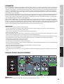
ANSCHLÜSSE, BEDIENUNG UND ANZEIGEELEMENTE
2
1
3XLR f
1
3
2
XLR m
2
6
3
9
10
578 4
1
1 NETZBUCHSE
IEC-Kaltgerätebuchse zur Stromversorgung des Geräts (Netzkabel im Lieferumfang).

20
ITALIANO
POLSKI
ESPAÑOL
FRANCAIS
DEUTSCHENGLISH
2 SICHERUNG
Sicherungshalter für 250-V-Mikrosicherungen (5 x 20 mm). WICHTIGER HINWEIS: Ersetzen Sie die Sicherung ausschließlich durch eine Sicherung
gleichen Typs (siehe aufgedruckte Hinweise auf dem Gehäuse). Sollte die Sicherung mehrfach auslösen, wenden Sie sich bitte an ein autorisiertes
Service-Center.
3 ON/OFF
Wippschalter zum Ein- und Ausschalten des Geräts.
4 EMERGENCY
5-Pol-Klemmleiste zur Installation eines akustischen Notrufsystems. Die Pole +, - und G entsprechen einem symmetrischen Line-Eingang. Die Pole C
und + dienen dem Anschluss eines separaten Mute-Schalters (Klemmleiste im Lieferumfang). Die VOX-Steuerung (Voice Operated Exchange) bietet
die Möglichkeit, einen Schwellwert für das Notfall-Audiosignal festzulegen, um so einen automatischen Mute-Schaltkreis zu aktivieren. Wenn der
Pegel am EMERGENCY-Eingang den eingestellten Schwellwert erreicht, werden alle anderen Mikrofon- und Line-Kanäle stummgeschaltet. So ist
sichergestellt, dass das Notfallsignal klar und deutlich zu hören ist. Außerdem leuchtet in diesem Fall die Anzeige EMERG vorne am Verstärker. Sobald
der Pegel des Notfallsignals unter den eingestellten Schwellwert fällt, wird die Stummschaltung der anderen Kanäle wieder aufgehoben und die
EMERG-Anzeige erlischt. Bei entsprechender Einstellung hat der EMERGENCY-Kanal immer höchste Priorität. Das Notfallsignal wird intern direkt an die
Endstufe und den Lautsprecherausgang überführt. Der Pegel des Notfallsignals wird nicht von der aktuellen Einstellung des Haupt-Lautstärkereglers
(Master Volume) beeinusst, sondern über den GAIN-Regler eingestellt. Über den Schließerkontakt für den EMERGENCY-Kanal (Pole C und +) werden
alle anderen Eingangskanäle stummgeschaltet, unabhängig von der VOX-Einstellung. Steht der VOX-Regler auf Minimum (ganz nach links gedreht), ist
die automatische Stummschaltung via VOX-Schaltkreis deaktiviert, und der EMERGENCY-Kanal kann als zusätzlicher Line-Kanal genutzt werden.
5 MIC/LINE 1
Mikrofon/Line-Kanal mit zuschaltbarer Gong-Funktion (Signalton). Der Anschluss kann sowohl über die XLR/Klinke-Kombibuchse als auch per
Klemmleiste erfolgen. In diesem Fall sind die Pole +, - und G an der Klemmleiste für das symmetrische Eingangssignal vorgesehen. Die Pole C
und + dienen dem Anschluss eines separaten Mute-Schalters (Klemmleiste im Lieferumfang). Wenn an der XLR/Klinke-Kombibuchse oder an der
Klemmleiste ein Line-Signal anliegt, schalten Sie den MIC/LINE-Kanal 1 über die zugehörige MIC/LINE-Taste in den LINE-Betrieb (Taste gedrückt). Ist
ein Mikrofon angeschlossen, aktivieren Sie über die MIC/LINE-Taste den MIC-Betrieb (Taste nicht gedrückt). Bei Verwendung eines Kondensatorm-
ikrofons ist es außerdem erforderlich, die 24-V-Phantomspeisung zu aktivieren (Taste PHANTOM ON/OFF gedrückt: ON). Vergewissern Sie sich stets,
dass das Mikrofon angeschlossen und die Kanallautstärke auf Minimum eingestellt ist, bevor Sie die Phantomspeisung einschalten. Bevor Sie das
Mikrofon wieder vom Verstärker trennen, deaktivieren Sie die Phantomspeisung und drehen die Kanallautstärke auf Minimum. Der Schließerkontakt
(Pole C und +) bietet die Möglichkeit, den MUSIC-Kanal über einen externen Schalter/Taster stummzuschalten. Außerdem kann auf diese Weise
die interne Gong/Signalton-Funktion angesteuert werden, wenn der Schaltkreis aktiviert ist. Die Lautstärke für den Gong/Signalton wird über den
CHIME-Regler auf der Rückseite des Verstärkers gesteuert. Wenn der Regler ganz nach links gedreht ist, ist der Gong/Signalton-Schaltkreis deak-
tiviert. Ist die interne Gong/Signalton-Funktion aktiv, werden die Kanäle MIC/LINE 1, MIC/LINE 2 und MUSIC für die Dauer des Signaltons stummges-
chaltet. Die VOX-Steuerung ermöglicht es, für MIC/LINE-Eingang 1 einen Audio-Schwellwert für einen automatischen Mute-Schaltkreis festzulegen,
so dass die Kanäle MIC/LINE 2 und MUSIC stummgeschaltet werden, sobald das Eingangssignal den vordenierten Pegel erreicht. Die VOX-Steuerung
ermöglicht es, für MIC/LINE-Eingang 1 einen Audio-Schwellwert für einen automatischen Mute-Schaltkreis festzulegen, so dass die Kanäle MIC/LINE 2
und MUSIC stummgeschaltet werden, sobald das Eingangssignal den vordenierten Pegel erreicht. Die PRIO-LED auf der Vorderseite leuchtet, wenn
Schließerkontakt oder VOX-Schaltkreis aktiv sind. Sobald der Eingangspegel des Notfallsignals unter den eingestellten Schwellwert fällt, wird die
Stummschaltung der Kanäle wieder aufgehoben und die PRIO-LED erlischt. Bei entsprechender Konguration hat MIC/LINE 1 Priorität über MIC/LINE 2
und MUSIC. Die Kanallautstärke stellen Sie über den Regler 1 auf der Vorderseite des Verstärkers ein.
6 MIC/LINE 2
Mikrofon/Line-Kanal. Der Anschluss kann sowohl über die Line-Cinch-Buchsen (Monosumme) als auch die Klemmleiste erfolgen. In diesem Fall
sind die Pole +, - und G an der Klemmleiste für das symmetrische Eingangssignal vorgesehen (Klemmleiste im Lieferumfang). Wenn an den Cinch-
Buchsen oder an der Klemmleiste ein Line-Signal anliegt, schalten Sie den MIC/LINE-Kanal 2 über die zugehörige MIC/LINE-Taste in den LINE-Betrieb
(Taste gedrückt). Ist ein Mikrofon an der Klemmleiste angeschlossen, aktivieren Sie über die MIC/LINE-Taste den MIC-Betrieb (Taste nicht gedrückt).
Bei Verwendung eines Kondensatormikrofons ist es außerdem erforderlich, die 24-V-Phantomspeisung zu aktivieren (Taste PHANTOM ON/OFF
gedrückt: ON). Vergewissern Sie sich stets, dass das Mikrofon angeschlossen und die Kanallautstärke auf Minimum eingestellt ist, bevor Sie die
Phantomspeisung einschalten. Bevor Sie das Mikrofon wieder vom Verstärker trennen, deaktivieren Sie die Phantomspeisung und drehen die
Kanallautstärke auf Minimum.
Tipp: Sie können die Kontakte (Pole C und +) für MIC/LINE 1 auch nutzen, um dem Kanal MIC/LINE 2 Priorität über den MUSIC-Kanal zu gewähren.
Außerdem können parallel zum Schließerkontakt externe Schalter/Taster für MIC/LINE 1 und MIC/LINE 2 eingesetzt werden.
7 MUSIC
Line-Kanal zur Einbindung von Zuspielquellen wie CD- oder MP3-Player. Der MUSIC-Kanal ist zusätzlich mit einem Bluetooth-Modul ausgestattet.
Rückseitig stehen Cinch-Buchsen für den Anschluss zweier Stereo-Line-Eingangssignalquellen zur Verfügung (CD-Symbol bzw. Kabel-Symbol). Die
Auswahl der gewünschten Signalquelle erfolgt über einen berührungsempndlichen Taster auf der Vorderseite des Verstärkers. Alle anliegenden
Stereosignale werden intern in ein Monosignal überführt.
8 AUX OUT
Der Line-Ausgang AUX OUT mit Klemmleisten-Anschluss dient der Signalausgabe zum Beispiel an einen externen Verstärker, einen aktiven Subwoof-
er oder ein System für Telefon-Warteschleifenmusik (Klemmleiste im Lieferumfang). Über die Taste MUSIC-MIX kann wahlweise nur das Signal des
Musik-Kanals (Position MUSIC) oder die Summe aller Kanäle (Position MIX) an den Ausgang überführt werden.
Bitte beachten Sie: In der Werkseinstellung ist das EMERGENCY-Signal (Notfallsignal) über einen internen Jumper auf den Line-Ausgang AUX OUT
geroutet. Soll diese Einstellung geändert werden, muss das Gerät geöffnet und der entsprechende Jumper entfernt werden. Bitte lesen Sie hierzu
die Informationen unter „JUMPER FÜR NOTFALLSIGNAL AN AUX OUT“ in dieser Bedienungsanleitung.
Strona się ładuje...
Strona się ładuje...
Strona się ładuje...
Strona się ładuje...
Strona się ładuje...
Strona się ładuje...
Strona się ładuje...
Strona się ładuje...
Strona się ładuje...
Strona się ładuje...
Strona się ładuje...
Strona się ładuje...
Strona się ładuje...
Strona się ładuje...
Strona się ładuje...
Strona się ładuje...
Strona się ładuje...
Strona się ładuje...
Strona się ładuje...
Strona się ładuje...
Strona się ładuje...
Strona się ładuje...
Strona się ładuje...
Strona się ładuje...
Strona się ładuje...
Strona się ładuje...
Strona się ładuje...
Strona się ładuje...
Strona się ładuje...
Strona się ładuje...
Strona się ładuje...
Strona się ładuje...
Strona się ładuje...
Strona się ładuje...
Strona się ładuje...
Strona się ładuje...
Strona się ładuje...
Strona się ładuje...
Strona się ładuje...
Strona się ładuje...
Strona się ładuje...
Strona się ładuje...
Strona się ładuje...
Strona się ładuje...
Strona się ładuje...
Strona się ładuje...
Strona się ładuje...
Strona się ładuje...
Strona się ładuje...
Strona się ładuje...
Strona się ładuje...
Strona się ładuje...
Strona się ładuje...
Strona się ładuje...
Strona się ładuje...
Strona się ładuje...
Strona się ładuje...
Strona się ładuje...
Strona się ładuje...
Strona się ładuje...
Strona się ładuje...
Strona się ładuje...
Strona się ładuje...
Strona się ładuje...
Strona się ładuje...
Strona się ładuje...
Strona się ładuje...
Strona się ładuje...
-
 1
1
-
 2
2
-
 3
3
-
 4
4
-
 5
5
-
 6
6
-
 7
7
-
 8
8
-
 9
9
-
 10
10
-
 11
11
-
 12
12
-
 13
13
-
 14
14
-
 15
15
-
 16
16
-
 17
17
-
 18
18
-
 19
19
-
 20
20
-
 21
21
-
 22
22
-
 23
23
-
 24
24
-
 25
25
-
 26
26
-
 27
27
-
 28
28
-
 29
29
-
 30
30
-
 31
31
-
 32
32
-
 33
33
-
 34
34
-
 35
35
-
 36
36
-
 37
37
-
 38
38
-
 39
39
-
 40
40
-
 41
41
-
 42
42
-
 43
43
-
 44
44
-
 45
45
-
 46
46
-
 47
47
-
 48
48
-
 49
49
-
 50
50
-
 51
51
-
 52
52
-
 53
53
-
 54
54
-
 55
55
-
 56
56
-
 57
57
-
 58
58
-
 59
59
-
 60
60
-
 61
61
-
 62
62
-
 63
63
-
 64
64
-
 65
65
-
 66
66
-
 67
67
-
 68
68
-
 69
69
-
 70
70
-
 71
71
-
 72
72
-
 73
73
-
 74
74
-
 75
75
-
 76
76
-
 77
77
-
 78
78
-
 79
79
-
 80
80
-
 81
81
-
 82
82
-
 83
83
-
 84
84
-
 85
85
-
 86
86
-
 87
87
-
 88
88


LD systems LD IMA 30 Mixing Amplifier Instrukcja obsługi
- Typ
- Instrukcja obsługi
w innych językach
Inne dokumenty
-
LD Systems AMP 205 Instrukcja obsługi
-
-
-
Yamaha MV800 Instrukcja obsługi
-
-
-
Yamaha EMX5 Instrukcja obsługi
-
Yamaha EMX7 Instrukcja obsługi
-